Close
0%
0%

Universal battery

Universal stackable energy storage device capable of receiving and delivering power to the same common low voltage bus (12V).

Similar projects worth following
This projects is a solution to creating high capacity modular battery consisting of different cells. The matching circuits allows connecting cells of different capacity, voltage and age to one common low-voltage bus for storing and delivering energy. It gives second life for used cells which cannot be longer connected together into big series battery pack and creates possibility of creating reconfigurable network of energy storage.
The main element of the project is a cell matching circuit which dynamically raises single cell voltage to the predefined main bus level and decide on direction of energy transfer. The matching circuit makes cells in a single unit an “ideal” voltage source capable of sourcing and sinking current. This allows for different units to share single bus for energy output and consumption. The matching circuit is in essence a bi-directional dc-dc converter with an accompanied microcontroller which act as a converter controller and cell monitor.

Motivation

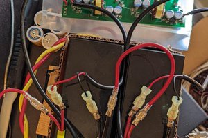
Being in the hacking business for some time now, I  have accumulated a box of different lithium batteries. Most of them partially used, they usually came from the battery packs in which only one cell from the pack shows signs of permanent death rendering others cells in series unusable. Having this box of usable cells I was considering different alternatives of connecting them into bigger battery to create some stationary energy storage for renewable energy sources.

Implementation

To use any battery efficiently two things are usually required; a dedicated charger and converter which will change battery floating voltage to suit final energy receiver. When bigger capacity batteries are required, the number of cells is increased and bigger charger and converter are fitted. This creates the problem of single point of failure when single cell in the battery fails.

This project aims to solve this problem by creating modular solution in which big capacity battery is created from number of small units which each contains its own charger, converter and battery monitor circuit. By using bi-directional topology, charger and output converter circuit can be implemented using the same power stage elements.

By using distributed approach to energy storage the whole system capacity does not have to be predefined and does not have to be reliant on every single part working. If the elements are design to gracefully fail the whole system can operate even with partial capacity.

Bi-directional converter

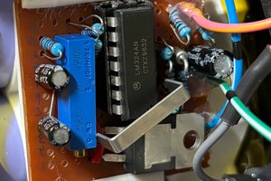
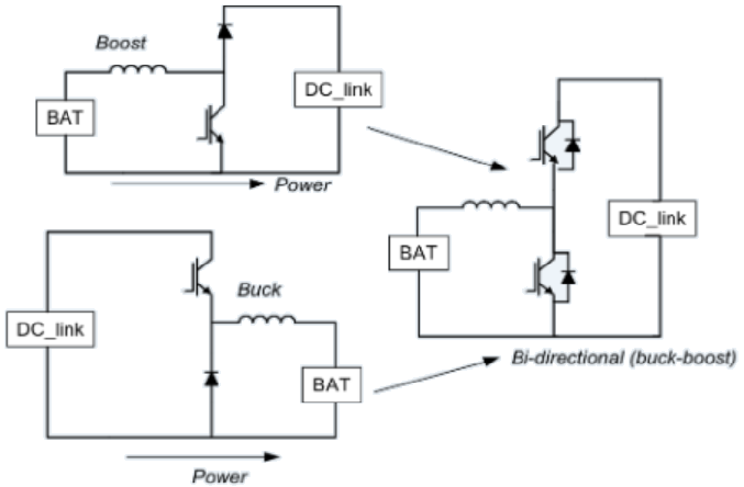
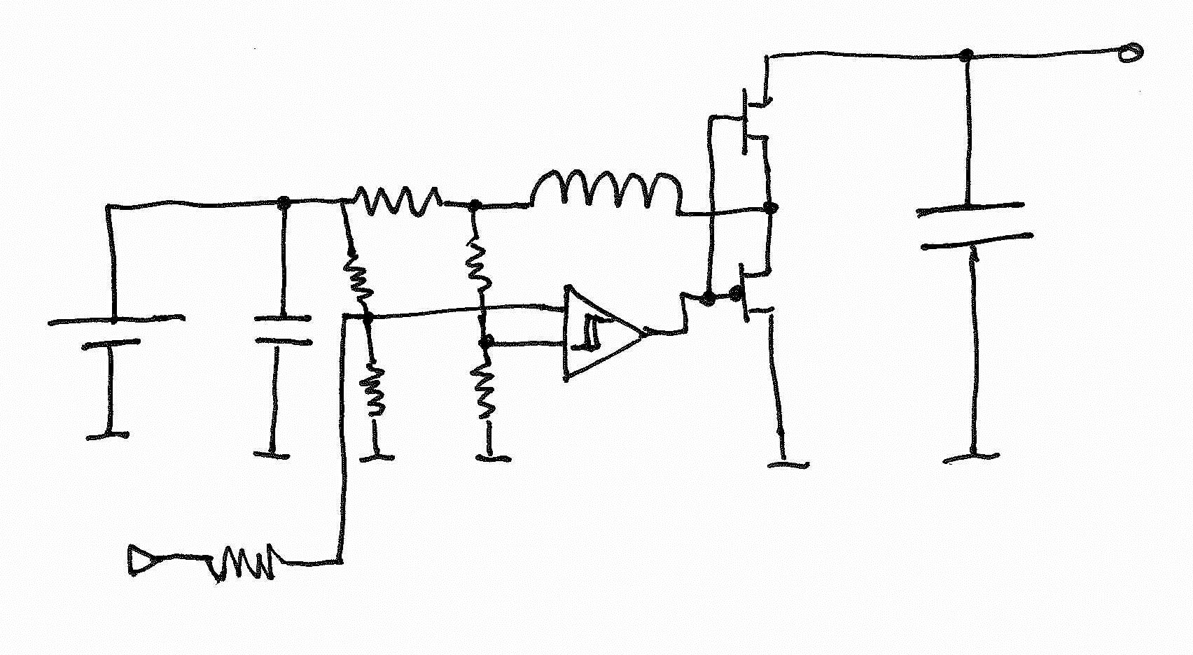
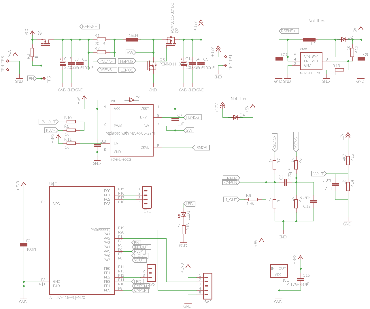
To be able to connect multiple of energy storage units together they all have to match in output voltage. That calls for switch mode converter. By using bi-directional converter the power elements can double up for charger and output converter (see figure below). There is a number of designed switch mode controllers IC but none (very few) of them support bidirectional energy transfer. That is why I was forced to create custom controller which was problematic but in the end it lower the parts count since the microcontroller was already required for battery monitoring.

Ideal constant voltage source

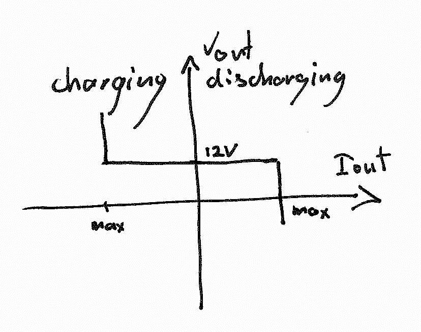
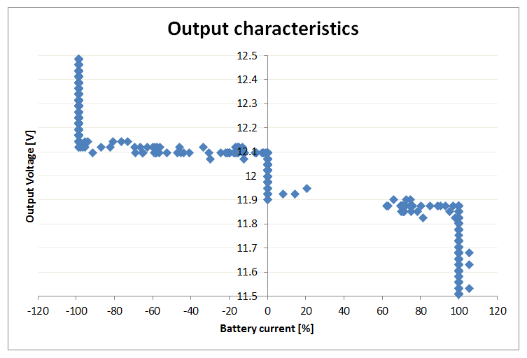
The ideal desired characteristics of the designed power converter is to make the energy storage cell an ideal voltage source. The unit should source or sink current to keep the constant voltage at the output. Of course there are safety limits to maximal output and input currents so the controller should switch to constant current source when those are crossed.

 Voltage controlled current source

There is a number of ways to create feedback loop for switch mode power converters, after considering alternatives and the available parts I decided to experiment with maximum inductor current limiting. I sketched an idea of using comparator with hysteresis to create unstable/oscilating bidirectional current limiting circuit which keeps the inductor current within predefined bounds. By injecting external offset it creates voltage controlled current source. See the figure bellow.

"Bang-bang" output voltage control

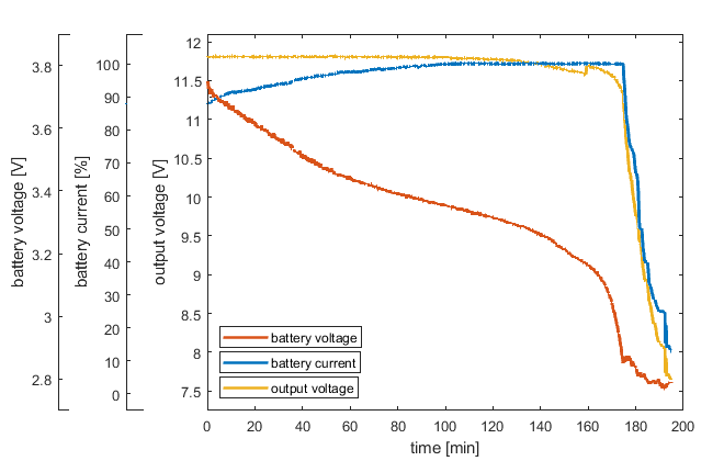
Having this concept of voltage controlled current source block I had to draw a rules for closing the feedback loop. I decided to go for simple and fast “bang-bang” controller to keep the output voltage and battery voltage within bounds. The controller in fast 50kHz loop executing simple code:

If((OutputVoltage<11.9V)&&(BatteryVoltage>2.8V)) //Output mode
                SourceMaximumCurrent();
Else if((OutputVoltage>12.1V)&&(BatteryVoltage<4.2V)) //Charging mode
                SinkMaximumCurrent();
Else
                KeepOutputCurrentZero();

schematic.zip

Schematic and PCB in Eagle 7.5.0 format and png.

Zip Archive - 709.67 kB - 05/30/2019 at 23:17

Download

code.zip

Code in Atmel Studio 7.0 project format.

Zip Archive - 45.68 kB - 05/30/2019 at 23:17

Download

  • Charging and discharging test

    Peter Bogdan05/30/2019 at 15:03 0 comments

    Here are the graphs of first charging and discharging runs. The battery was loaded with 500mA current sink during discharge and supplied from 13V  (1Alimit) voltage source during charging.

    During discharge the converter passes trough three modes. First is the constant output voltage. As the battery voltage drops, the battery current rises to the maximum limit. At that point the converter enters into maximum current regulation and the output voltage starts to fall. As the battery voltage reaches minimal value of 2.8V the maximum current starts to be lowered to avoid over discharge at that point the output voltage falls even lower and the test is stopped when the current falls below 10% of maximum value.


    During charging similar three modes of operation are visible. The first one is the short period of maximum battery current limit. Then as the battery require more charging power (battery voltage rises and current stays the same) the power supply input start to fall under the input voltage limit (12.1V) and the converter start to lower charging current not to over-load the source. As the battery starts to reach maximal voltage (4.2) the charging current starts to be lowered and the power supply can recover back to initial 13V.

  • First start-up

    Peter Bogdan05/30/2019 at 14:46 0 comments

    I connected the converter to 4 Li-ion 18650 cells and its output to load resistor parallel with regulated power supply. This way a could change the amount of load put to converter both sourcing and sinking current. To keep the microcontroller "independent" I powered it and mosfet driver from 5V USB-port through the rs-232 converter to which the microcontroller was reporting internal state. Bellow is the is the plot of self-reported output voltage vs battery current. The two modes of operation can be seen in which converter sinks current when the voltage is above 12.1V and sources current when voltage is bellow 11.9V. At certain level the converter goes into maximum current protection and the converter switches to constant (battery) current mode.


    The test setup:

  • Schematic and PCB

    Peter Bogdan05/30/2019 at 14:21 0 comments

    I come up with first schematic to test the idea. I went for cheap microcontroller with the fast ADC, DAC and Analogue Comparator (Attiny816). I considering other microcontrollers and possibly outside peripherals like faster ADC but I settle for peripherals build in into attiny for now. I experiment with Mosfet drivers on the beginning I tried NCP5901 because of tri-state input capability. Unfortunately build-in safety features for driving only buck converters kept shutting down the driver with internal fault. I switched to MIC4605-2YM which is simpler but requires higher supply voltage. The rest of the schematic is simple and some of the components are not even fitted for the test PCB. See the schematic and board design bellow.

View all 3 project logs

Enjoy this project?

Share

Discussions

Similar Projects

Does this project spark your interest?

Become a member to follow this project and never miss any updates