 kodera2t
Regenerative and super-regenerative receiver are well-known circuits to build "simple but high sensitivity radio". These two words are similar but different in the principle. "regenerative" is simply build by "full positive feedback loop" to get high gain, and very easy to oscillate for strong signal input. (feedback value should be adjusted for each reception.) Indeed, it was super popular just after WWII in Japan, but GHQ prohibited to sell due to too much spurious emission in EM environment (I guess it jammed communication..)
Super-regenerative is periodically oscillating oscillator, which pulse width is modulated by input signal. Indeed, it can work not only low frequency but up to GHz range, including second harmonics (very close to injection locking) but it has a issue of noise emission.
The circuit of "reflex" is different from regenerative nor super-regenerative.
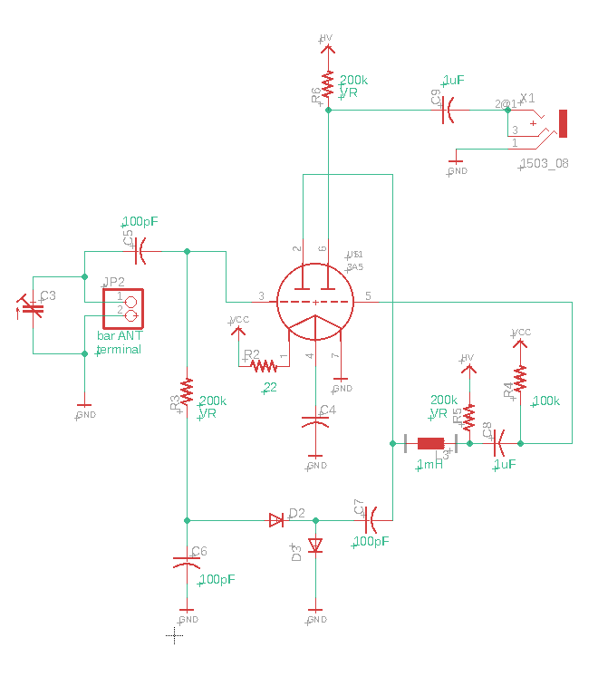
Here is one example circuit can be made in breadboard. You may find similarity with #1 straight radio, but sooner you will find one strange point. D2, and D3 consisting rectifier, but the output goes back to the grid (#3)??
This is the way to operate. C3, and ferrite bar antenna in JP2 consists resonator, and goes to one of twin triode, grid (#3). The amplified RF signal goes to C7 and entering D2 and D3 and they produce audio signal. The shunt capacitor and R3 will work as LPF and the audio signal goes gain to #3. YES, it is feedback look. The difference between regenerative and reflex are, regenerative will feedback everything including RF and AF, but in the case of reflex, only AF signal has a feedback look (therefore, no fear of RF signal oscillation and emission.) Again the amplified AF (and RF) signal goes to grid #3 and amplified again and goes to L3. L3 is RFC and only AF signal goes through, and the filtered AF signal goes to second grid (#5) and amplified and goes out to earphone terminal. Yeah, it works as like this.
Indeed, I've completed the preparation as kit form and started to sell at my tindie store. But of course you can find parts by yourself and easily make this radio circuit. Compared with #1 radio, reflex has more good sensitivity and if you can find proper impedance transformer, you may be able to drive speaker just by single tube! Please try!
Discussions
Become a Hackaday.io Member
Create an account to leave a comment. Already have an account? Log In.