 kodera2t
Vacuum tube was made till around mid-80's even in US. Mostly they are military application and no consumer product except for high-end audio did use tube in that era. This time I got a vacuum tube made in such the end of vacuum tube era. It is "subminiature tube". Quickly I wired the radio (single tube reflex) #3 and show how it works in the following movie. The schematic and parameter will be presented later on this page but I can show now its operation.
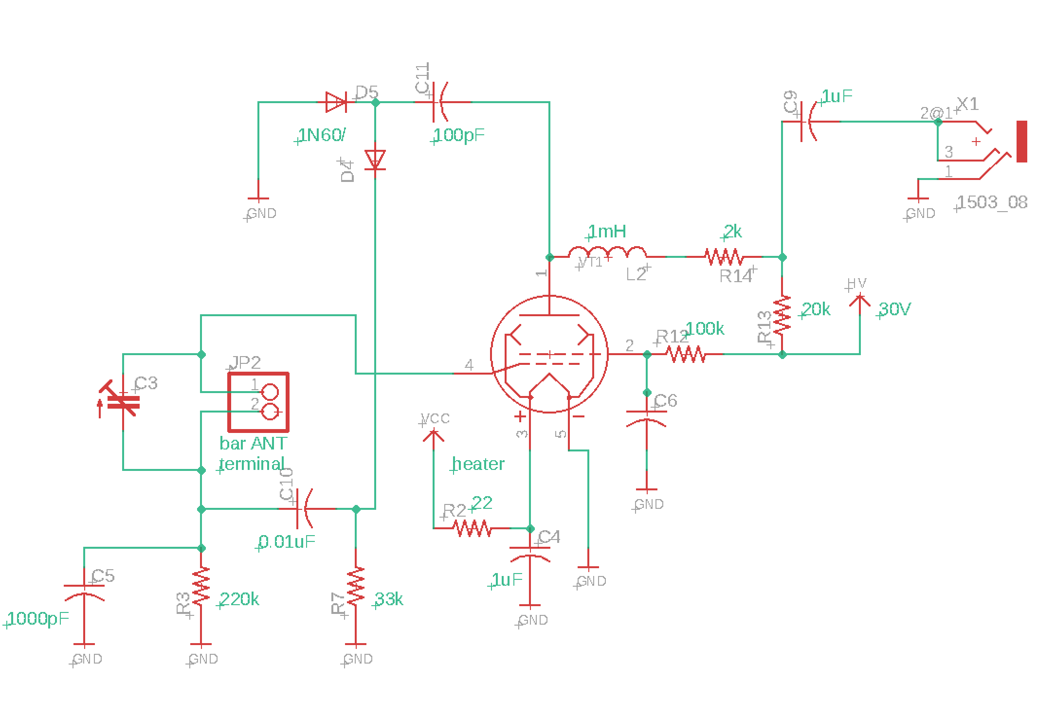
And this is the schematic. It is quite simple but relatively high sensitive. Here let's follow the signal from RF to AF. Initially ferrite bar antenna and C3 (variable capacitor) organizing resonator and tuned signal goes to grid 1 (#4), and amplified signal from plate (#1pin) will deliver signal to diode rectifier (initially it does not contain AF and L2 works as RF choke) and rectified RF signal turns to audio signal and again go to resonator (C3 and ferrite bar) and again goes grid 1(#4). The amplified AF and RF comes out from #1pin (plate) and now audio signal can go through RF choke and indeed again some of them go to grid 2 (#2pin) and amplified audio signal comes out from plate #1pin. Indeed, it has a two loop for grid1 and grid 2, and both of them are audio signal feedback loop. (not RF). So RF oscillation will not occur (but audio oscillation can, indeed).Most of pentode can be replaced with small modification for heater voltage and R13 and R7.
Discussions
Become a Hackaday.io Member
Create an account to leave a comment. Already have an account? Log In.