 agp.cooper
Using Divide and Conquer
Instead of a single hard coded procedure, use some intelligent sub-routines (i.e. procedures).
What am I talking about? My BoxMaker code terrible. It is 800 lines long, hard coded and took forever to write and test.
Intelligent code would be code that progressively breaks the problem down into sub-problems. Sub-problems are always easy to code and debug.
Okay, here is the new and very short "makeBox" procedure (not yet fully featured but a start):
static void makeBox(FILE *F1,char *LayerName,int LayerColour,double Length,double Width,double Height,double XOffset,double YOffset,bool Direction,double Tab,double Flange)
{
  makeSquare(F1,LayerName,LayerColour,XOffset               ,YOffset         , Width,Length,Direction,-Tab,-Tab,Flange); // Top  #1 - Slot/Slot
  makeSquare(F1,LayerName,LayerColour,3*XOffset+Width       ,YOffset         ,Height,Length,Direction, Tab,-Tab,   0.0); // Side #1 - Slot/Tab
  makeSquare(F1,LayerName,LayerColour,5*XOffset+Width+Height,YOffset         ,Height, Width,Direction, Tab, Tab,   0.0); // End  #1 - Tab/Tab
  makeSquare(F1,LayerName,LayerColour,XOffset               ,YOffset*3+Length, Width,Length,Direction,-Tab,-Tab,Flange); // Top  #2 - Slot/Slot
  makeSquare(F1,LayerName,LayerColour,3*XOffset+Width       ,YOffset*3+Length,Height,Length,Direction, Tab,-Tab,   0.0); // Side #2 - Slot/Tab
  makeSquare(F1,LayerName,LayerColour,5*XOffset+Width+Height,YOffset*3+Length,Height, Width,Direction, Tab, Tab,   0.0); // End  #2 - Tab/Tab
}
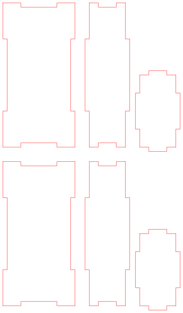
So what does it do? It creates six squares that represent the sides of the box, like this:

But to create those squares it has to call a "makeSquare" procedure:
static void makeSquare(FILE *F1,char *LayerName,int LayerColour,double XStart,double YStart,double Width,double Height,bool Direction,double TabX,double TabY,double Flange)
{
  DXF_PolylineBegin(F1,LayerName,LayerColour);
  if (Direction) { // Clockwise
    makeLine(F1,LayerColour,XStart      ,YStart       ,XStart      ,YStart+Height,Direction,TabX,Flange);
    makeLine(F1,LayerColour,XStart      ,YStart+Height,XStart+Width,YStart+Height,Direction,TabY,Flange);
    makeLine(F1,LayerColour,XStart+Width,YStart+Height,XStart+Width,YStart       ,Direction,TabX,Flange);
    makeLine(F1,LayerColour,XStart+Width,YStart       ,XStart      ,YStart       ,Direction,TabY,Flange);
  } else {         // Anti-clockwise
    makeLine(F1,LayerColour,XStart      ,YStart       ,XStart+Width,YStart       ,Direction,TabY,Flange);
    makeLine(F1,LayerColour,XStart+Width,YStart       ,XStart+Width,YStart+Height,Direction,TabX,Flange);
    makeLine(F1,LayerColour,XStart+Width,YStart+Height,XStart      ,YStart+Height,Direction,TabY,Flange);
    makeLine(F1,LayerColour,XStart      ,YStart+Height,XStart      ,YStart       ,Direction,TabX,Flange);
  }
  DXF_PolylineEnd(F1);
}
And makeSquare calls makeLine, that makes lines with "tabs", like this:
You may have noticed TabX and TabY options in the code. This allow me to swap the tab direction as in the case of the second (or middle) square (above).
The "makeLine" code is a little more complicated:
static void makeLine(FILE *F1,int LayerColour,double xstart,double ystart,double xend,double yend,bool Direction,double Tab,double Flange)
{
  double dl,dx,dy,x1,y1,x2,y2;
  ezx_color_t Clr=GetClr(LayerColour);

  dx=xend-xstart;
  dy=yend-ystart;
  dl=sqrt(dx*dx+dy*dy);

  if ((Flange<=0.0)||(Tab>0.0)) {
    // No Flange Case
    x1=xstart;
    y1=ystart;
    x2=xstart+dx/4;
    y2=ystart+dy/4;
    ezx_line_2d(disp,(int)(scale*x1),height-(int)(scale*y1),(int)(scale*x2),height-(int)(scale*y2),&Clr,1);
    DXF_PolylinePoint(F1,x1,y1,0.0);
    DXF_PolylinePoint(F1,x2,y2,0.0);

    x1=x2;
    y1=y2;
    if (Direction) {
      x2=x1-Tab*dy/dl;
      y2=y1+Tab*dx/dl;
    } else {
      x2=x1+Tab*dy/dl;
      y2=y1-Tab*dx/dl;
    }
    ezx_line_2d(disp,(int)(scale*x1),height-(int)(scale*y1),(int)(scale*x2),height-(int)(scale*y2),&Clr,1);
    DXF_PolylinePoint(F1,x2,y2,0.0);

    x1=x2;
    y1=y2;
    x2=x1+dx/4;
    y2=y1+dy/4;
    ezx_line_2d(disp,(int)(scale*x1),height-(int)(scale*y1),(int)(scale*x2),height-(int)(scale*y2),&Clr,1);
    DXF_PolylinePoint(F1,x2,y2,0.0);

    x1=x2;
    y1=y2;
    x2=x1+dx/4;
    y2=y1+dy/4;
    ezx_line_2d(disp,(int)(scale*x1),height-(int)(scale*y1),(int)(scale*x2),height-(int)(scale*y2),&Clr,1);
    DXF_PolylinePoint(F1,x2,y2,0.0);

    x1=x2;
    y1=y2;
    if (Direction) {
      x2=x1+Tab*dy/dl;
      y2=y1-Tab*dx/dl;
    } else {
      x2=x1-Tab*dy/dl;
      y2=y1+Tab*dx/dl;
    }
    ezx_line_2d(disp,(int)(scale*x1),height-(int)(scale*y1),(int)(scale*x2),height-(int)(scale*y2),&Clr,1);
    DXF_PolylinePoint(F1,x2,y2,0.0);

    x1=x2;
    y1=y2;
    x2=x1+dx/4;
    y2=y1+dy/4;
    ezx_line_2d(disp,(int)(scale*x1),height-(int)(scale*y1),(int)(scale*x2),height-(int)(scale*y2),&Clr,1);
    DXF_PolylinePoint(F1,x2,y2,0.0);
  } else {
    // Flange Case - Not Complete
    x1=xstart;
    y1=ystart;
    if (Direction) {
      x2=x1-Flange*dy/dl;
      y2=y1+Flange*dx/dl;
    } else {
      x2=x1+Flange*dy/dl;
      y2=y1-Flange*dx/dl;
    }
    ezx_line_2d(disp,(int)(scale*x1),height-(int)(scale*y1),(int)(scale*x2),height-(int)(scale*y2),&Clr,1);
    DXF_PolylinePoint(F1,x1,y1,0.0);
    DXF_PolylinePoint(F1,x2,y2,0.0);
  }
}
Okay, we are almost there but this time, so far, only 100 lines of code.
Well, makeLine is gone and has been replaced with:
- makeTab
- makeFlange
- makeSlot
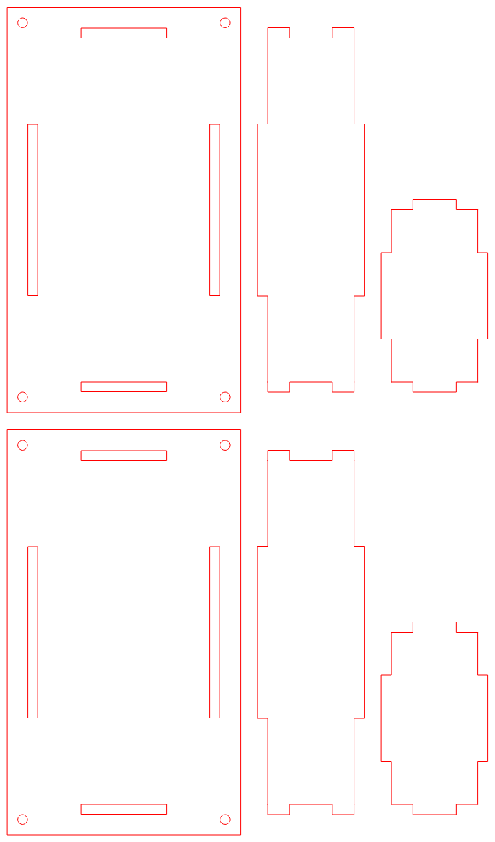
For 150 lines of code I now have this:
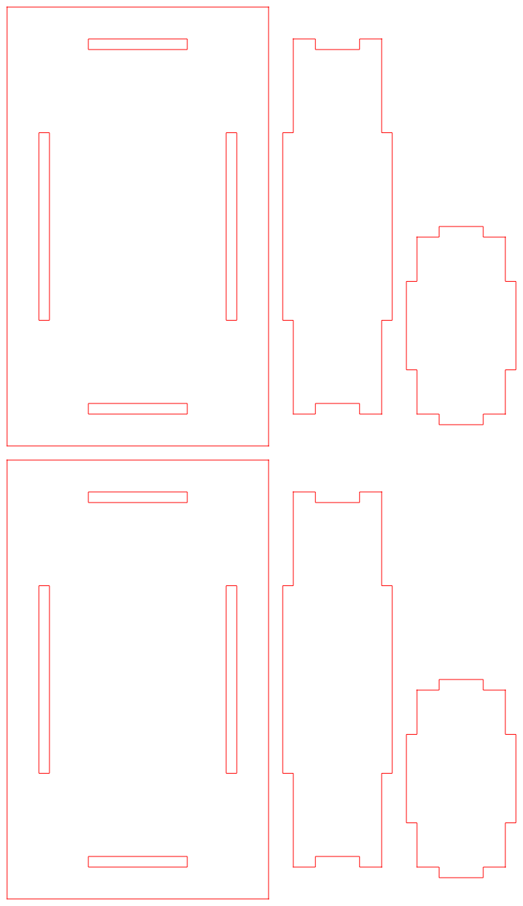
Next is to add:
- Boltholes
- Kerf for the laser option
- Corner holes for the CNCmill option
Finally
Ran into a problem with the data structure. While the dxf requires points, the graphic uses segments (uses two points), the offset routine requires triplets (three points). It was getting messy.
Two options, hard code the offsets or sort out the problem. As a polyline offset routine would be handy I persisted.
First I had to get a general polyline offset routine working. That requires and intersection routine. That is not too hard:
bool intersect(double px0,double py0,double px1,double py1,double px2,double py2,double px3,double py3,double *px,double *py) {
  double det,s,t;

  det=(px1-px0)*(py3-py2)-(px3-px2)*(py1-py0);
  if (fabs(det)>1e-6) {
    s=((px1-px0)*(py0-py2)-(py1-py0)*(px0-px2))/det;
    t=((px3-px2)*(py0-py2)-(py3-py2)*(px0-px2))/det;
    if ((s>=0.0)&&(s<=1.0)&&(t>=0.0)&&(t<=1.0)){
      *px=px0+t*(px1-px0);
      *py=py0+t*(py1-py0);
      return true;
    }
  }
  return false;
}
Nest the offset routine. Now I know this mus be hard as most CAD packages have problems here with polylines that "ill formed". Actually, not hard, the time was spent working out what to do with the non-intersecting segments.
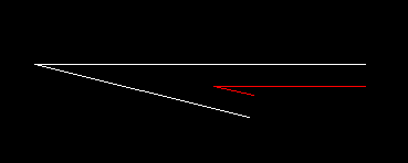
Here is the first case where I have trimmed the intersection lines:
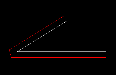
Here is the second case where segment intersection works:
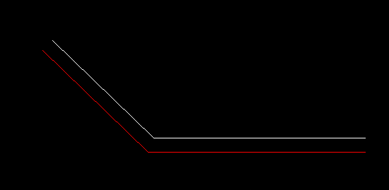
And again:
Now the problem case:
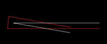
Although it looks bad it is actually okay. This is where I wasted a lot of time trying to fix.
Yes the offsets will intersect later, but that needs to be trimmed (if required) in another sub-routine.
Another compromise was not to offset for kerf the graphical display. It just save headaches and add no real value.
Here is the offset code:
void makeOutline(FILE *F1,double x1,double y1,double xc,double yc,double x2,double y2,double Offset)
{
  double dx1,dy1,dl1,xo1,yo1,xc1,yc1;
  double dx2,dy2,dl2,xo2,yo2,xc2,yc2;
  double xi,yi;

  dx1=xc-x1;
  dy1=yc-y1;
  dl1=sqrt(dx1*dx1+dy1*dy1);
  dx2=xc-x2;
  dy2=yc-y2;
  dl2=sqrt(dx2*dx2+dy2*dy2);

  if ((fabs(dl1)>1e-6)&&(fabs(dl2)>1e-6)) {
    dx1=dx1/dl1*Offset;
    dy1=dy1/dl1*Offset;

    dx2=dx2/dl2*Offset;
    dy2=dy2/dl2*Offset;

    xo1=x1-dy1;
    yo1=y1+dx1;
    if (Offset>=0.0) {
      xc1=xc-dy1+dx1;
      yc1=yc+dx1+dy1;
      xc2=xc+dy2+dx2;
      yc2=yc-dx2+dy2;
    } else {
      xc1=xc-dy1-dx1;
      yc1=yc+dx1-dy1;
      xc2=xc+dy2-dx2;
      yc2=yc-dx2-dy2;
    }
    xo2=x2+dy2;
    yo2=y2-dx2;

    if (intersect(xo1,yo1,xc1,yc1,xc2,yc2,xo2,yo2,&xi,&yi)) {
      // Test good, use intercept
      DXF_PolylinePoint(F1,xi,yi,0.0);
    } else {
      // Test failed, improvise
      DXF_PolylinePoint(F1,xc1,yc1,0.0);
      DXF_PolylinePoint(F1,xc2,yc2,0.0);
    }
  }
}
So all done.
Other Options
Anything that easy to do in QCAD I will leave for QCAD. But adding a basic partition (dividing the length direction in two) seems useful. Once in QCAD it can be moved and duplicated. Another option is a false floor.
Finished
I have finally finished. Cleaned up the code (a little easier to add options). Added the partition options.
Here is the Dialog:

And the default DXF:
And a Mill option with a height partition (i.e. a false floor):

All done, uploaded the files.
AlanX
Discussions
Become a Hackaday.io Member
Create an account to leave a comment. Already have an account? Log In.
Yes, it escaped me at the time. I will change the title.
Nearly done, just the kerf and drill holes to do.
AlanX
Are you sure? yes | no
The design technique is called divide and conquer. Recursion is when a procedure calls itself.
Are you sure? yes | no