 Eric
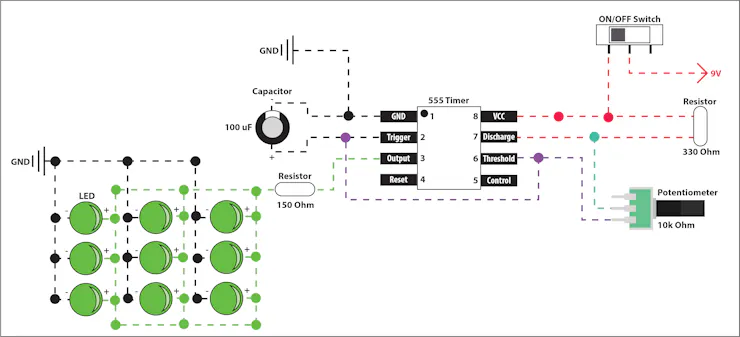
EricThis 555 timer circuit utilizes the astable operating mode with a 10k potentiometer to adjust the speed of the flash.
0%
0%
Handheld Party Starter Pocket Strobe
Giving you that little bit of oomf you need to kick any situation up a notch.
Become a Hackaday.io member
Already have an account? Log in.
Just one more thing
To make the experience fit your profile, pick a username and tell us what interests you.
Pick an awesome username
hackaday.io/
Your profile's URL: hackaday.io/username. Max 25 alphanumeric characters.
Pick a few interests
Projects that share your interests
People that share your interests


 You can really make it whatever size/shape you want but I was going for a Men in Black Neuralyzer feel.


 Gregory
 sarah boo
 Kelly Heaton
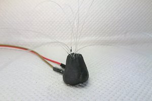
 blorgggg
Ahhh I wish the Othermill at the office was working :(