 Sander van de Bor
In our world we use clocks to keep track of time and in the micro-controller world we use timers to count the clock. Clocks used in microcontrollers do not keep track of time!
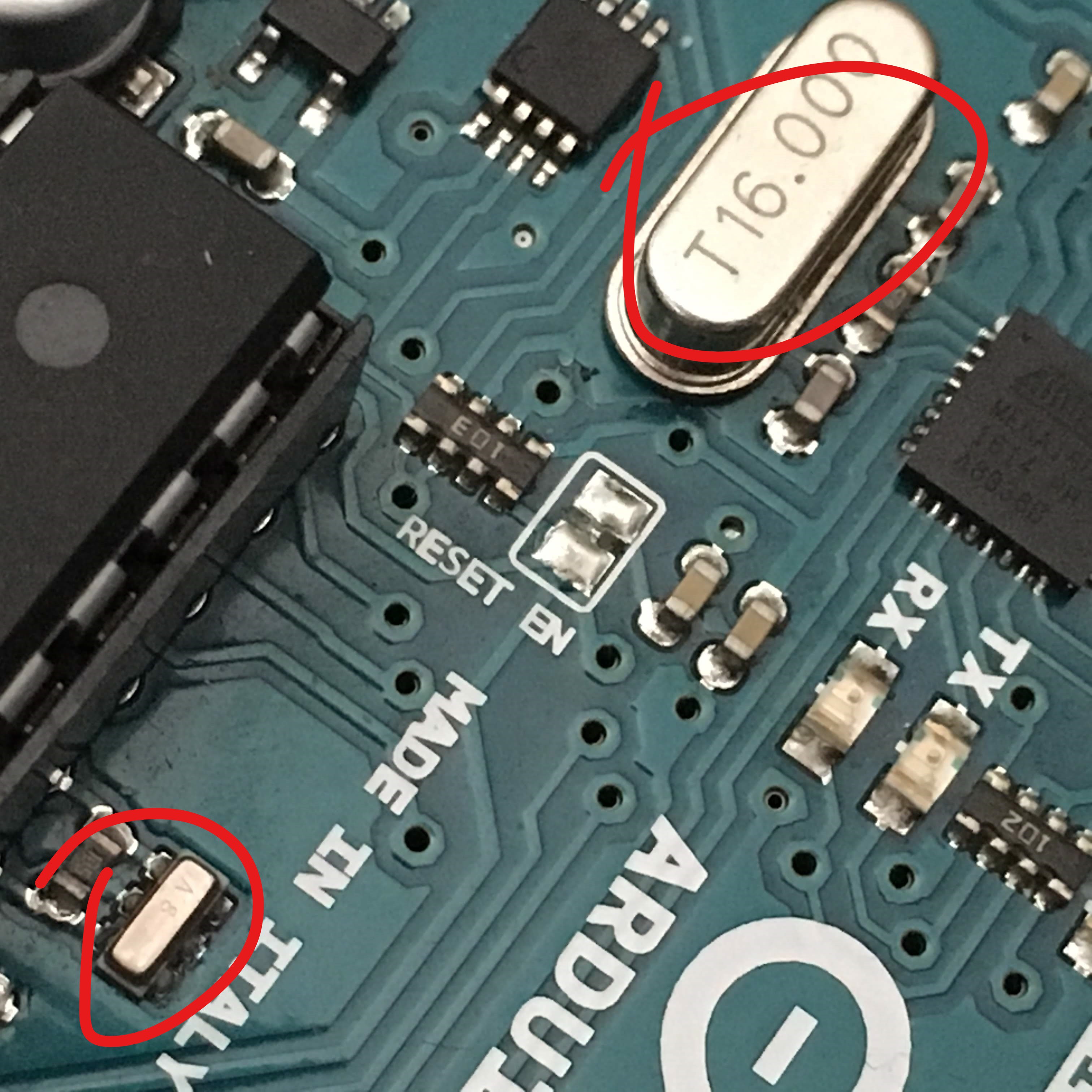
Timers on the micro-controller can be confusing and could be hard to understand but are so important for the microcontroller to operate. For example, when we like to flash a single LED every 500 millisecond, then we must keep track of time somehow. Almost every micro-controller out there has at least one or two timers, the ATtiny84a had 2, the ATtiny1616 has 4. But a timer will not count (the method to keep track of time) by itself. It needs an input, a source from something that pulses, called a clock. The most common clock is an oscillator and some microcontrollers have some build in. Most of the older controllers uses external oscillators for a better accuracy, for example the Arduino UNO has two:
Fortunately, the ATtiny has internal oscillators that are sufficient for most project. The internal oscillator for the Attiny84a used to be calibrated for 8MHz, this new ATtiny1616 uses a 16/20 MHz low-power RC oscillator.
These clocks are used as an input to the timers and currently configured as follows (taken from the Atmel Start application):
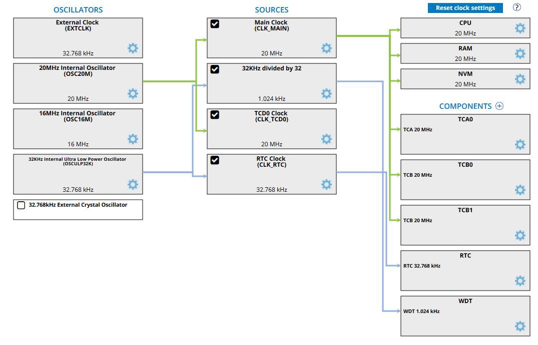
On the left you see the different oscillators, where the 3 options in the middle (20MHz, 16MHz and 32KHz) are internal and the other two external. In the middle are the sources, where the clock can be manipulated before getting used. For example, the Main Clock can be divided by 2 which will result in a 10MHz source for peripherals on the right (and the CPU will run only at half the speed). Running the CPU at a slower speed can help to reduce the power consumption.
Under components you see the actual timers used by the micro-controller, and if you are paying attention you might notice that there are 5 timers listed, not 4 I mentioned above. It gets even more complicated! According to the ATtiny1616 spec sheet there are 4 timers: Timer/Counter Type A (TCA0), Timer/Counter Type B (TCB0 and TCB1), and the fourth Timer/Counter Type D (TCD0). TCD0 is actually listed under sources, probably because it is always active while the other components could be turned off (and they do not appear on the picture above).
The WDT is the Watch Dog Timer. Yes, it is a timer, but cannot be used to execute some code on the ATtiny1616. The WDT can only be used to reset the microcontroller when it gets stuck in some code (an infinite loop).
RTC is the real time counter. It is not a timer, it is a time counter. To be honest that confuses the heck out of me as well. The RTC is actually a great counter which you will appreciate for your low power consumption projects. On the older ATtiny’s the WDT could be used to wake-up the micro-controller, but that is not longer an option on the ATtiny1616; it is done with the RTC.
You can see above that almost all the timers use the 20MHz oscillator. The 20MHz is accurate (±2%), but will use some power to run it. The RTC and WDT are using the 32.768 kHz (note it can be written as 32Khz as well which is 32khz*1024), which is slow and not so accurate (±10% when not calibrated), but the power consumption is very low! It is also a timer which is probably not going to be used by anything else on the Arduino, so it will be available without any interference with other existing code.
In this example I am going to demonstrate how to use RTC to blink an LED, the “hello world” of the Arduino. I will introduce some new instructions which can be used.
We probably all know how to make an LED blink in Arduino, there is even an example in the IDE called blink:
void setup() {
  pinMode(LED_BUILTIN, OUTPUT);
}

void loop() {
  digitalWrite(LED_BUILTIN, HIGH);   // turn the LED on (HIGH is the voltage level)
  delay(1000);                       // wait for a second
  digitalWrite(LED_BUILTIN, LOW);    // turn the LED off by making the voltage LOW
  delay(1000);                       // wait for a second
}
I used to replace the loop with the following code, and it was possible since HIGH and LOW were just a BOOL of 0 or 1, to make it shorter:
digitalWrite(LED_BUILTIN, digitalRead(LED_BUILTIN));   // turn the LED on  or off based on previous state
delay(1000);                       // wait for a second
That no longer works with the new core since it has some more options besides HIGH and LOW, CHANGE can be used to toggle the output, resulting in:
digitalWrite(LED_BUILTIN, CHANGE);   // toggle the LED
delay(1000);                         // wait for a second
Running this code will result, as expected, with an LED to turn on and off using PIN#4.
Using delay is convenient, but it has a big disadvantage, the CPU cannot do something else at that moment. It is basically checking (for thousands of cycles) if it reached to set delay time. So the CPU is wasting energy on nothing at that moment.
There are tons of examples out there that use millis, but there is an even better solution by using RTC. Page#317 of the ATtiny1616 manual describes how to use it: http://ww1.microchip.com/downloads/en/DeviceDoc/ATtiny3216_ATtiny1616-data-sheet-40001997B.pdf
23.3.1.1 Configure the Clock CLK_RTC, step 1 and 2 will result in the following code when we want to use the 32KHz internal oscillator.
RTC.CLKSEL = RTC_CLKSEL_INT32K_gc; // 32.768kHz Internal Crystal Oscillator (INT32K)
23.3.1.2 Configure RTC for operating the RTC where we set the delay in step 1, enabling interrupts in step 2 and setting a prescaler in step 3. A prescaler is used to slow down the clock we are using. For example, we use the 32.768kHz clock, but we only want to do a delay where the shortest period is 1ms, which we get by using the divider 32. We could have left the divider at 1, and count up to 32768 to get to one second instead, but using 1000 for 1 second is easier work with. Using the prescaler also helps with longer delays since we only have 16 bits to count with, so we can only count to 65536. Without the prescaler we can count to 65536/32768 = 2 seconds max! With the prescaling of 32 this number will increase to 64 seconds, just over a minute. For very slow applications (for example you just want to measure something once an hour) you can use a prescaler of 32,768 (15 bits max), which will result in 1 second minimum delay and 18 hours max. In our case the next registers are set as follows:
  RTC.PER = RTCdelay;                   // Set period for delay
  RTC.INTCTRL |= RTC_OVF_bm;            // Enable overflow Interrupt which will trigger ISR
  RTC.CTRLA = RTC_PRESCALER_DIV32_gc    // 32768 / 32 = 1024 (sec) ~ 1 ms
  | RTC_RTCEN_bm                        // Enable: enabled
  | RTC_RUNSTDBY_bm;                    // Run In Standby: enabled
Please pay close attention to the note at the end of 23.3.1.2 where it mentions to check the busy bits which we do as follows:
while (RTC.STATUS > 0);
The RTC will create an interrupt as soon as the RTC.PER is reached, and the Interrupt Service Routine (ISR) uses the following vector from the RCT: RTC_CNT_vect. In that interrupt we can add our action, in this case toggling the LED. Also make sure to set the RTC counter back to zero as follows:
ISR(RTC_CNT_vect)
ISR(RTC_CNT_vect)
{
  RTC.INTFLAGS = RTC_OVF_bm;            // Clear flag by writing '1':
  digitalWrite(LED_BUILTIN, CHANGE);
}
As a result, there is nothing left in the loop! The CPU has nothing to do till it gets the interrupt. There is still one issue, the CPU is busy with doing nothing and still using a lot of power doing so. In the next chapter I will explain how to give it a break to take a nap.
See here the complete code for using RTC in Arduino:
void RTC_init(int RTCdelay)
{
  RTC.CLKSEL = RTC_CLKSEL_INT32K_gc;    // 32.768kHz Internal Crystal Oscillator (INT32K)

  while (RTC.STATUS > 0);               // Wait for all register to be synchronized
  RTC.PER = RTCdelay;                   // Set period for delay
  RTC.INTCTRL |= RTC_OVF_bm;            // Enable overflow Interrupt which will trigger ISR
  RTC.CTRLA = RTC_PRESCALER_DIV32_gc    // 32768 / 32 = 1024 (sec) ~ 1 ms
  | RTC_RTCEN_bm                        // Enable: enabled
  | RTC_RUNSTDBY_bm;                    // Run In Standby: enabled
}

ISR(RTC_CNT_vect)
{
  RTC.INTFLAGS = RTC_OVF_bm;            // Clear flag by writing '1':
  digitalWrite(LED_BUILTIN, CHANGE);
}

void setup()
{
  pinMode(LED_BUILTIN, OUTPUT);
  RTC_init(1000);   // Start the RTC time counter, counting up to 1000 (~1 sec.)
}

void loop()
{
  // nothing to do here
}
Discussions
Become a Hackaday.io Member
Create an account to leave a comment. Already have an account? Log In.