 Sander van de Bor
We probably all got to a point where we must start using a multi-meter to analyze our circuit, and very often we want to measure the voltage. Putting one of the probes on voltage source will not give us any feedback, the second must be connected to a reference and in most cases that will be the ground.
Analog-to-digital converters (ADC) work very similar. They can take a voltage, for example from one of the pins, and calculate a difference to another reference. There is just one little difference here. The voltage we like to measure must be lower than the voltage on the reference. For example, when we like to measure 5V, we need at least 5V as a reference. Reason is that we are measuring a fraction as follows: Vin / Vref. So when Vin is 5V, and Vref is 5V, we will get 1 back. On the other hand when Vin is 1V, and Vref is still 5, we will get 0.2 as a result.
So the ADC calculates a fraction, but the microcontroller cannot hold fractions, it calculates in bits. The ATtiny is using a 10 bit register to hold this value between 0 and 1 using these 10 bits. In decimals 10bits can hold a value of 2^10 – 1024, but since we start at 0 the maximum decimal value is 1023. Using that conversion, to go from a fraction to bits, will result in the following equation:
You can find some information on this equation in the data sheet on page#485:
http://ww1.microchip.com/downloads/en/DeviceDoc/ATtiny3216_ATtiny1616-data-sheet-40001997B.pdf
If the Vin is above Vref, for example Vin is 5.5V and Vref is still 5, the ADC will result with the maximum 10bits value of 1023. According to the equation this should result in 1125, but since we can only have 10 bits we will only get a value up to 1023 instead.
Most used Vin is the analog input pin, on the Arduino UNO pins A0 to A5, and the Vref will be the applied voltage (3.3V or 5V). But there are tons of more combinations possible! Lets start with Vin on page# 495 of the datasheet. This is very similar to the PORTMUX where from an earlier log where we told the controller which serial ports we like to use. In this case we must tell the ADC what we like to convert. Starting at the top you can find AIN0 which the Analog Input Channel linked to a pin (explained in the previous log). Besides the pins we also have other options starting at 0x1B. PTC, DAC0, INTREF and GND. Later I will show an example where we can use these.
Secondly, we need the V reference and there we have tons of options as well. You will find those on page#491 Bits 5:4 REFSEL. It will get a little bit confusing here! There is not just one Vref. There is one for the ADC, DAC and the AC. so from now on I will call it ADC0.Vref. As you can see there are only 3 options for the reference. INTERNAL, VDD and VREFA. VDD is the applied voltage, so when you apply 5V to the microcontroller, VDD is 5V. Another option is applying an external voltage on VREFA, which is located on pin#1 in this situation. VREFA has nothing to do with VREF, it is just another reference for the ADC. The INTERNAL option is even more interesting. It uses the internal reference voltage of the chip, Vref, but again has nothing to do with ADC0.Vref, unless this INTERNAL option is selected. The Voltage Reference VREF is explained in chapter 18 where you see that it has 5 different settings:
- 0.55V
- 1.1V
- 1.5V
- 2.5V
- 4.3V
Using the INTERNAL voltage reference can be helpful when you VDD is not consistent but you want a consistent reading from an external voltage source.
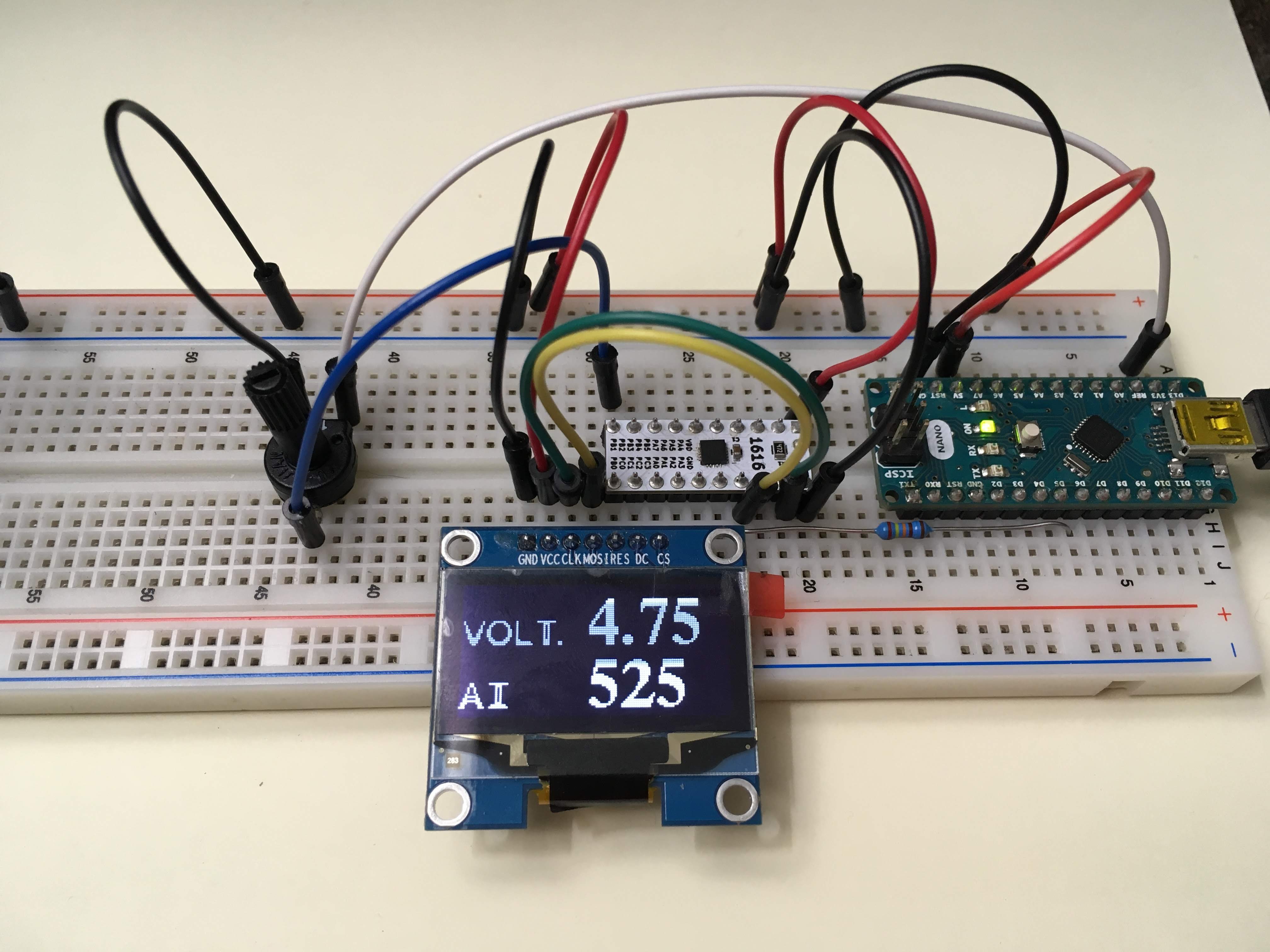
In the following examples I will use a super capacitor as a power source to the ATtiny1616. The voltage from the super capacitor will drop as soon as it disconnects from the 5V source used to charge the super capacitor. Measuring the incoming voltage on the ADC from different sources requires different solutions as follows:

Reading a potmeter attached to VDD. This is very common when using the Arduino. When we turn the pot right in the center, we will get 2.5V when we use a 5V source, but only 1.65V when we use 3.3V. This will result in the following:
And for the 3.3V version:
That is great! The actual analog reading is not changing when the voltage is changing, but there are other situations, for example: We have a voltage coming in from another device telling us the temperature by sending a voltage between 1-4V. Before we used Vref (the VDD) as a reference for the analog input, but our VDD voltage is dropping from 5V to 3V, this will result in reading higher values coming in till the VDD drops below the incoming voltage and it only reads 1023 max. For example, we have a constant 2.5V provided by a sensor, resulting in the following reading when the super capacitor is fully charged:
But now our voltage is dropping, till 1.8V and the microcontroller will turn off, results into the following reading:
Since 1420 is above 1023, the actual reading of the analog input will be 1023. The actual readings are changing constantly as shown in the video below:
So in order to get a stable reading we must change the ADC0.Vref to INTERNAL and pick one of the voltage references, in this example 1.1V. In Arduino the following command will do both:
analogReference(INTERNAL1V1);
analogReference(INTERNAL1V1);
other options are:
INTERNAL0V55
INTERNAL1V1
INTERNAL2V5
INTERNAL1V5
INTERNAL4V3
VDD
EXTERNAL
We are going to use 1.1V as the reference since we know that the voltage supplied by the super capacitor will drop as low as 1.8V, which is the minimum voltage requirement for a stable Vref of 1.1V. All the higher voltages will be useless when the VDD gets that low. But the analog input is still reading 2.5V, resulting in:So in order to use the internal reference we have to use a voltage divider to make sure the voltage on the analog input is below the internal voltage.
I use a potentiometer on the incoming voltage to bring it down to a usable reference voltage, in this case down to 0.56V:
Discussions
Become a Hackaday.io Member
Create an account to leave a comment. Already have an account? Log In.