 Sander van de Bor
The ATtiny micron-controllers are very popular in the makers community. Only a single capacitor is recommended to stabilize the incoming power and different power sources between 1.8V to 5.5V can be used. The 8MHz internal oscillator will work for most projects and at a cost of about $1 for the DIP version it can be integrated into a project for a fraction of a full blown Arduino UNO.
In order to program micro-controllers programmers are used and offered by the manufactures from these chips. The cost of these programmers start around $50 and can go up to a couple hundreds of dollars. While these programmers are great, and excellent for debugging as well, it is a cost that most makers are not willing to spend. Fortunately the Arduino platform offered a solution where the Arduino UNO can be programmed with a sketch to operate as an SPI programmer. Using the MOSI, MISO, SCK and reset lines allowed uploading sketches through the Arduino UNO to the ATtiny-AVR.
The new ATtiny1616 is a little bit different, and the SPI programmer for the ATtiny-AVR will no longer work. These so called tinyAVR® 1-Series, and similar to the tinyAVR® 0-Series and the megaAVR® 0-series, are using the UPDI 1-wire interface. This new protocol sound very promising since it only requires 1 pin to communicate instead of the 4 pins for SPI and fortunately an Arduino is already there!
El Tangas created a great solution (which can be used on the Arduino UNO) to turn most common Arduino devices into UPDI programmers. The code can be found on Github;
https://github.com/ElTangas/jtag2updi
While a like using the Arduino UNO (I have done all my ATtiny84a projects with the UNO) it is often bulky and requires a lot of wires. An alternative solution is upgrading a AVR JTAG ICE clone with new firmware per following instructions:
https://github.com/ElTangas/jtag2updi/tree/master/tools/avrjtagicev2
The 10 pin ribbon cable is great, because you can press 1.02 diameter pogo pins into the end.
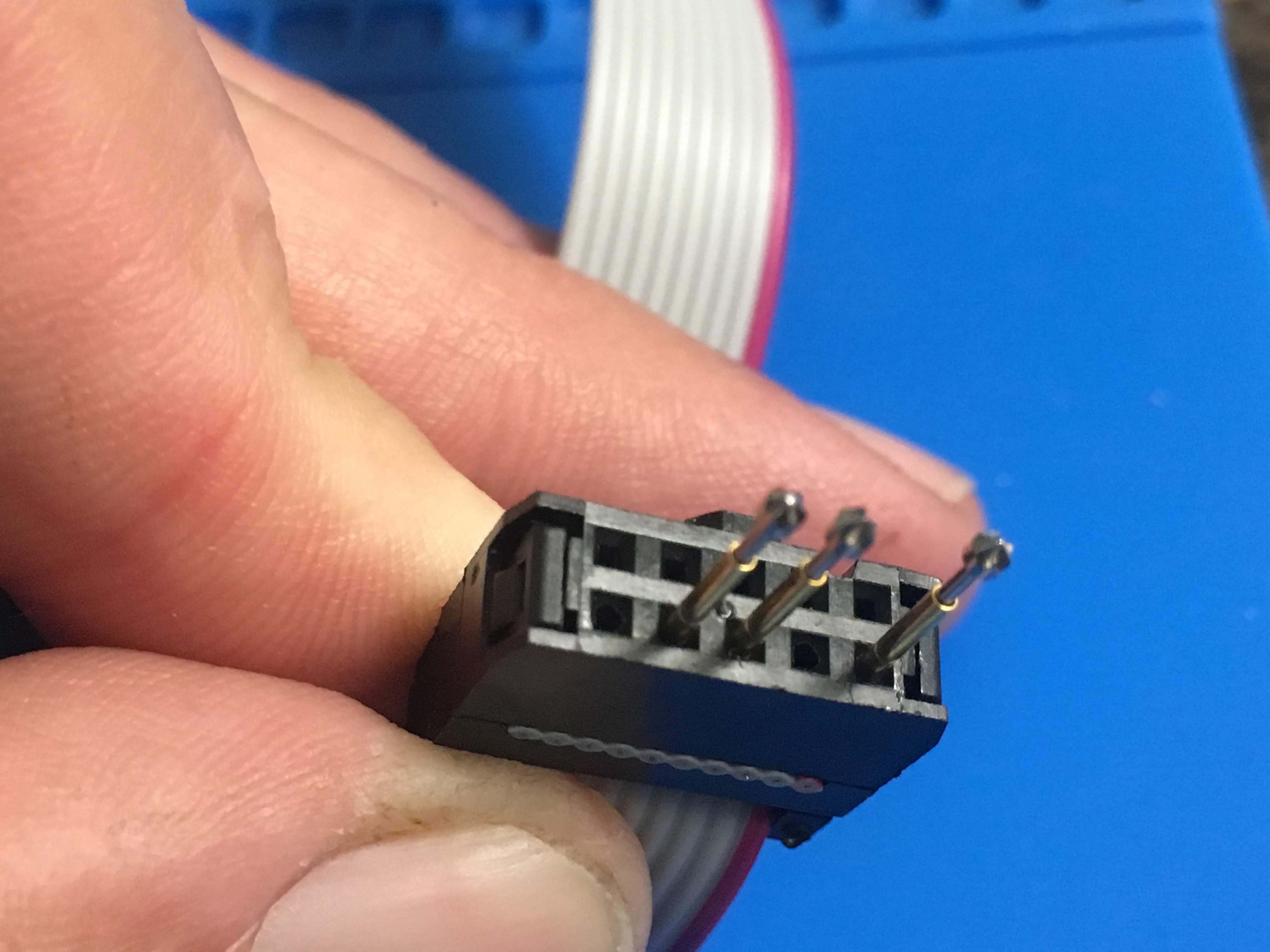
It is very similar to the SEGGER pin needle adapters used for programming, but only at a fraction of the cost. While El Tangas shows connecting pin#2 to GND pin#4 for VCC and #6 for UPDI, I decided to use pin #10 for ground instead for the following reasons:
- The DIP break out board for the ATtiny1616 must fit on the bread board, and the VCC and GND need 4 pins spacing between each other, which I get by having VCC on pin #4 and GND on pin #10
- Having the 3 pins separated by an empty pin generates a key so that connecting it to the board will only fit one way (originally the 3 pins were next to each other, so VCC and GND could easily be swapped.
Here is a picture of how this is applied to the board:
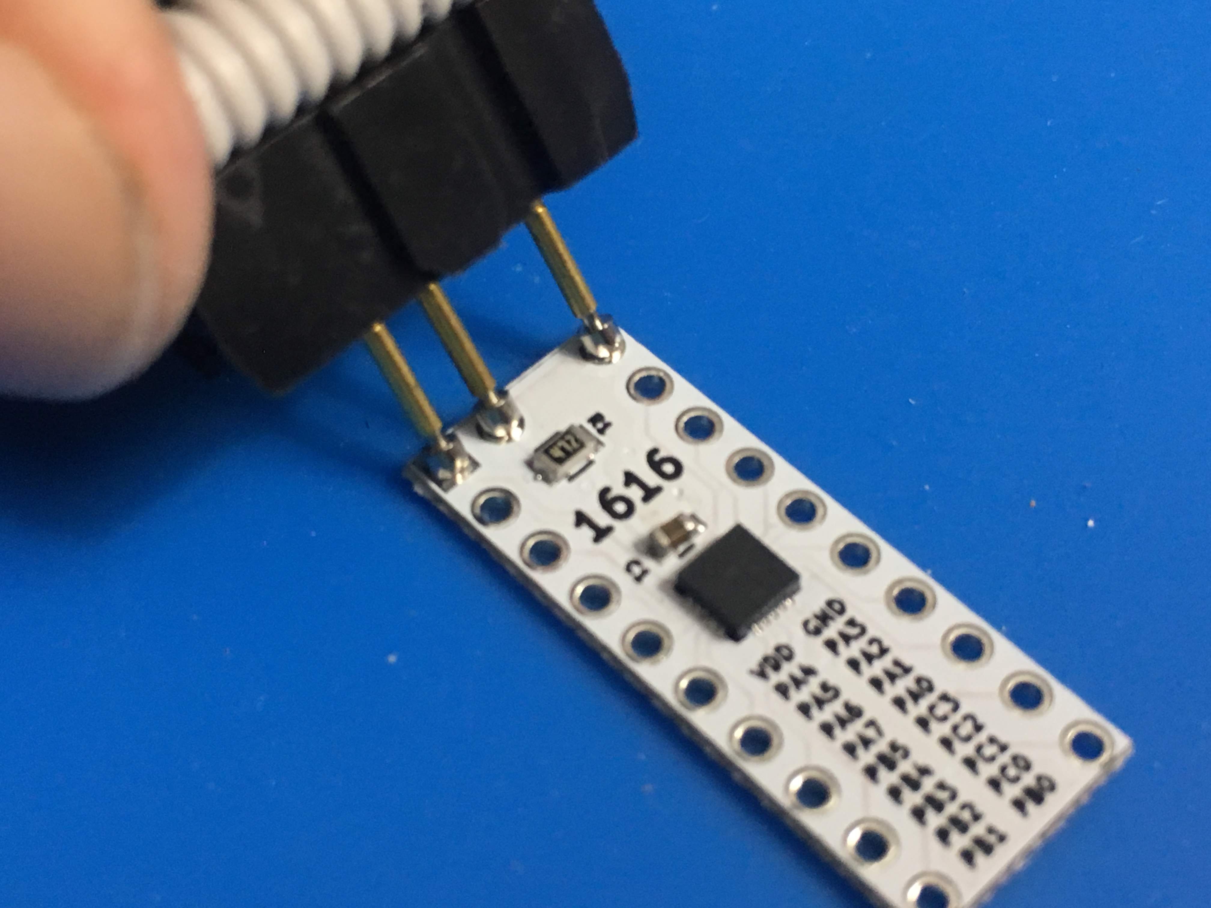
With the pogo pins it is even possible to connect when header pins are applied:

Next will be the design of the break-out board.
Discussions
Become a Hackaday.io Member
Create an account to leave a comment. Already have an account? Log In.