 Sander van de Bor
The Arduino IDE is great for a quick and easy sketch, but since not all functions of the 0- and 1- series are implemented (yet), we have to dig into the datasheet and write some code ourselves. For example, interrupts! It is pretty easy to setup a pin interrupt in Arduino and in a previous log I also showed an interrupt with the Real Time Counter (RTC), but the ATtiny1616 can actually create interrupts on almost every peripheral.
Peripherals are used to offload the MCU. For example, you can be in the office checking the desk phone every 10 seconds to make sure nobody is on the other side of the line, but you will get no other work done. Instead the phone rings when someone is calling you, and at that moment they will interrupt the task you were doing and you pick up the phone.
The microcontroller works the same way. It has peripherals that can do certain tasks and they will only notify the MCU when input from the MCU is required, or when they are done with that task. It is even possible for peripherals to do certain tasks after each other without the MCU involved! On the ATtiny this is done through the event system.
All peripherals and matching interrupts can be found on page#45 of the datasheet (table 7-2). Besides the interrupts for the PORTA to PORTC, and the timers RTC and TCA up to TCD, interrupts are available for the analog I/O and communication peripherals like TWI0 (Wire), SPI and UART (Serial).
I am very interested in powering my next projects with super capacitors and I got myself one of these 5.5V 4F coin size capacitors that I am going to use for this next experiment. Super capacitors could be the power storage for many devices in the future, but at this moment the capacity is too low, and you must work around a gradual voltage loss while using it. I like to know how long I can power the ATtiny1616 from a super capacitor in the following modes:
- CPU running at 20MHz
- CPU running at 3.33MHz
- CPU running at 1MHz, and use sleep mode
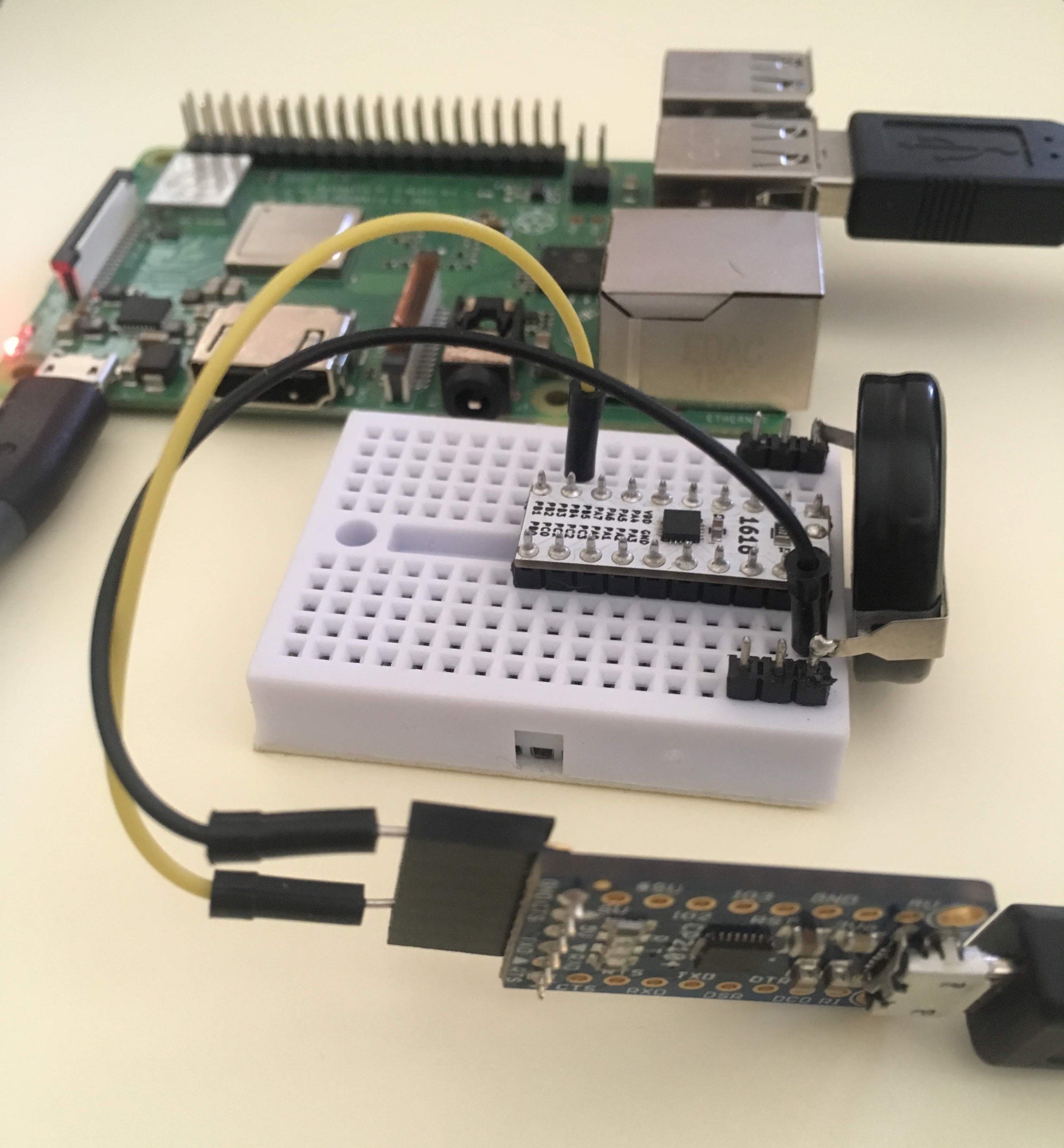
To measure the differences in power consumption I will use a program on the ATtiny1616 which will measure the voltage supplied by the super capacitor every second and reports this back using the serial port. The serial port is connected to a Raspberry Pi which will record the readings. The program will be written for the sleep mode, but the sleep mode will not be used when testing for 20MHz and 1MHz.
The program will have the following flow:
- Interrupt from the PIT once a second to start the cycle (ISR(RTC_PIT_vect))
- Start ADC conversion to read internal voltage. It will take a couple clock cycles to get the actual reading.
- Sleep CPU
- Interrupt from the ADC results ready (ISR(ADC0_RESRDY_vect))
- Convert the results to an actual voltage
- Send the information using UART0
- Wait for the transmit to complete (wait for TXCIF flag)
- Clear the TXCIF flag
- Sleep CPU
I could have entered sleep mode after sending the information using UART and have an UART interrupt triggered after the message was completely send. Or just skip checking for a complete message entirely, but this check is important in case you want to turn off the transmitter and activate the receiver instead when you use the line both ways.
The while(1) is the main loop (like loop() in Arduino) and will have sleep_cpu() to enter sleep mode. This is commented out when the CPU is tested at 20 and 1MHz.
Here is the complete code. I haven’t ported this to Arduino yet and used Atmel studio to compile this code:
#define F_CPU 1000000L
#define USART0_BAUD_RATE(BAUD_RATE) ((float)(F_CPU * 64 / (16 * (float)BAUD_RATE)) + 0.5)

#include <stdio.h>
#include <avr/sleep.h>
#include <avr/interrupt.h>

void RTC_init(void);
void USART0_init(void);
void CLKCTRL_init(void);
void ADC0_init(void);

static void USART0_sendChar(char c)
{
    while (!(USART0.STATUS & USART_DREIF_bm))
    {
        ;                                   /* Wait for USART ready for receiving next char */
    }
    USART0.TXDATAL = c;
}

static int USART0_printChar(char c, FILE *stream)
{
    USART0_sendChar(c);
    return 0;
}

static FILE USART_stream = FDEV_SETUP_STREAM(USART0_printChar, NULL, _FDEV_SETUP_WRITE);

void USART0_init(void)
{

    PORTB.DIR &= ~PIN3_bm;                  /* Configure RX pin as an input */
    PORTB.DIR |= PIN2_bm;                   /* Configure TX pin as an output */

    USART0.BAUD = (uint16_t)USART0_BAUD_RATE(9600);

    USART0.CTRLB |= USART_TXEN_bm;          /* Transmitter Enable bit mask. */

    stdout = &USART_stream;                 /* Bind UART to stdio output stream */
}

void CLKCTRL_init(void)
{
#if (F_CPU == 1000000L)                     /* 1MHz, 16/16, set fuse for 16MHz */
    _PROTECTED_WRITE(CLKCTRL.MCLKCTRLB, CLKCTRL_PDIV_16X_gc | CLKCTRL_PEN_bm);
#elif (F_CPU == 20000000L)                  /* 20MHz, no division */
    _PROTECTED_WRITE(CLKCTRL.MCLKCTRLB, 0 << CLKCTRL_PEN_bp);
#else                                       /* default 3.33MHz (20MHz/6) set fuse for 20MHz */
#endif
}

void RTC_init(void)
{
    /* Initialize RTC: */
    while (RTC.STATUS > 0)
    {
        ;                                   /* Wait for all register to be synchronized */
    }
    RTC.CLKSEL = RTC_CLKSEL_INT32K_gc;      /* 32.768kHz Internal Crystal Oscillator (XOSC32K) */

    RTC.PITINTCTRL = RTC_PI_bm;             /* Periodic Interrupt: enabled */

    RTC.PITCTRLA = RTC_PERIOD_CYC32768_gc   /* RTC Clock Cycles 32768, resulting in 32.768kHz/32768 = 1Hz */
    | RTC_PITEN_bm;                         /* Enable: enabled */
}

void ADC0_init(void)
{
    /* The App Note AN2447 uses Atmel Start to configure Vref but we'll do it explicitly in our code*/
    VREF.CTRLA = VREF_ADC0REFSEL_1V1_gc;    /* Set the Vref to 1.1V*/

    /* The following section is directly taken from Microchip App Note AN2447 page 13*/

    ADC0.INTCTRL = 1 << ADC_RESRDY_bp       /* Result Ready Interrupt Enable: enabled */
    | 0 << ADC_WCMP_bp; /* Window Comparator Interrupt Enable: disabled */

    ADC0.CTRLC = ADC_PRESC_DIV4_gc          /* CLK_PER divided by 4 */
    | ADC_REFSEL_VDDREF_gc                  /* Vdd (Vcc) be ADC reference */
    | 0 << ADC_SAMPCAP_bp;                  /* Sample Capacitance Selection: disabled */

    ADC0.CTRLA = 1 << ADC_ENABLE_bp         /* ADC Enable: enabled */
    | 0 << ADC_FREERUN_bp                   /* ADC Free run mode: enabled */
    | ADC_RESSEL_10BIT_gc                   /* 10-bit mode */
    | 1 << ADC_RUNSTBY_bp;                  /* Run standby mode: enabled */

    ADC0.COMMAND |= 1;                      /* start running ADC */
}

ISR(RTC_PIT_vect)
{
    ADC0.MUXPOS = ADC_MUXPOS_INTREF_gc;     /* ADC internal reference, the Vbg */
    ADC0.COMMAND = ADC_STCONV_bm;
    RTC.PITINTFLAGS = RTC_PI_bm;            /* Clear flag by writing '1': */
}

ISR(ADC0_RESRDY_vect)
{
    int Vcc_value = 0;                      /* measured Vcc value */
    /* ADC result ready interrupt handling: start USART transmission */
    Vcc_value = ( 0x400 * 1100L ) / ADC0.RES; /* calculate the Vcc value */
    printf("Counter value is, %u \r\n", Vcc_value);

    while (!(USART0.STATUS & USART_TXCIF_bm))
    ;                                       /* wait for USART TX complete */
    USART0.STATUS = USART_TXCIF_bm;         /* Clear TXCIF flag */

    ADC0.INTFLAGS = ADC_RESRDY_bm;          /* The interrupt flag has to be cleared manually */
}

int main(void)
{
    CLKCTRL_init();
    USART0_init();
    RTC_init();
    ADC0_init();

    sei();                                  /* Enable Global Interrupts */

    set_sleep_mode(SLEEP_MODE_STANDBY);     /* Set sleep mode to STANDBY mode */
    sleep_enable();

    while (1)
    {
        sleep_cpu();                        /* Nothing to do here */
    }
}
So my first test was at 20MHz and the test lasted 1320 seconds, or 22 minutes. Not very impressive, but looking at the datasheet, this was so short because of the following two reasons:
Power consumption at 20MHz and 5V is about 10ma, and down to 8 at 4.2V
Minimum voltage of 4.5V is required for 20MHz
According to the testing results I was actually down to 2.35V when it started acting up at 20MHz, but I should be able to go to a lower voltage when I use a slower CPU clock.
At 3.33MHz the test ran significant longer, 12838 seconds, or a little over 3 ½ hours. Big improvement was the power consumption at 5MHz which is only 2.6mA at 5V and below 1mA at 1.8V. The voltage can drop as low as 1.8V according to the datasheet. The results showed a lowest voltage of 1.7V.
In the last test I am going to use the sleep mode. According to the datasheet the power consumption can be as low as 0.1μA (all peripherals stopped at 3V), but we are still running the RTC in sleep mode which will add another 1.2μA.
The test took a long time, 121906 seconds! 1 day, 9 hours and 52 minutes. It did turn off around 1.7V again.
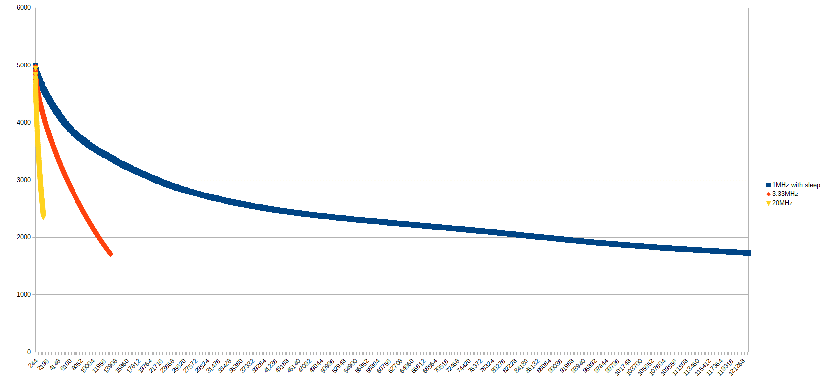
Graph of voltage readings from super capacitor: X=seconds, Y=mV
Using the sleep mode and interrupts made a huge improvement on the power consumption and now this super capacitor can be used for this micro-controller which can take measurements an entire day before another charge is required.
Discussions
Become a Hackaday.io Member
Create an account to leave a comment. Already have an account? Log In.