0%
0%
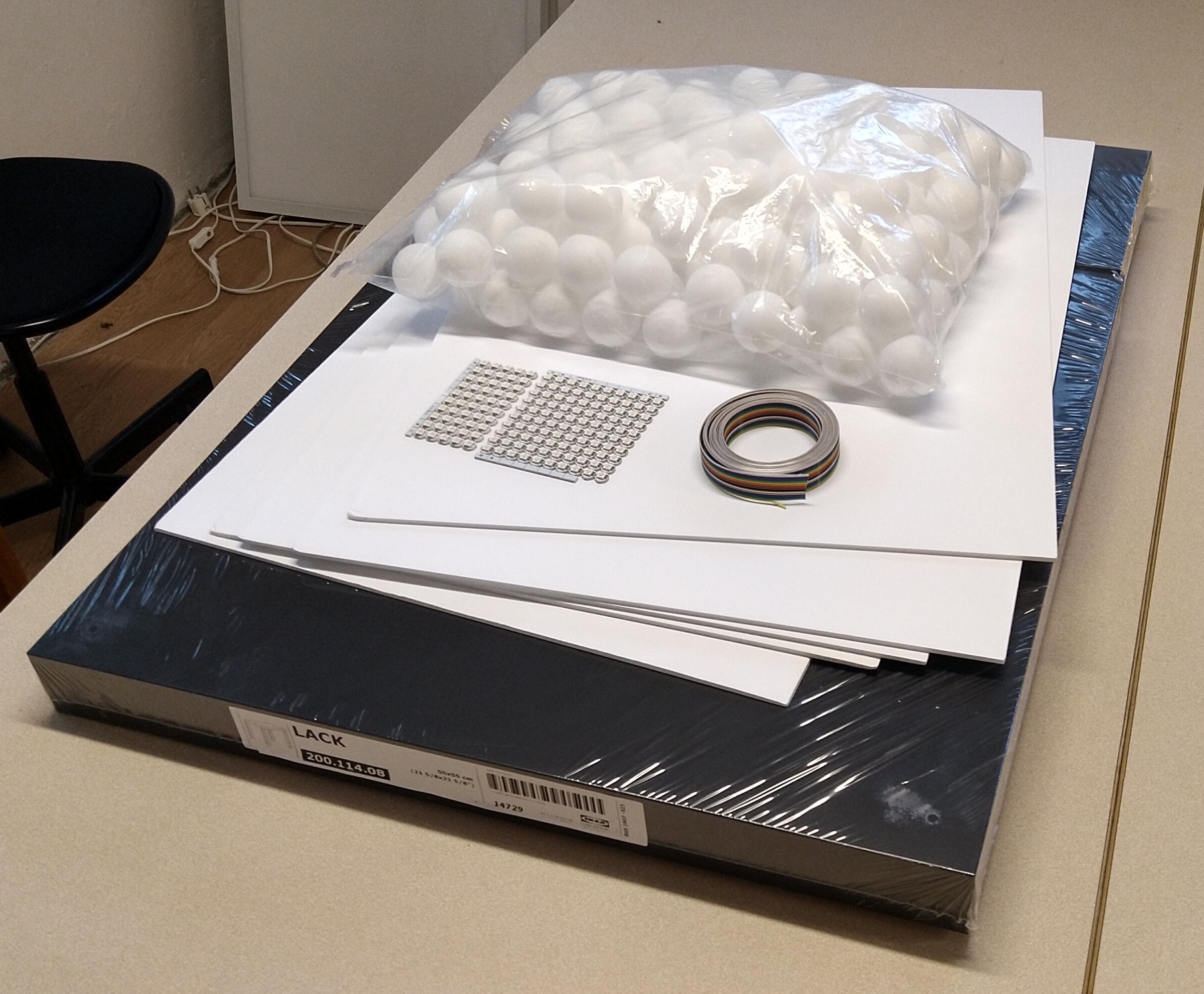
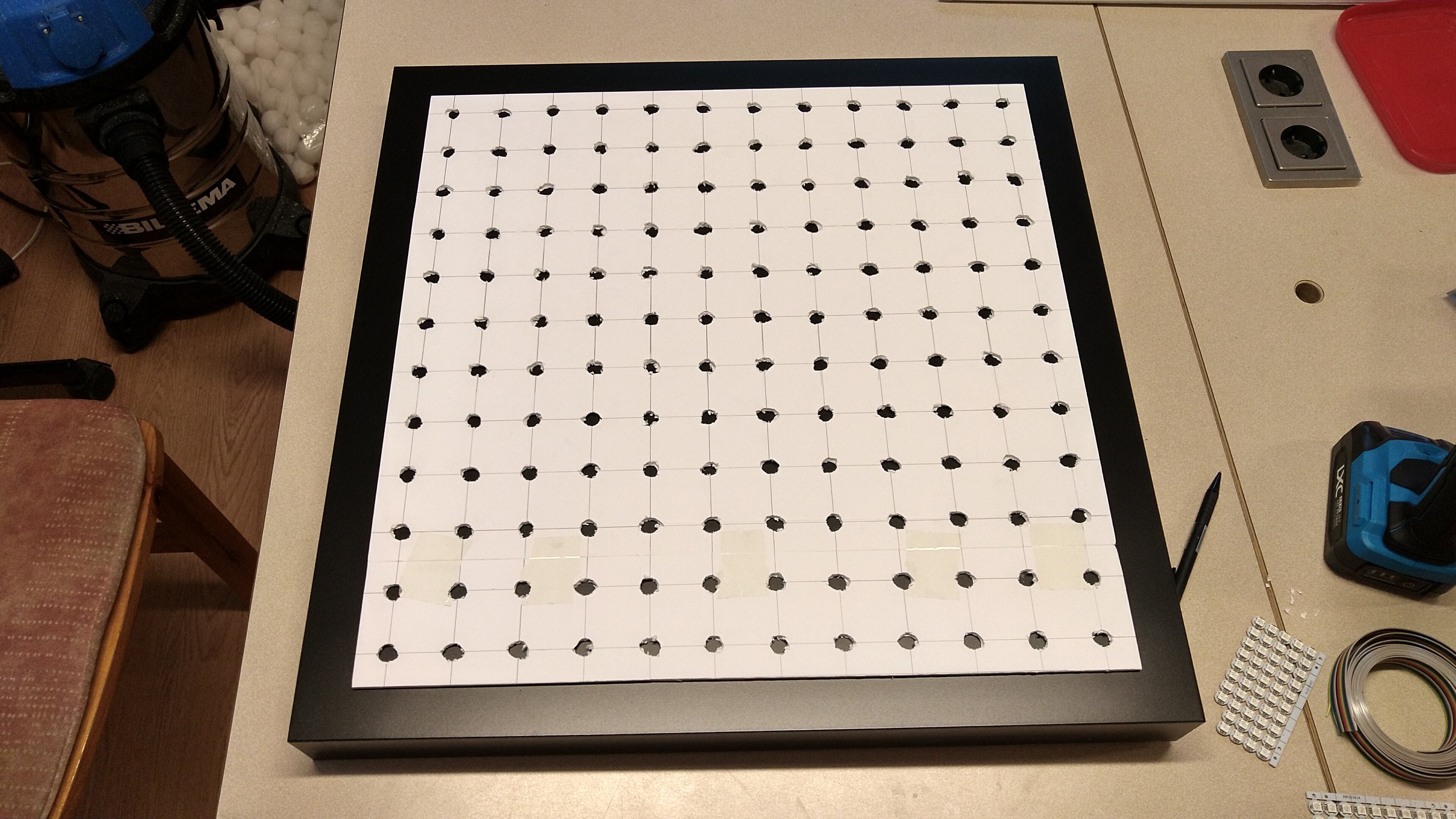
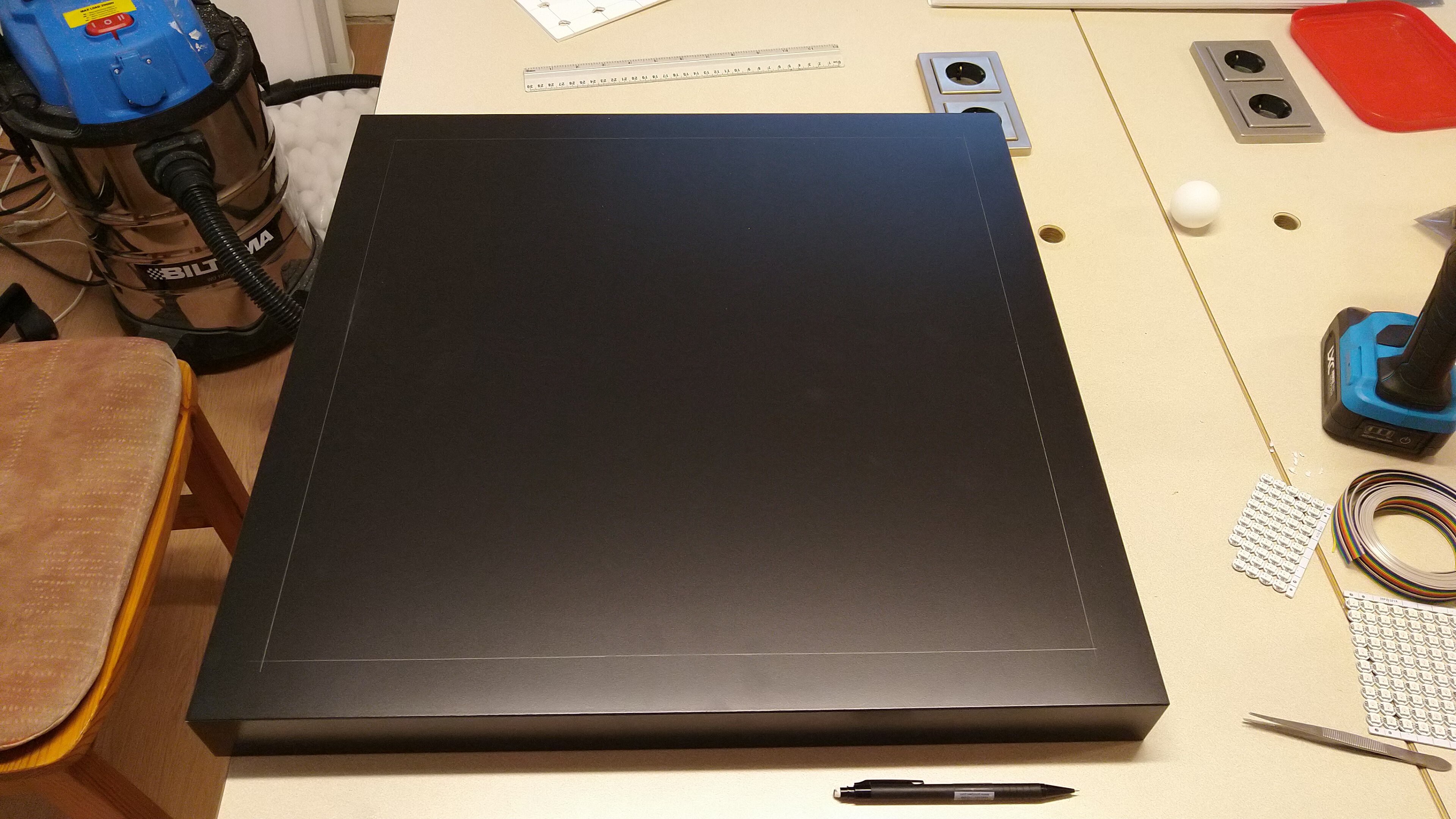
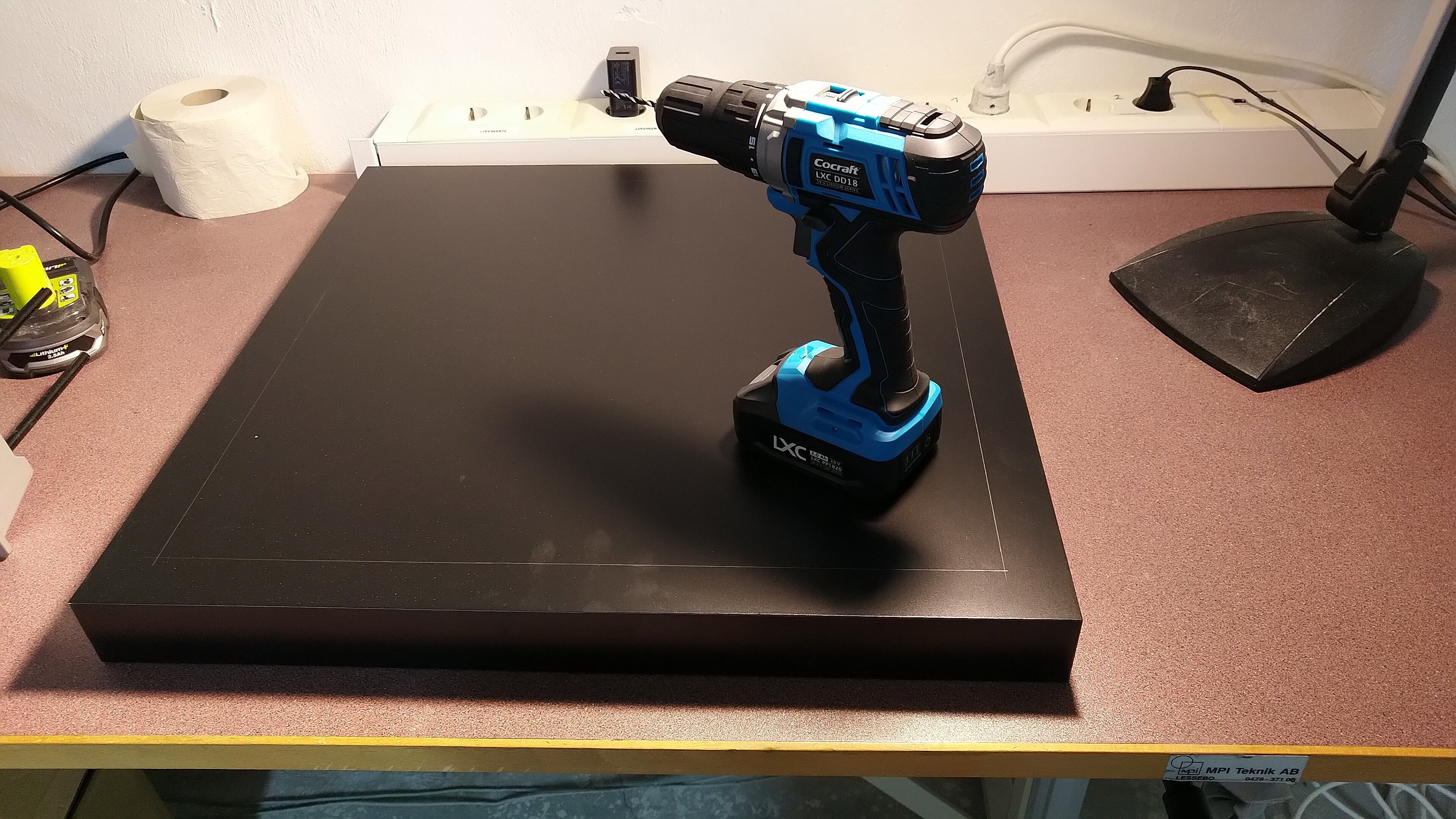
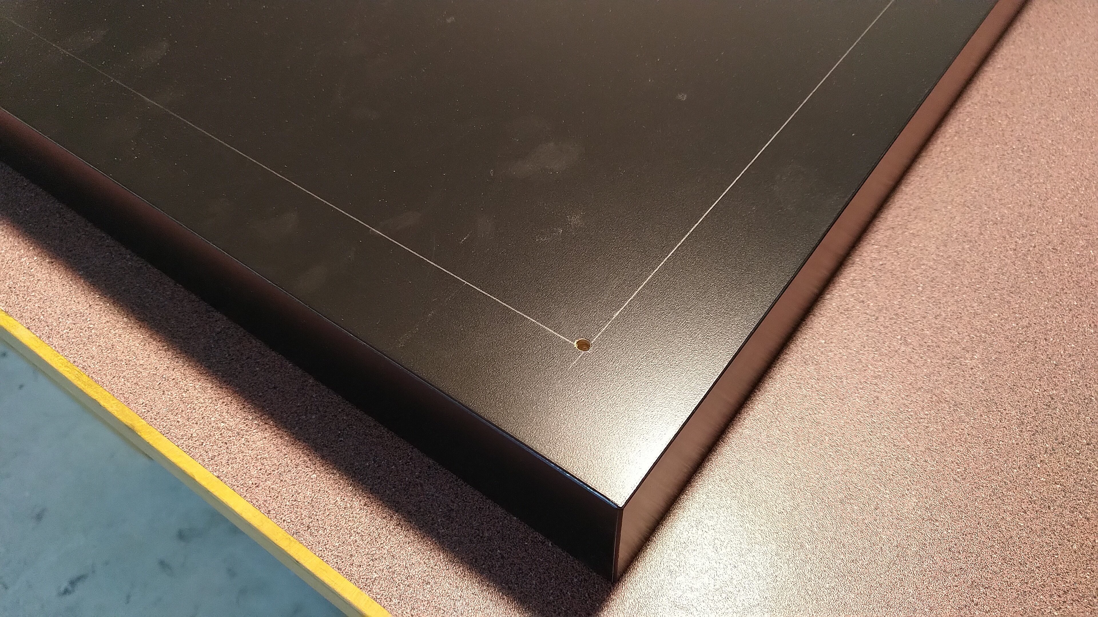
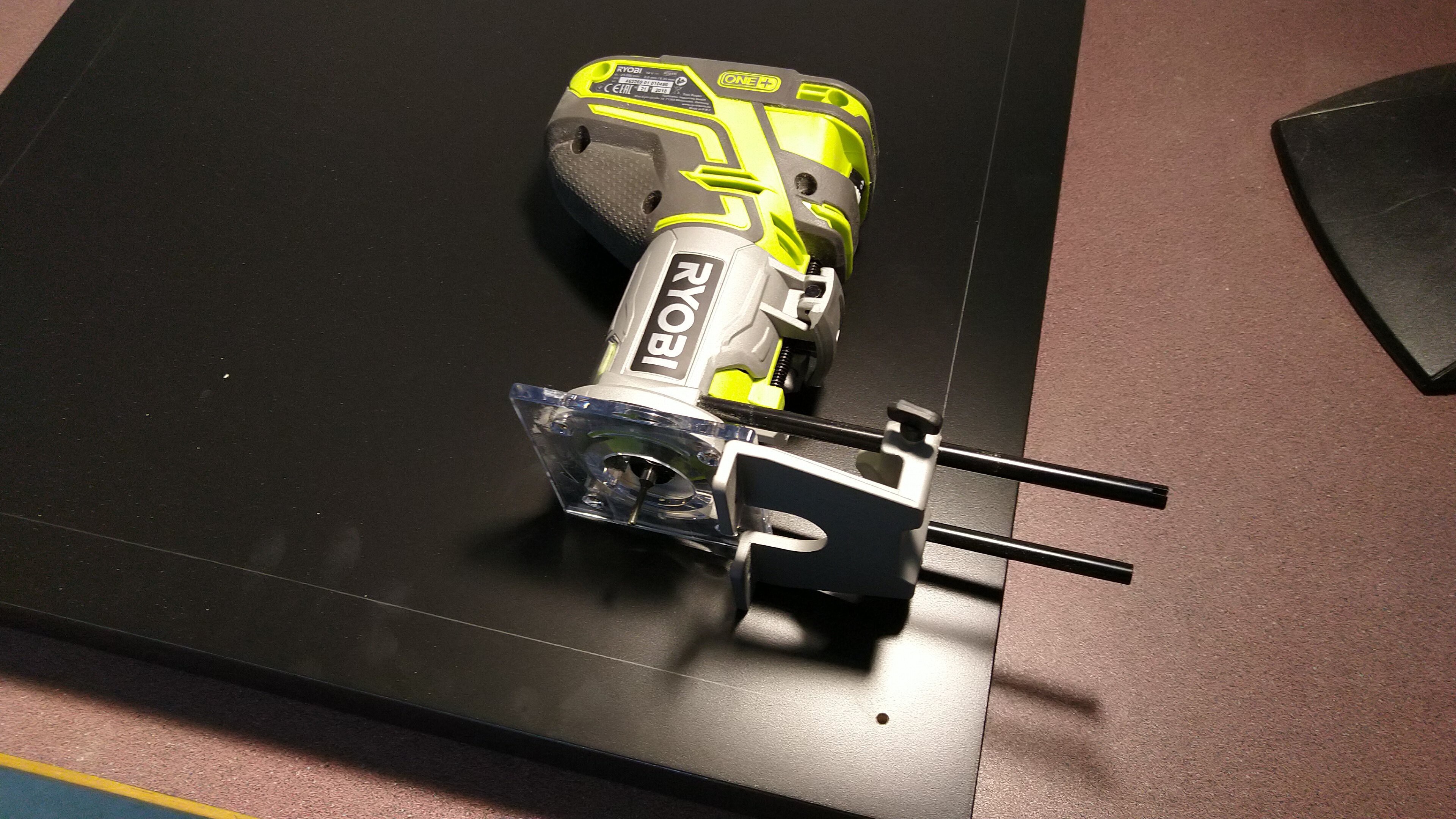
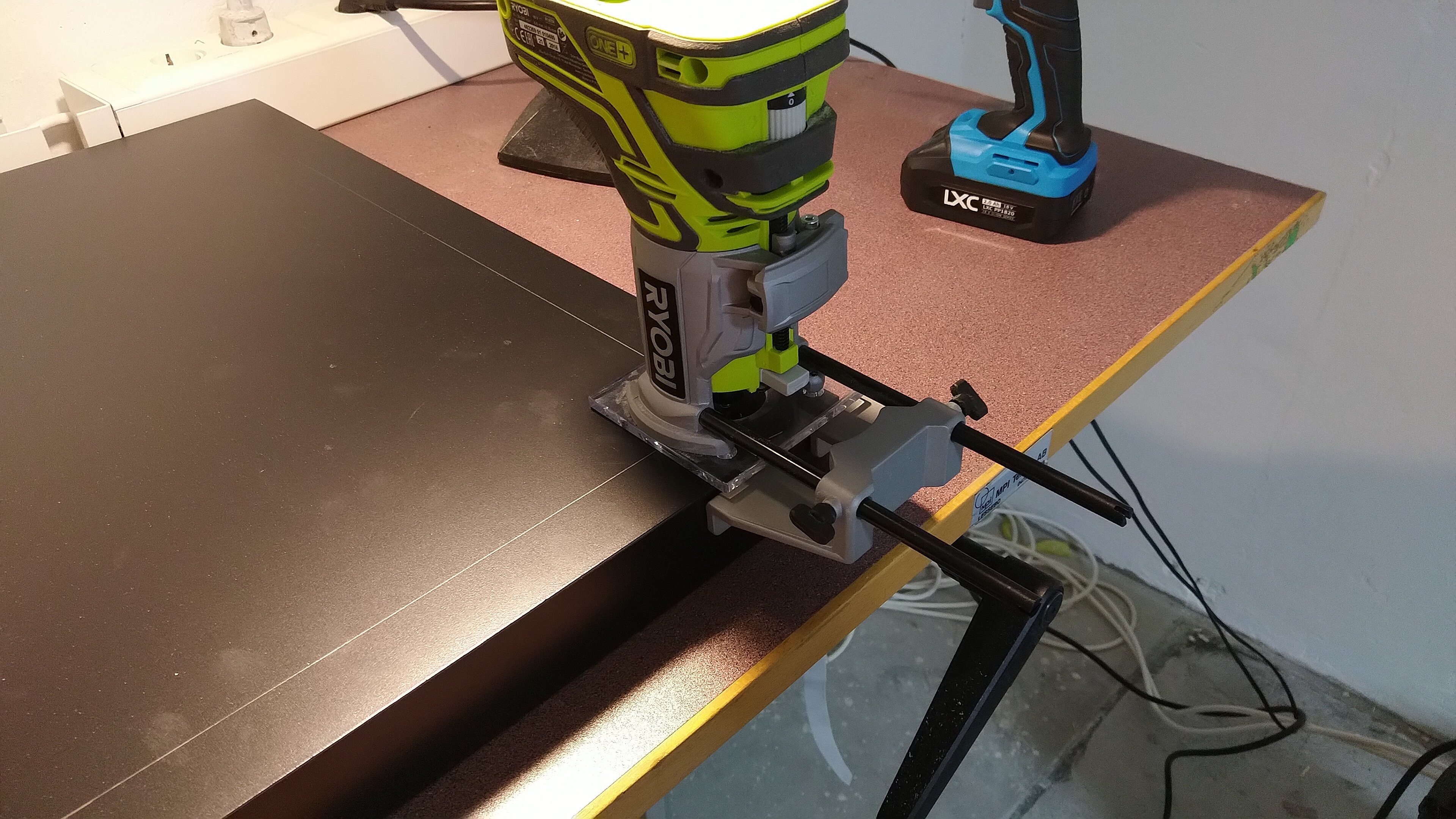
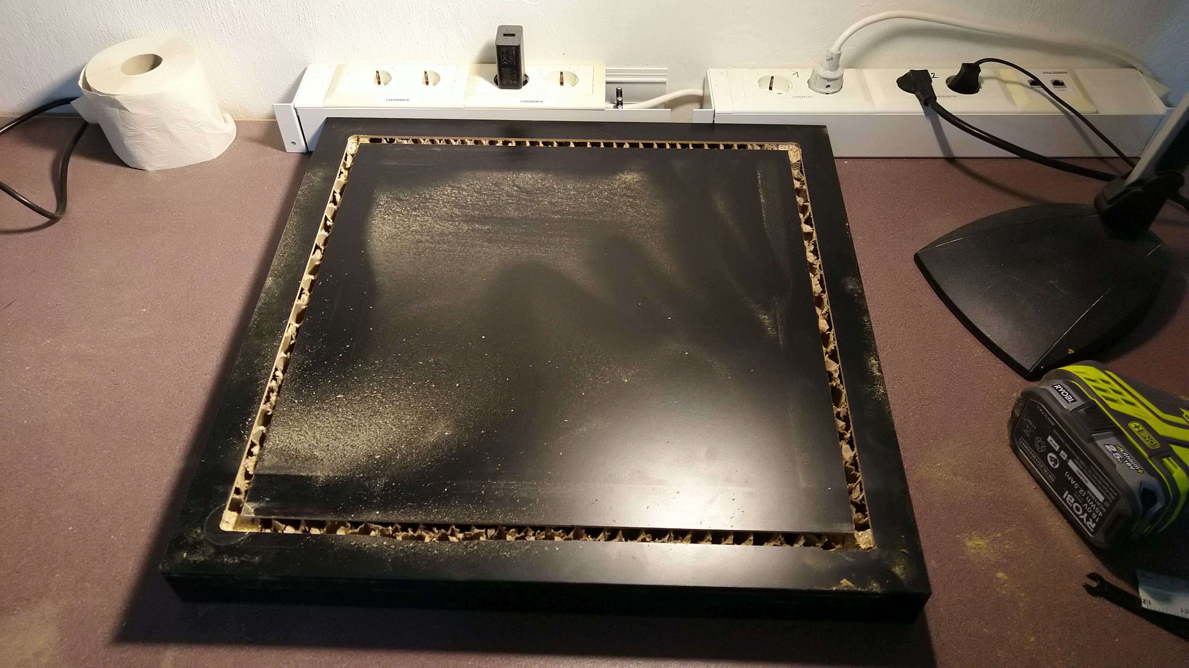
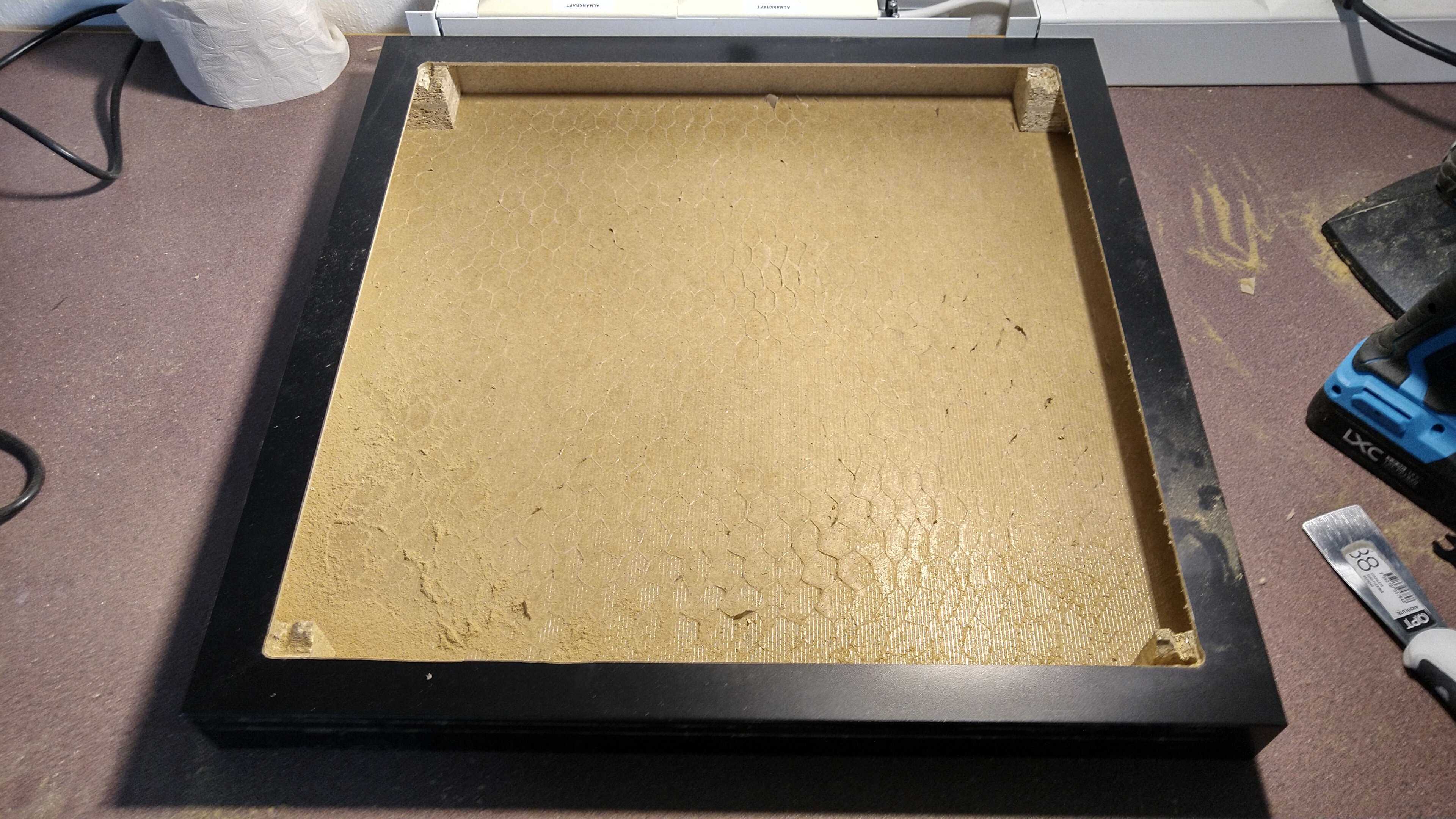
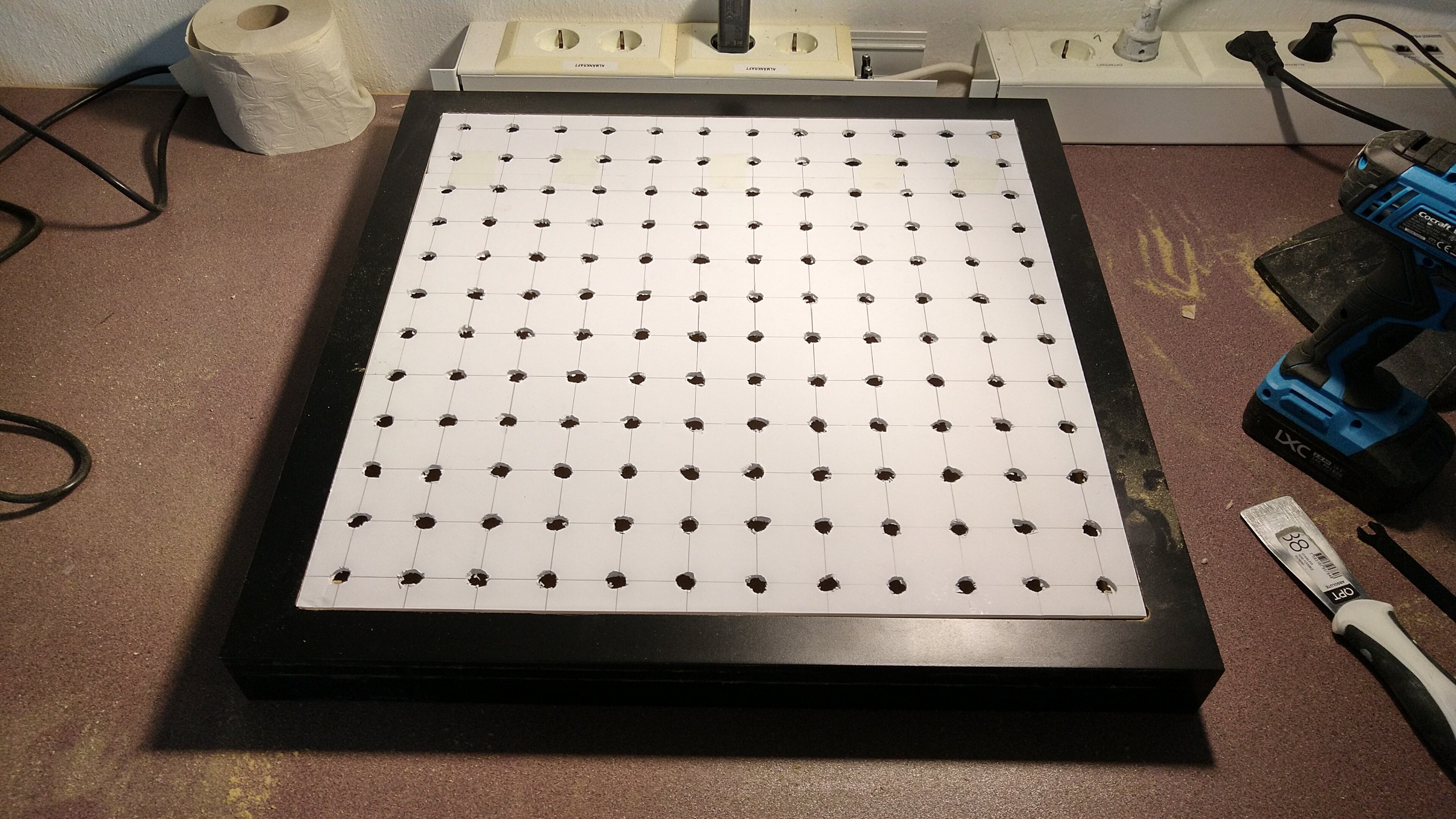
Lack Ping Pong LED Matrix
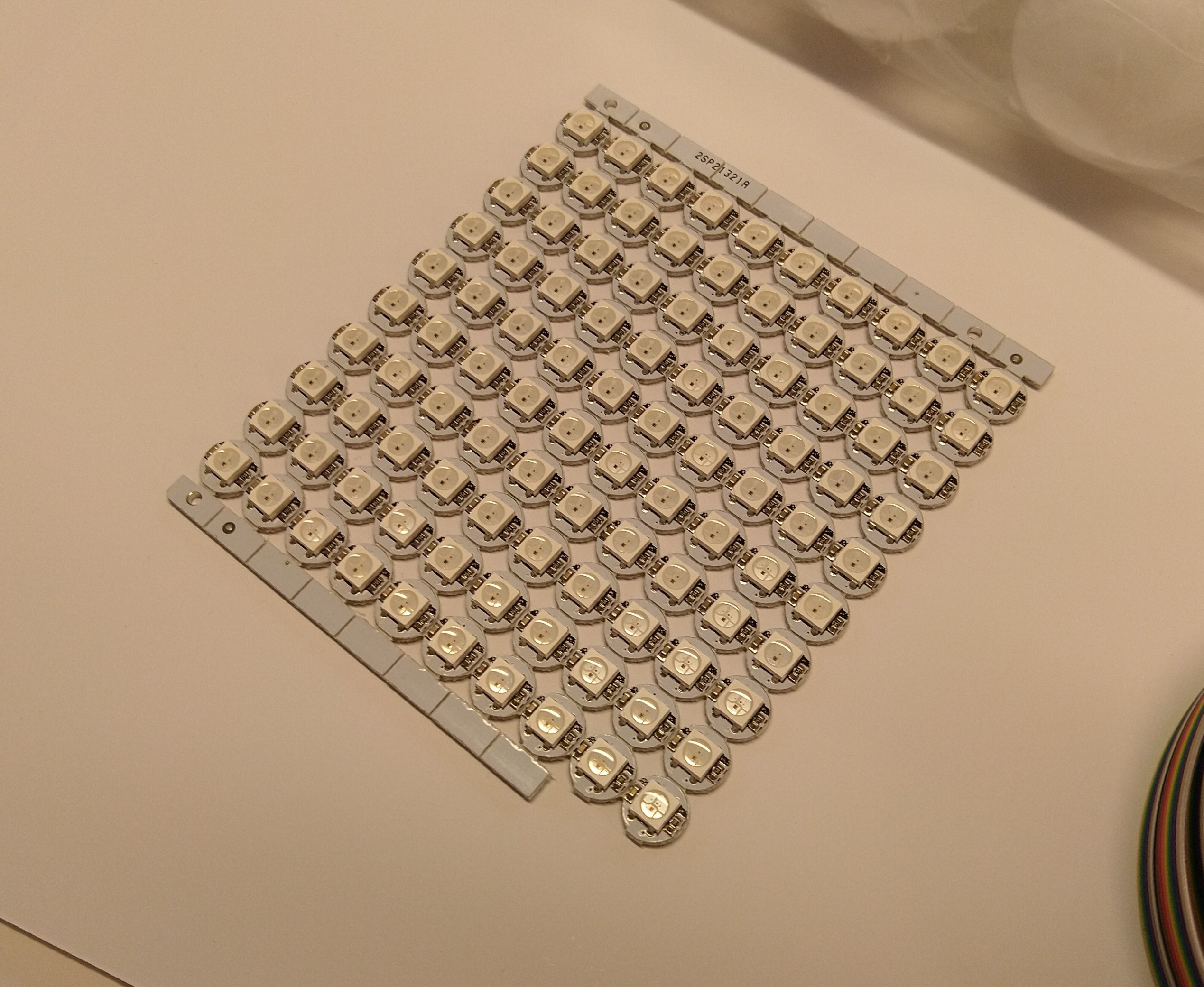
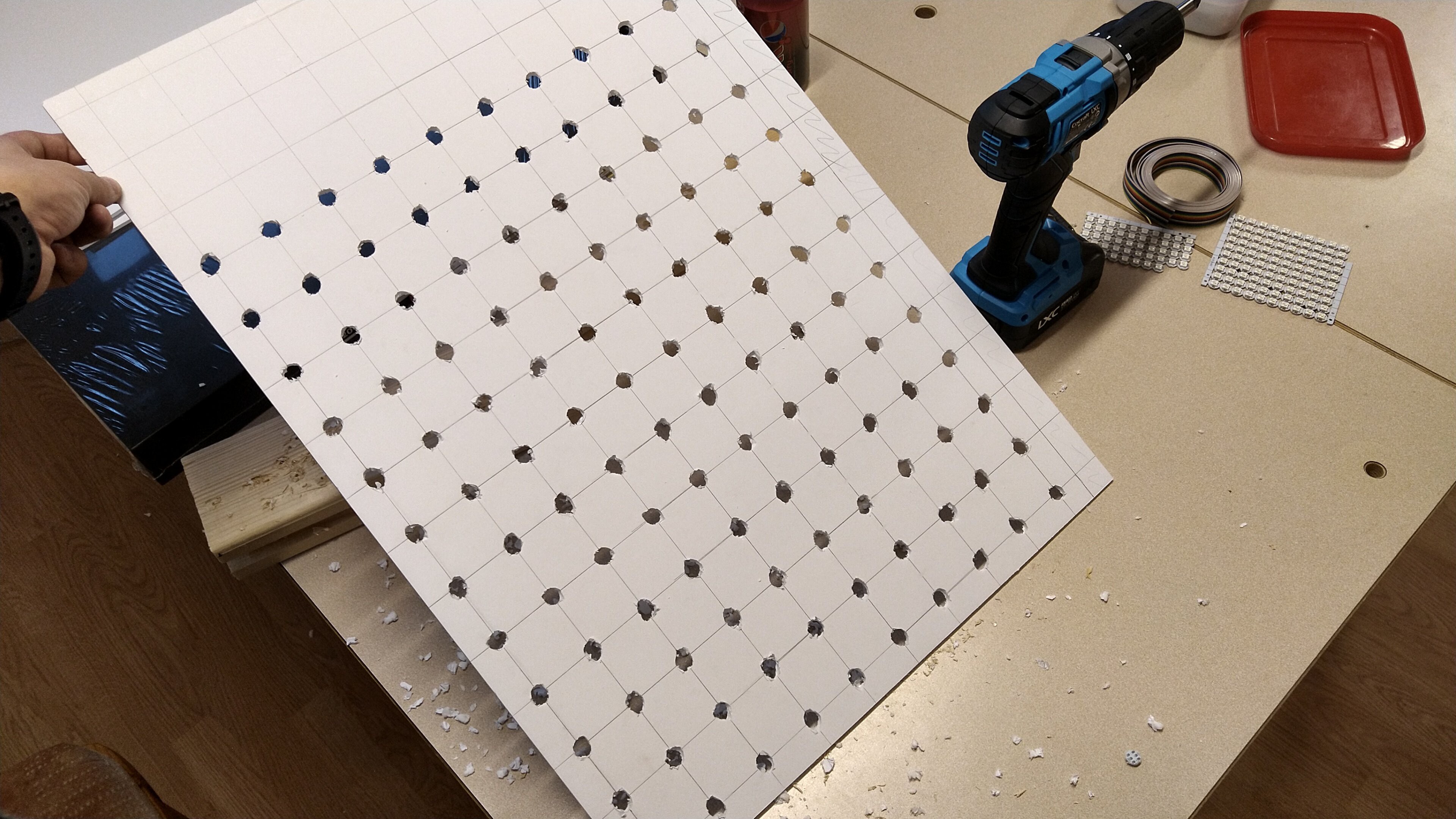
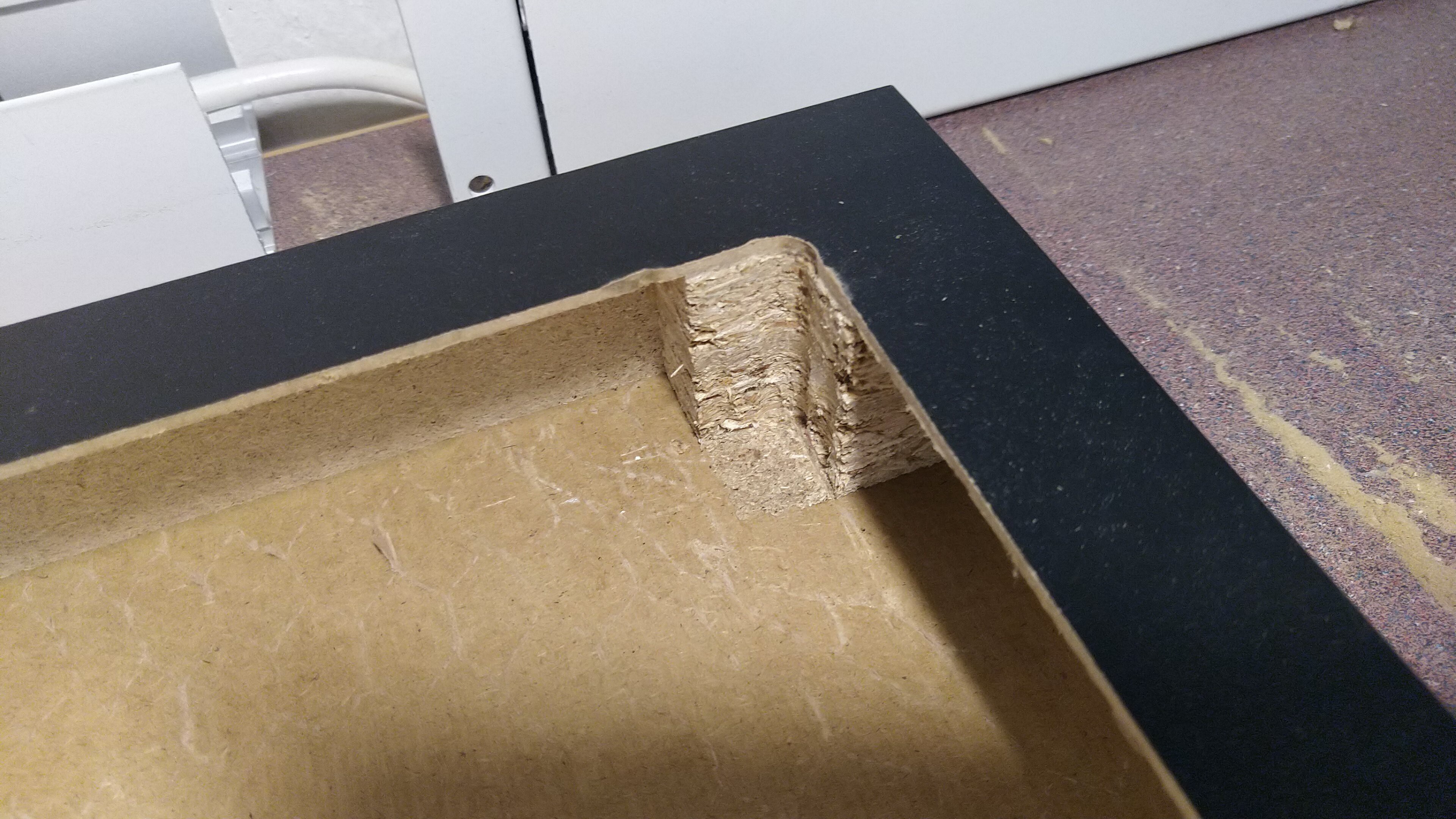
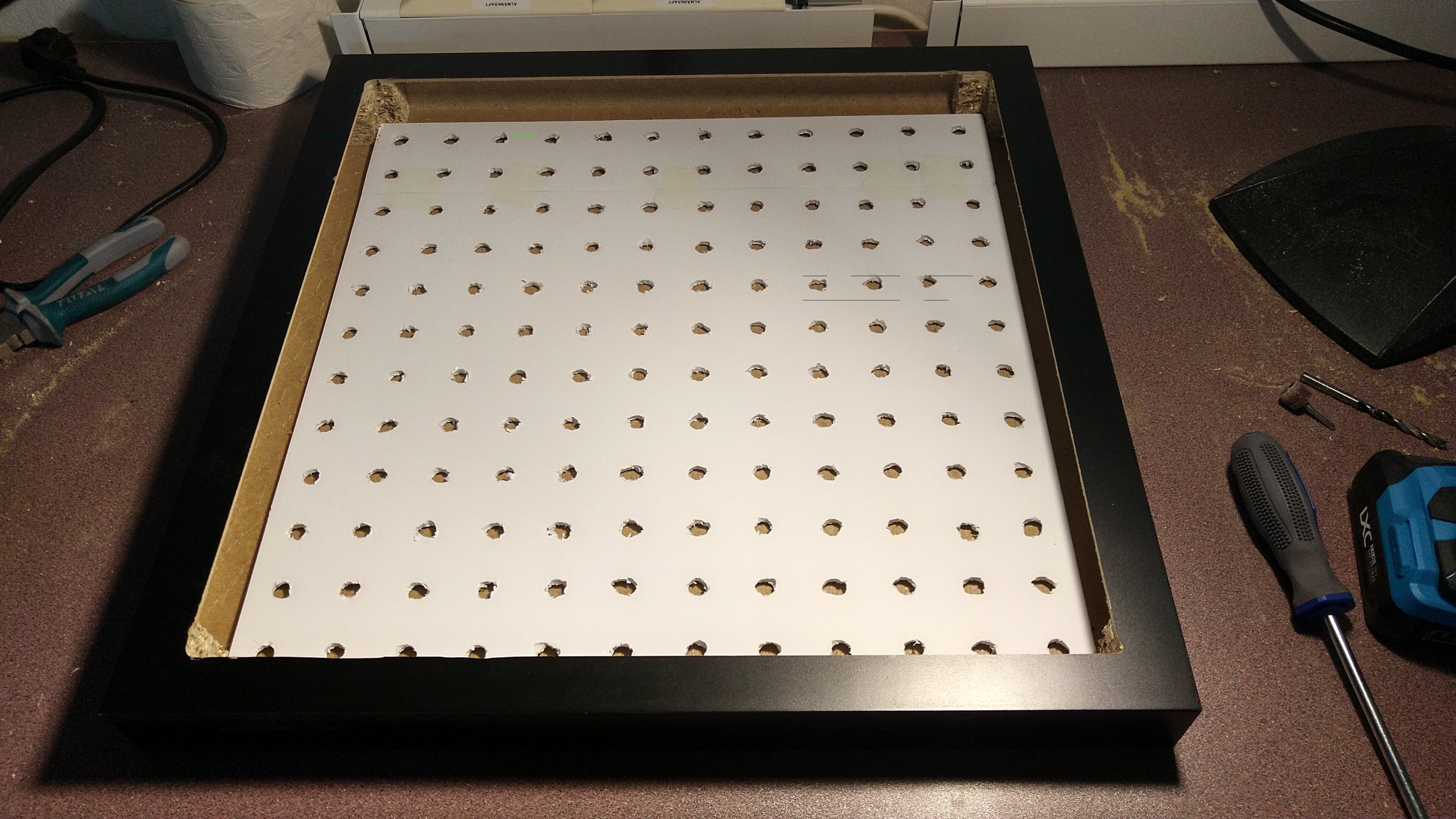
A 12x12 LED Matrix with Ping Pong ball diffusion, framed in a Ikea Lack table.
 arturo182
Become a Hackaday.io member
Already have an account? Log in.
Just one more thing
To make the experience fit your profile, pick a username and tell us what interests you.
Pick an awesome username
hackaday.io/
Your profile's URL: hackaday.io/username. Max 25 alphanumeric characters.
Pick a few interests
Projects that share your interests
People that share your interests


 Quinn
Quinn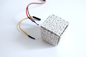
 deʃhipu
 Steve Pomeroy
 Morning.Star
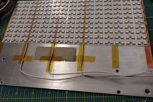
We also created this table just without the ikea table. We used a ESP Zero