 arturo182
I've been wanting to create a LED Matrix of some kind for some time now, I even tried before with a laser cutter and a lack table, but it didn't turn out as well as I was hoping. Then I saw a project on /r/DIY that was using ping pong balls as LED diffusers and it clicked for me!
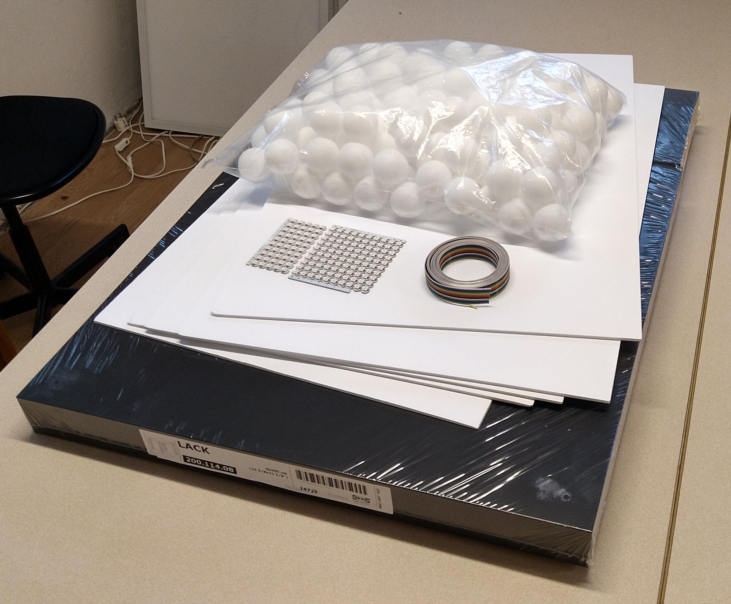
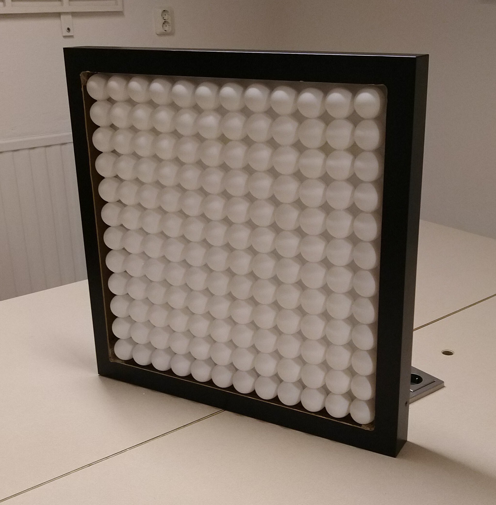
Since I used a Lack table before and I live in Sweden (yay Ikea), it seemed fitting to use it again. The table is 55x55 cm and the balls are 4 cm in diameter, meaning I could make a 12x12 LED matrix easily. I was also using foam board as scaffolding for the matrix. For LEDs, I used a panel of fairly cheap and very popular WS2812b, they can be easily driven with a Raspberry Pi and the Satanic/Sexy/Stupid/Silly/Shiny LED matrix controller library.
Let's get to the build!
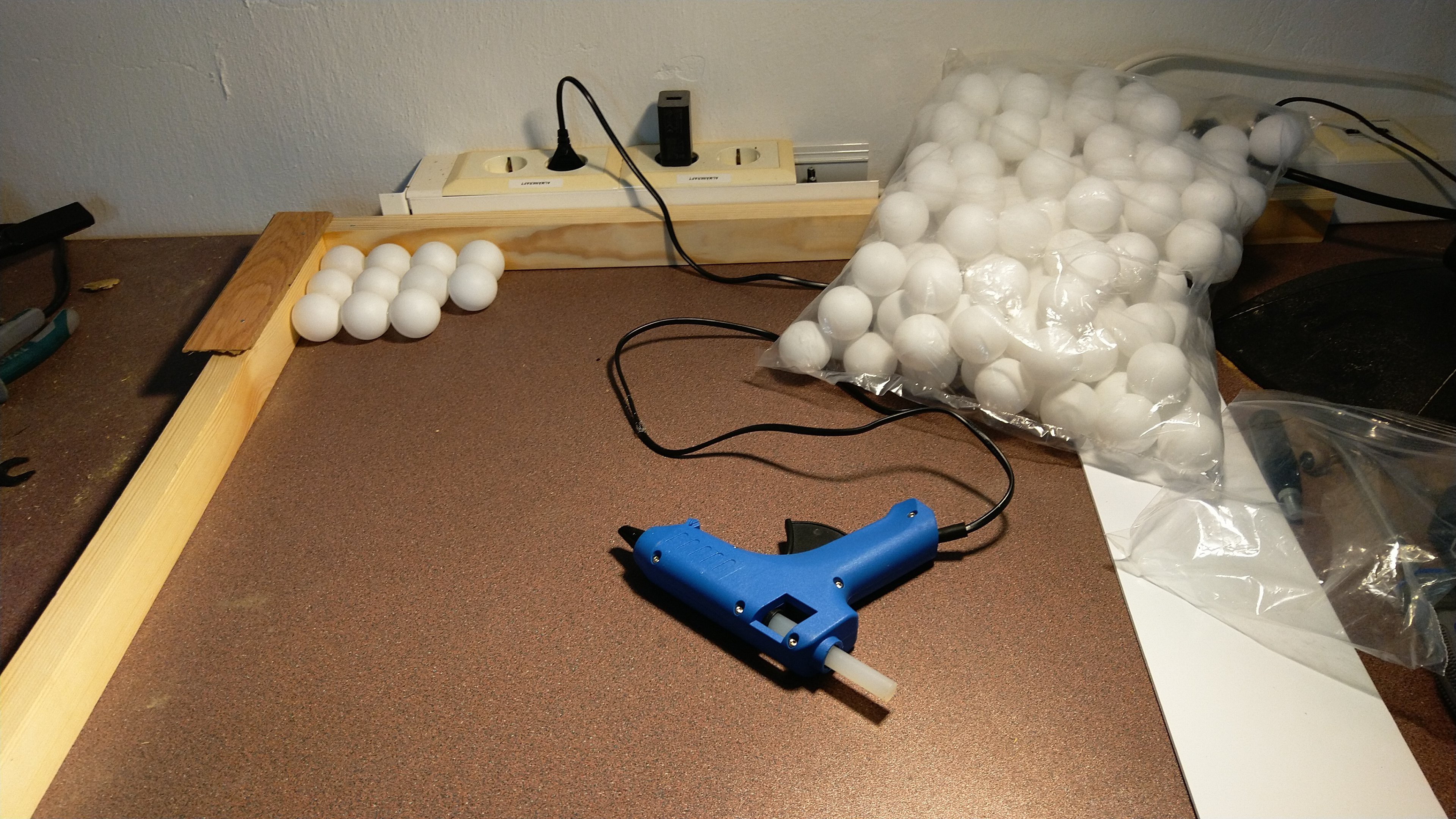
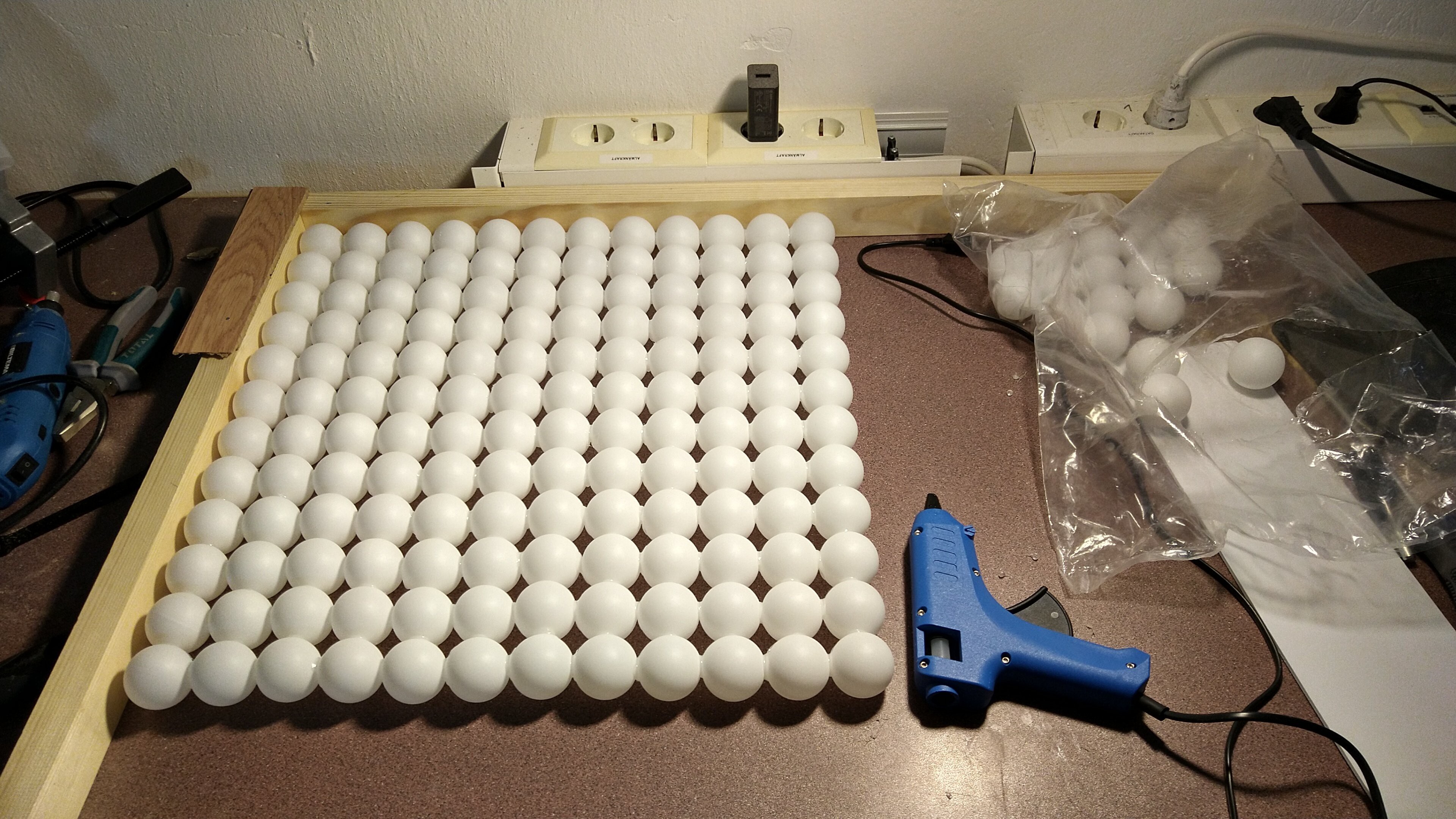
Here's most of the materials needed:
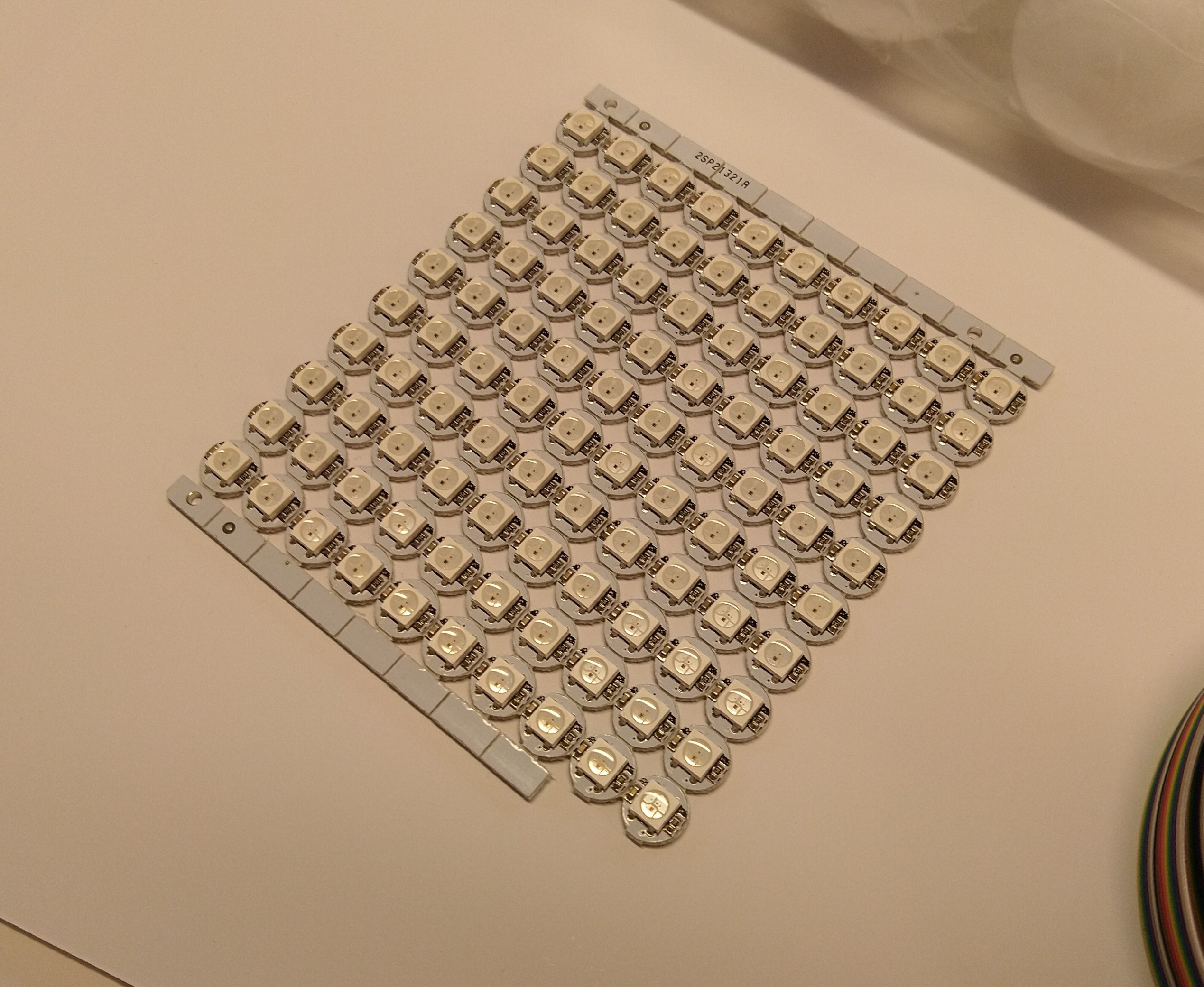
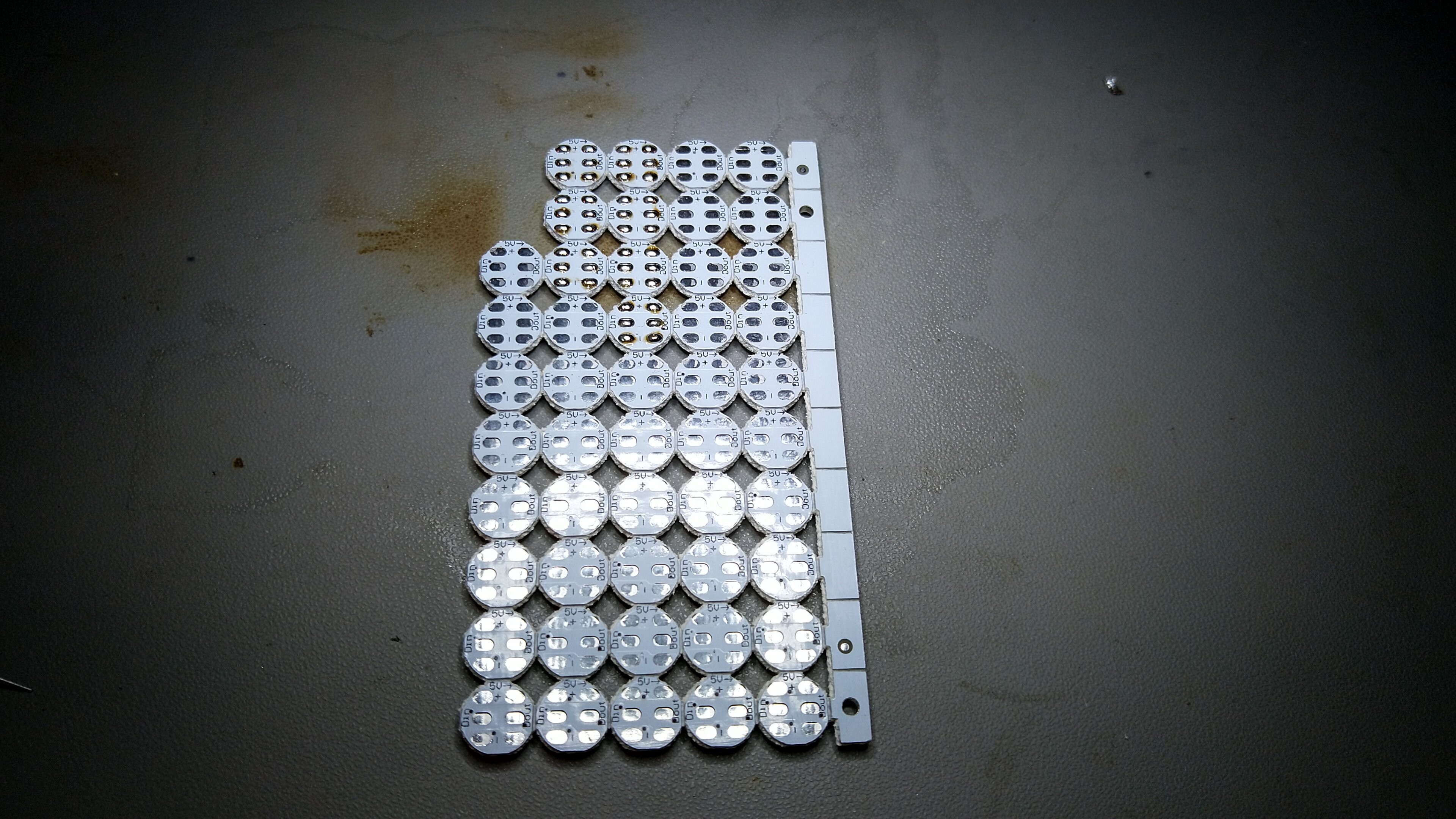
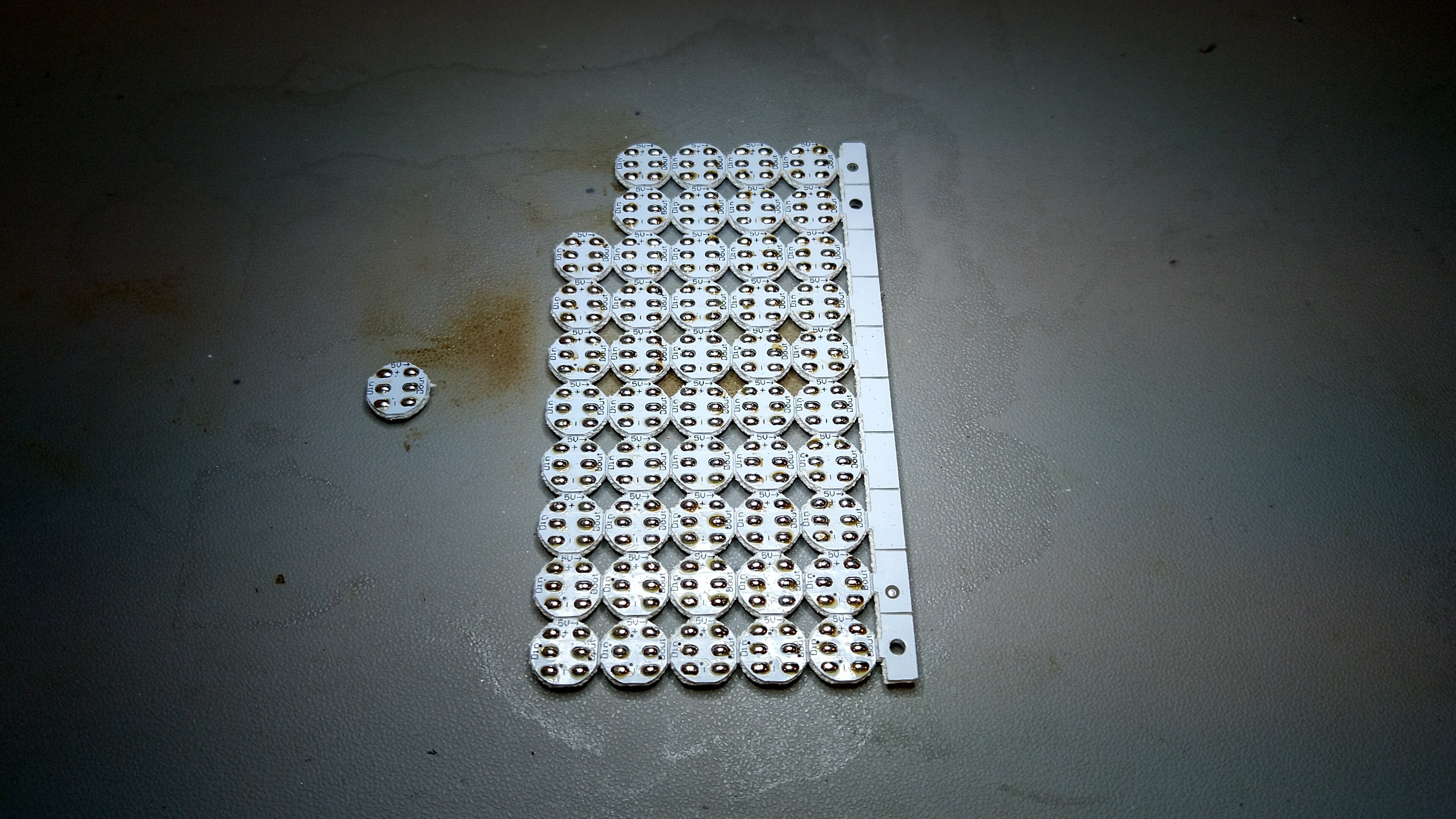
As mentioned, the LEDs come in a PCB panel where you can snap off each PCB easily. Having them initially in a panel made the soldering easier.
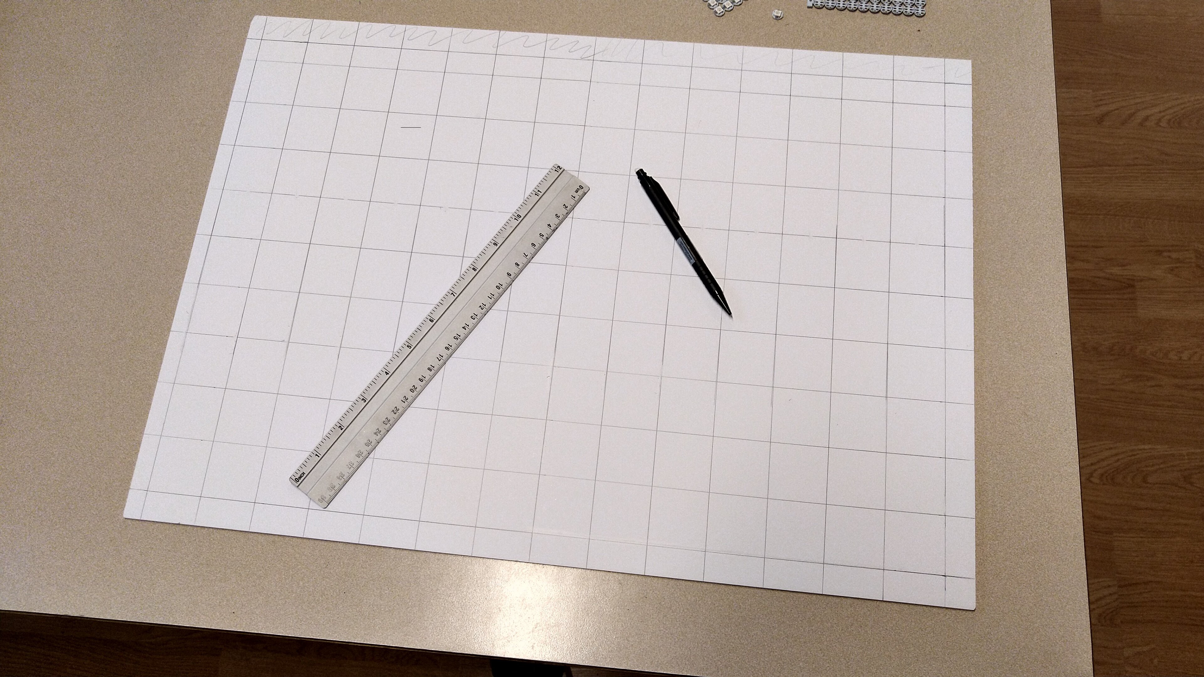
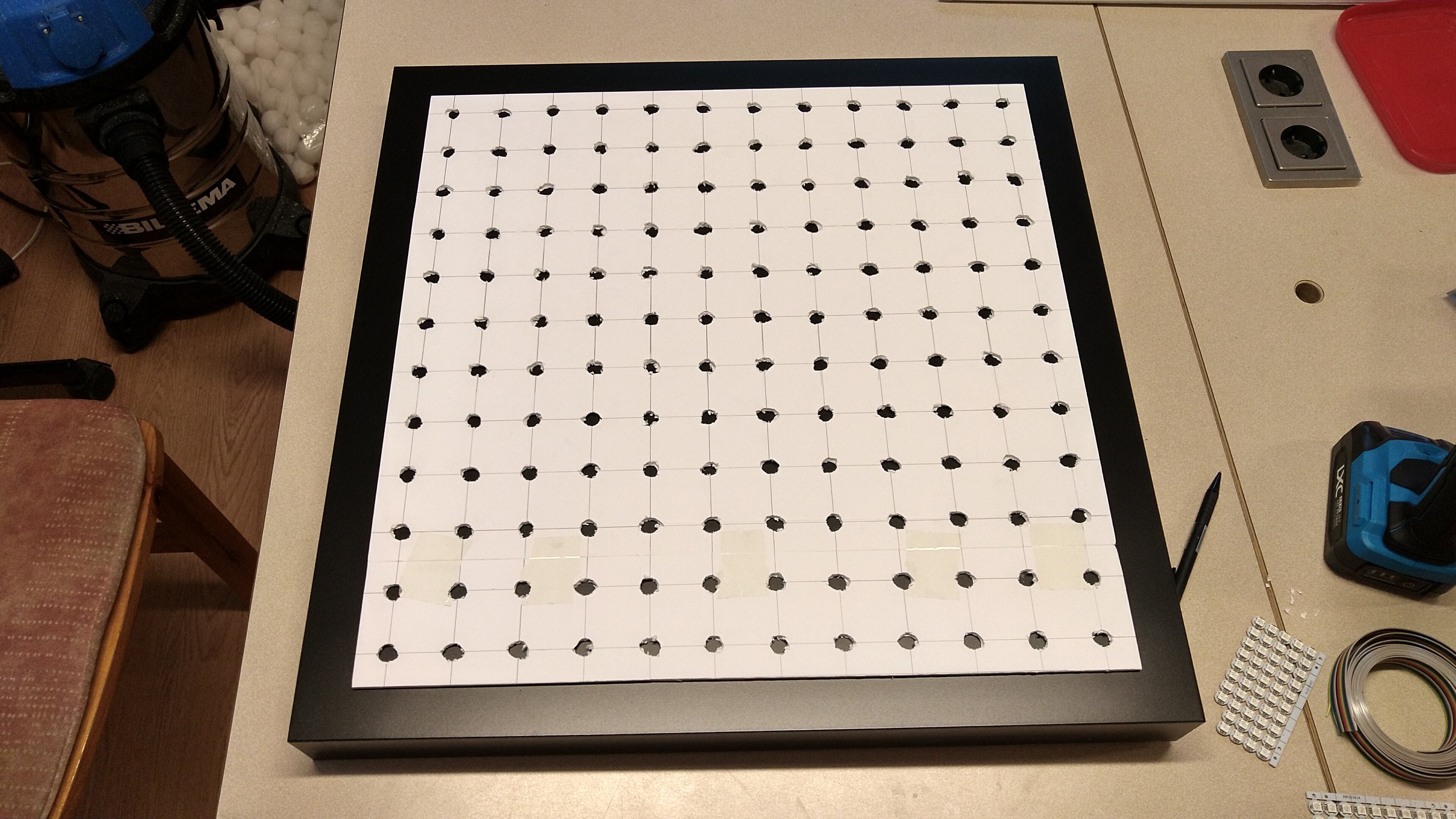
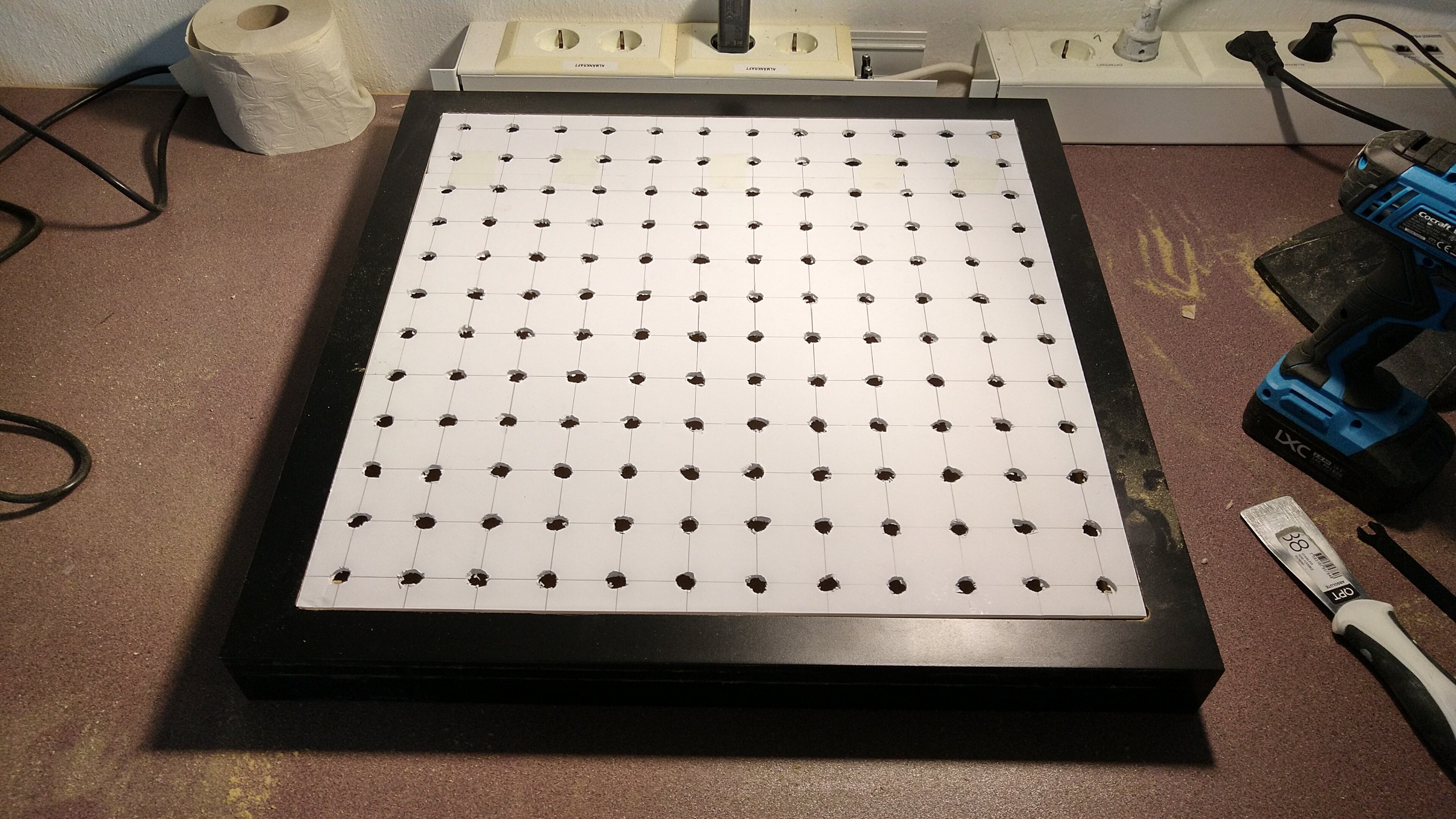
I started with drawing a 4cm x 4cm grid on the foam board, this is where each ball would go.
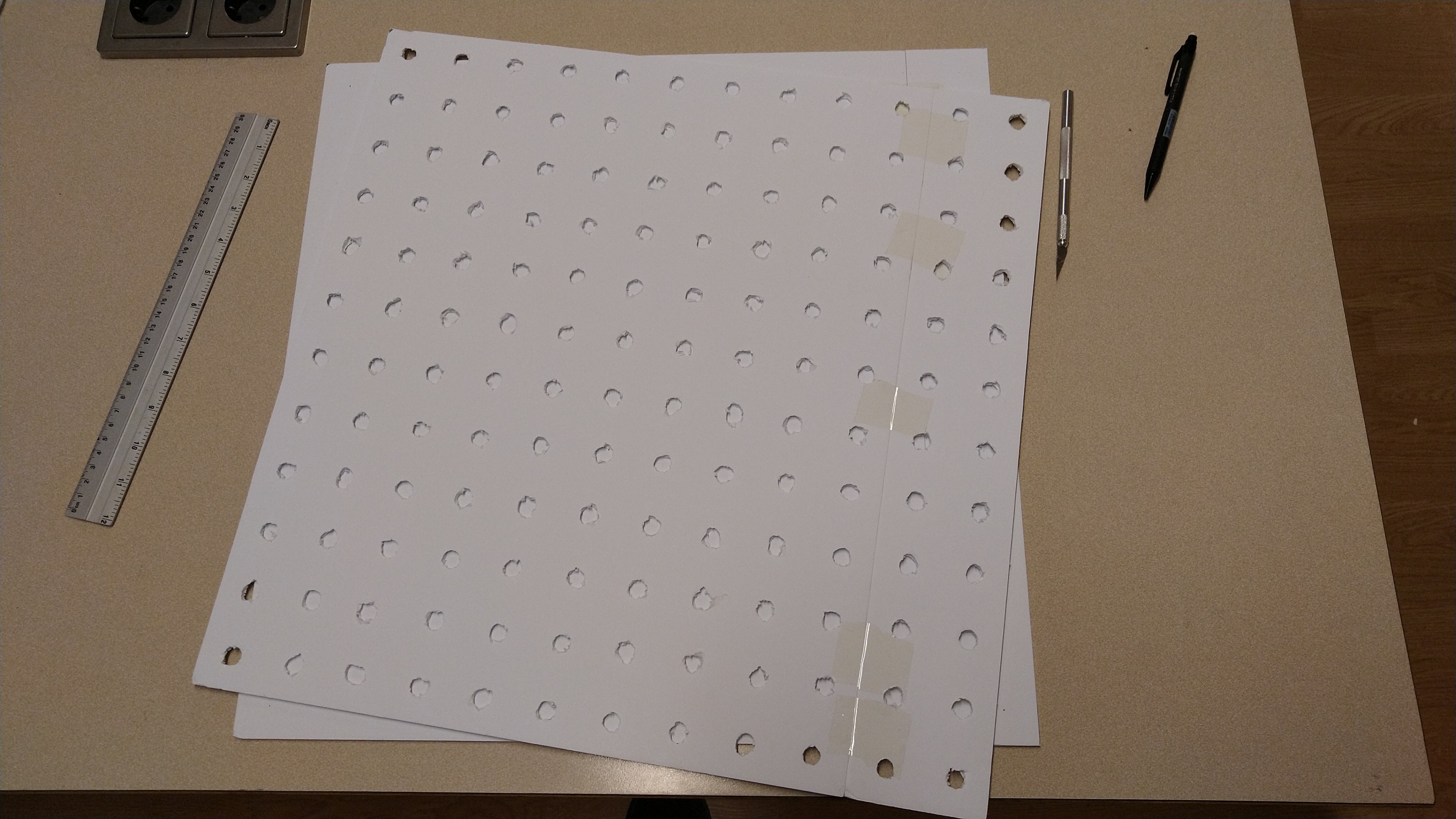
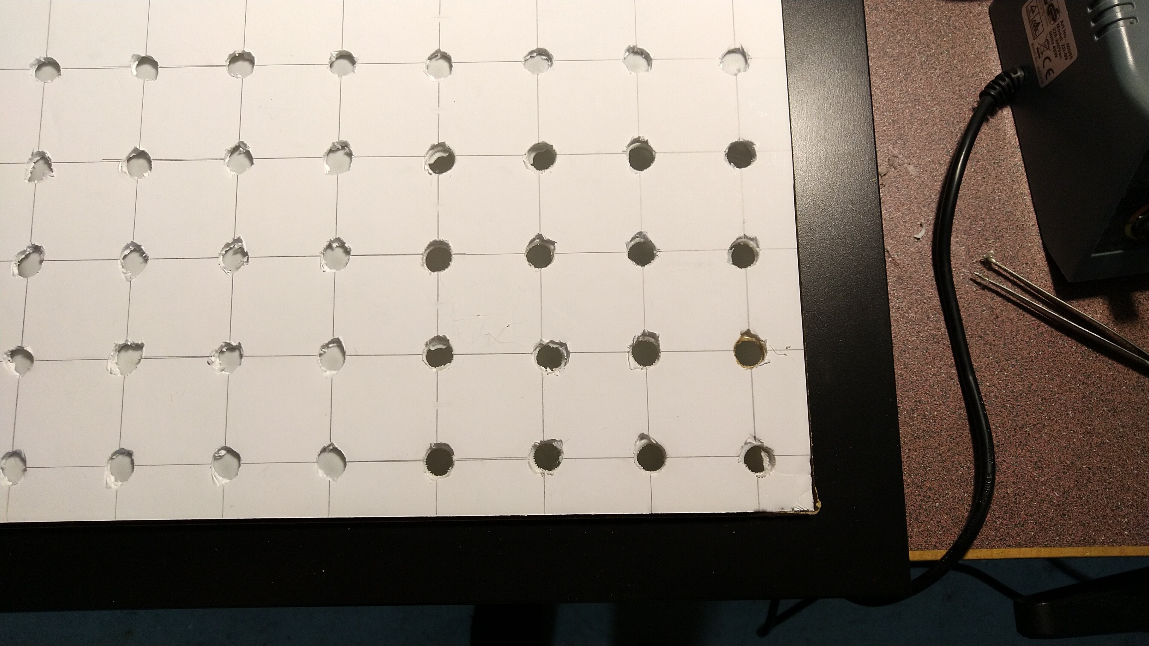
Since I wanted to have the matrix not glued together as one piece but as two separate ones, I needed holes in the foam that would hold the ping pong balls so the LEDs could shine through. Enter the drill:
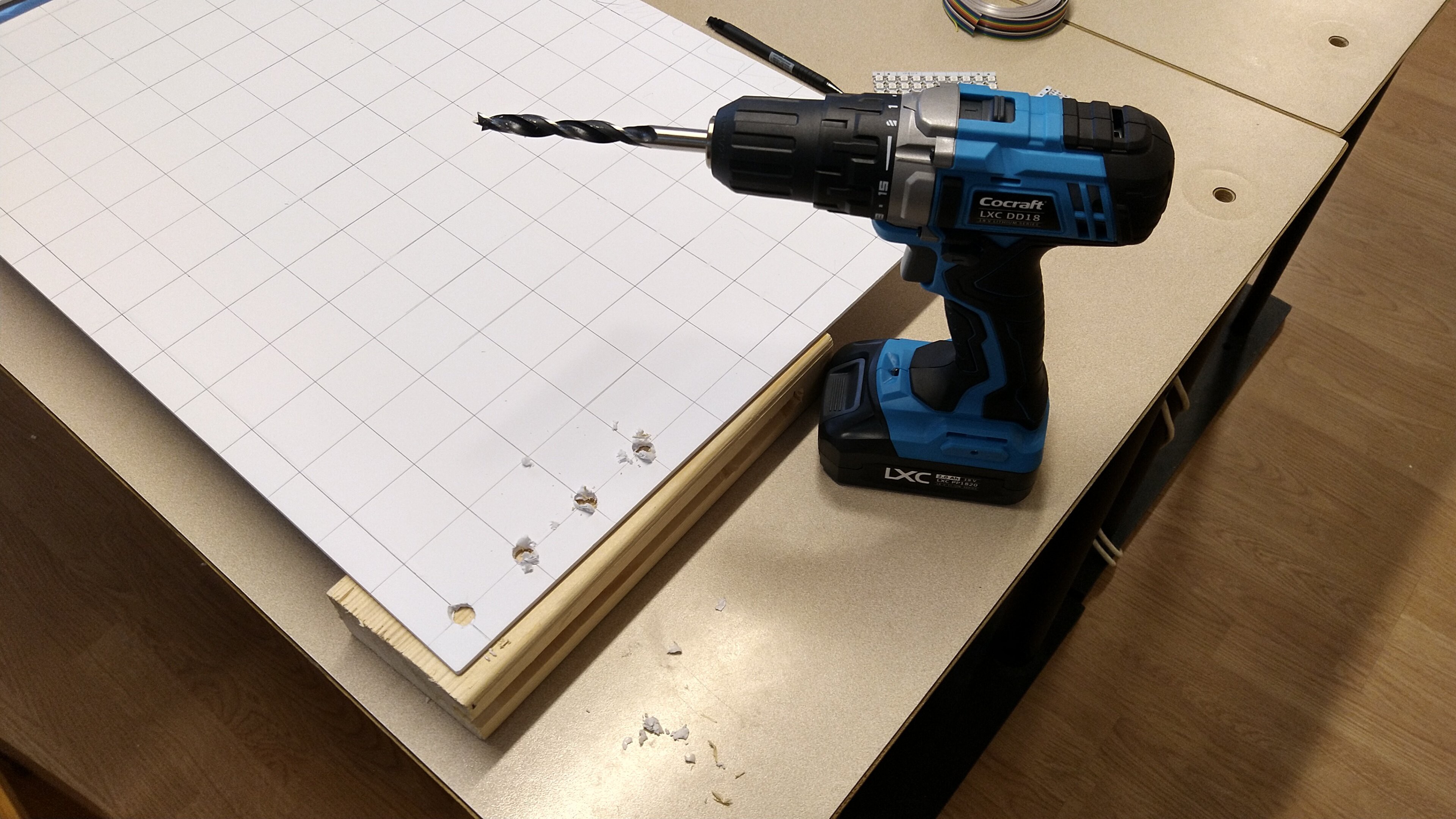
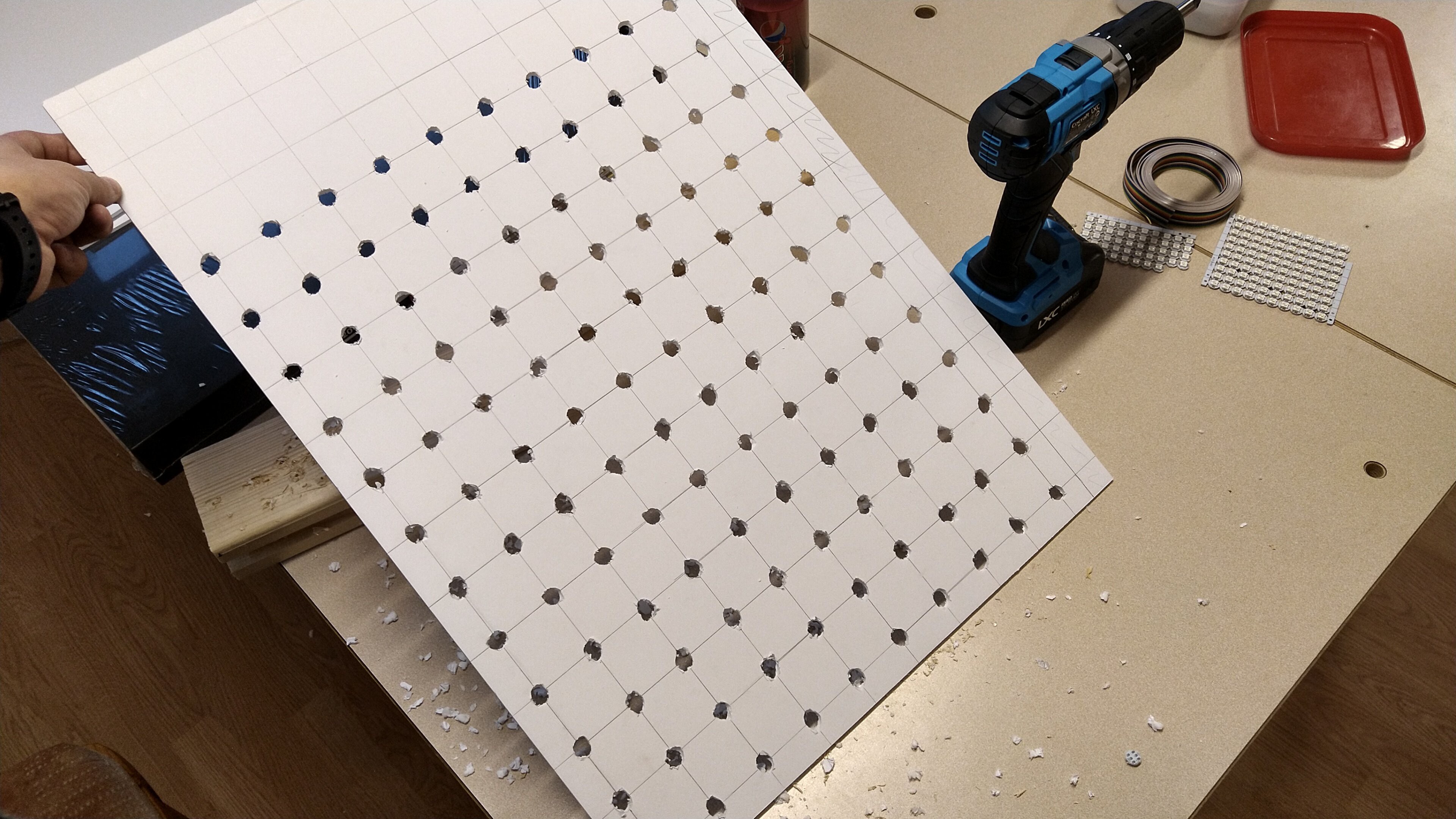
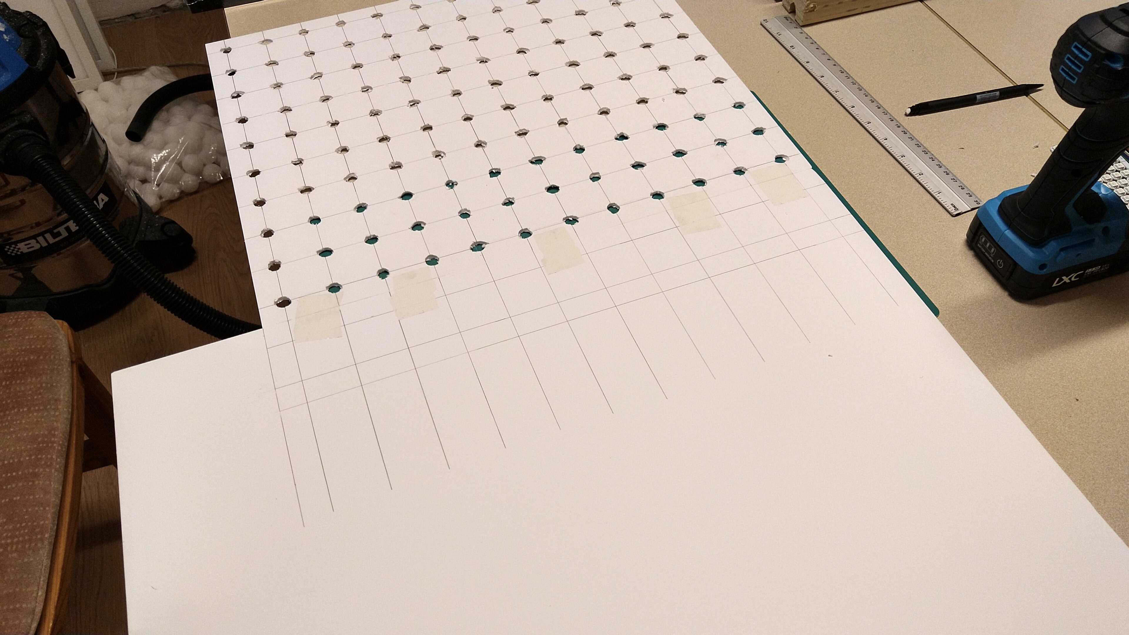
The foam board used as A2-sized, which was not large enough for the 12x12 matrix, so I simply taped another board to it, extended the grid and drilled the rest of the holes. Note the vacuum in the back, the foam creates quite a mess so make sure to keep your workbench clean!
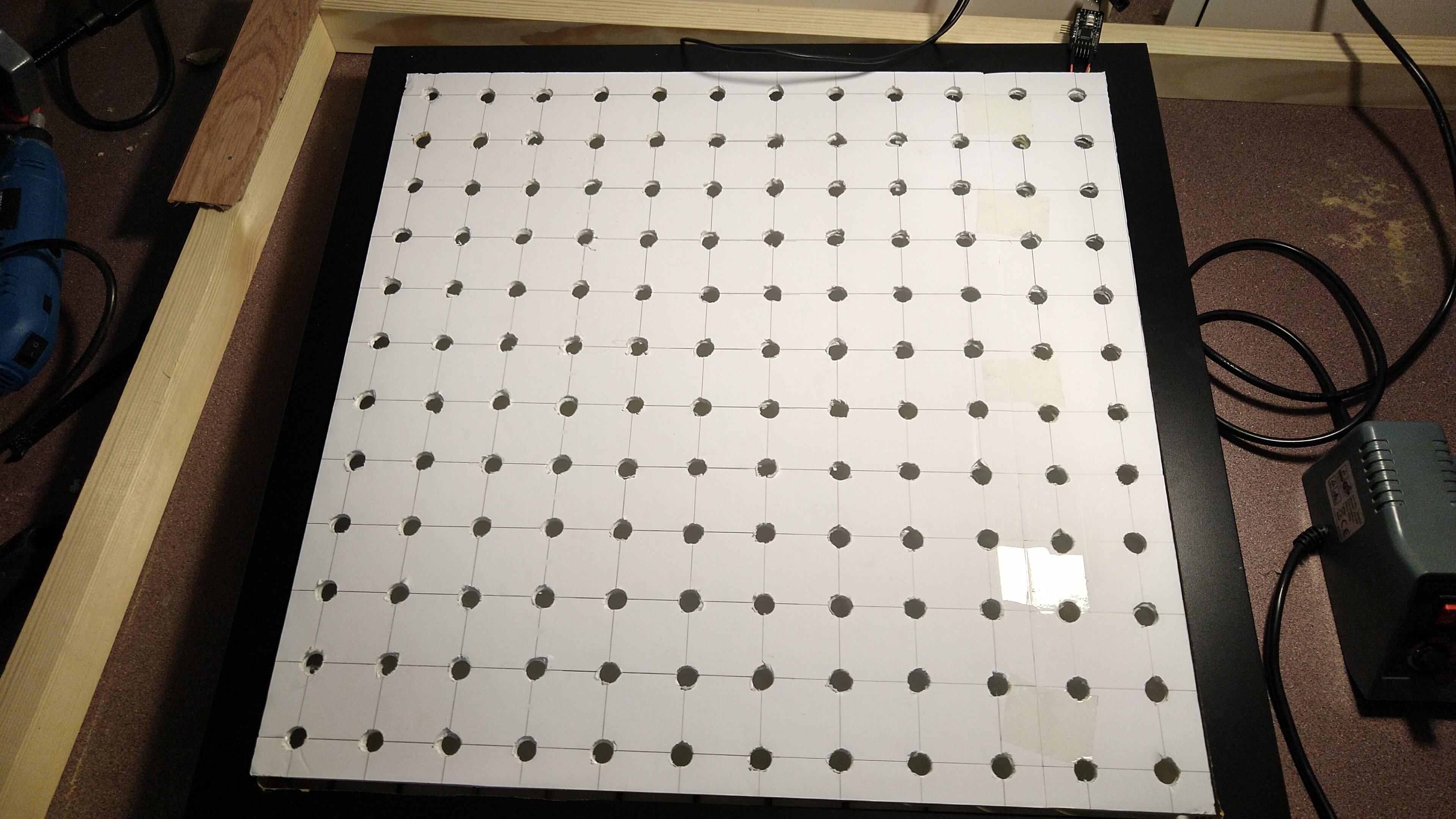
After I was done with that part, I cut the foam to size and I had my ball scaffolding!
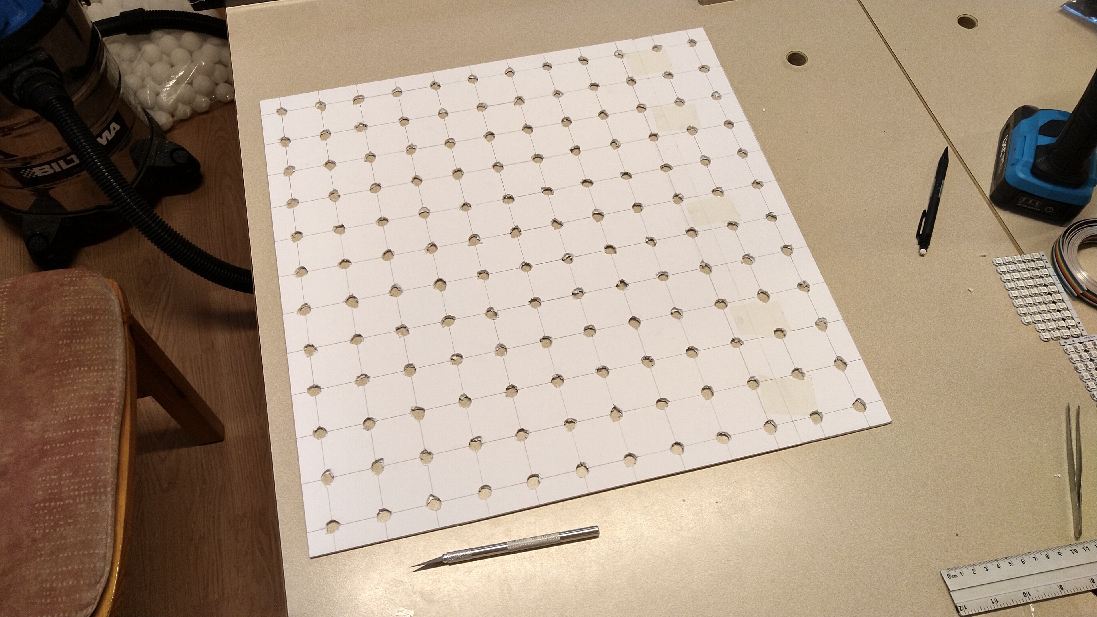
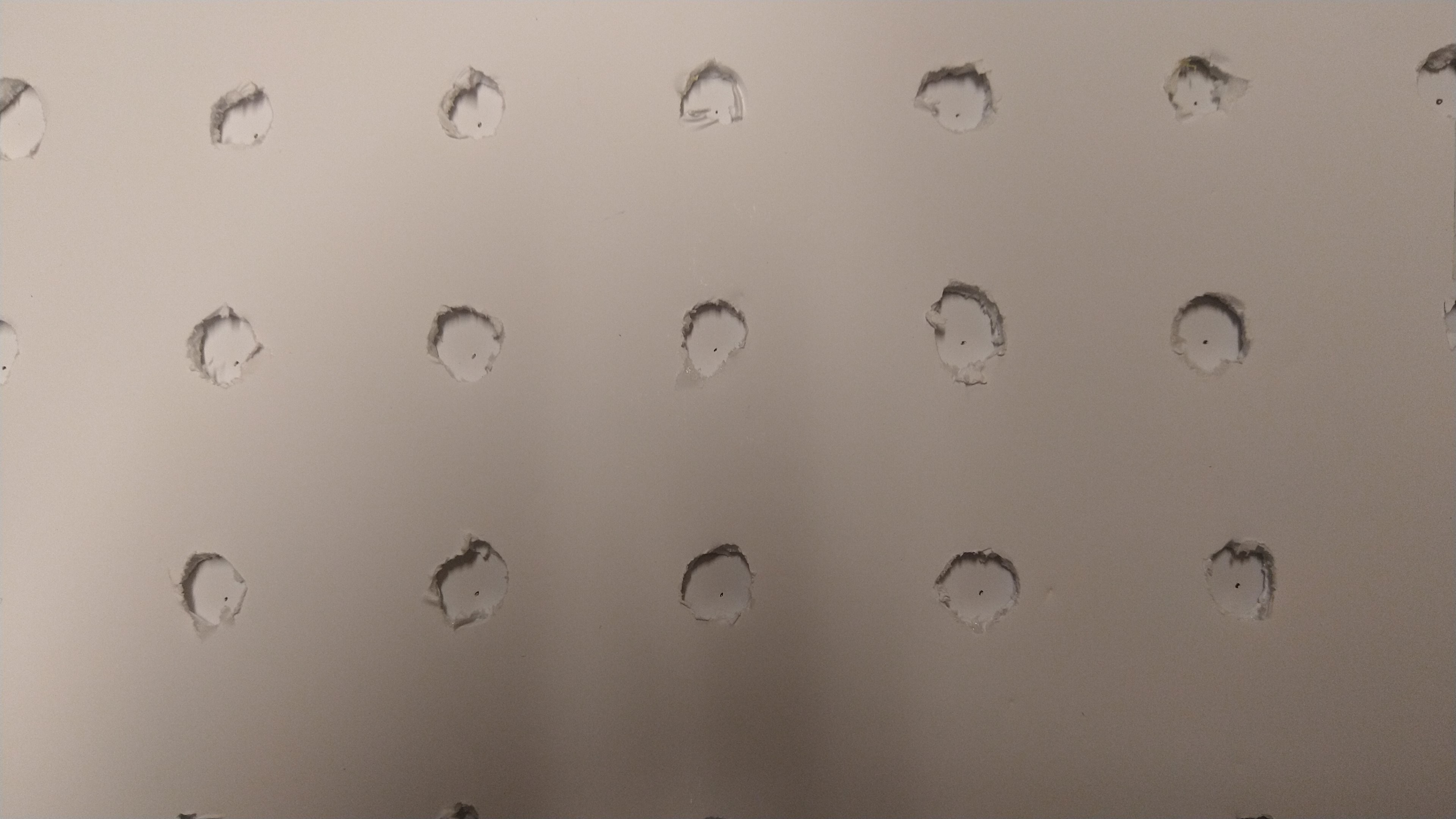
I used a 10mm drill which was more than enough for the LEDs, one issue you might notice was that the foam didn't drill very cleanly, since it is just paper and foam. In hindsight, I would've used a hot soldering iron tip to burn the holes.
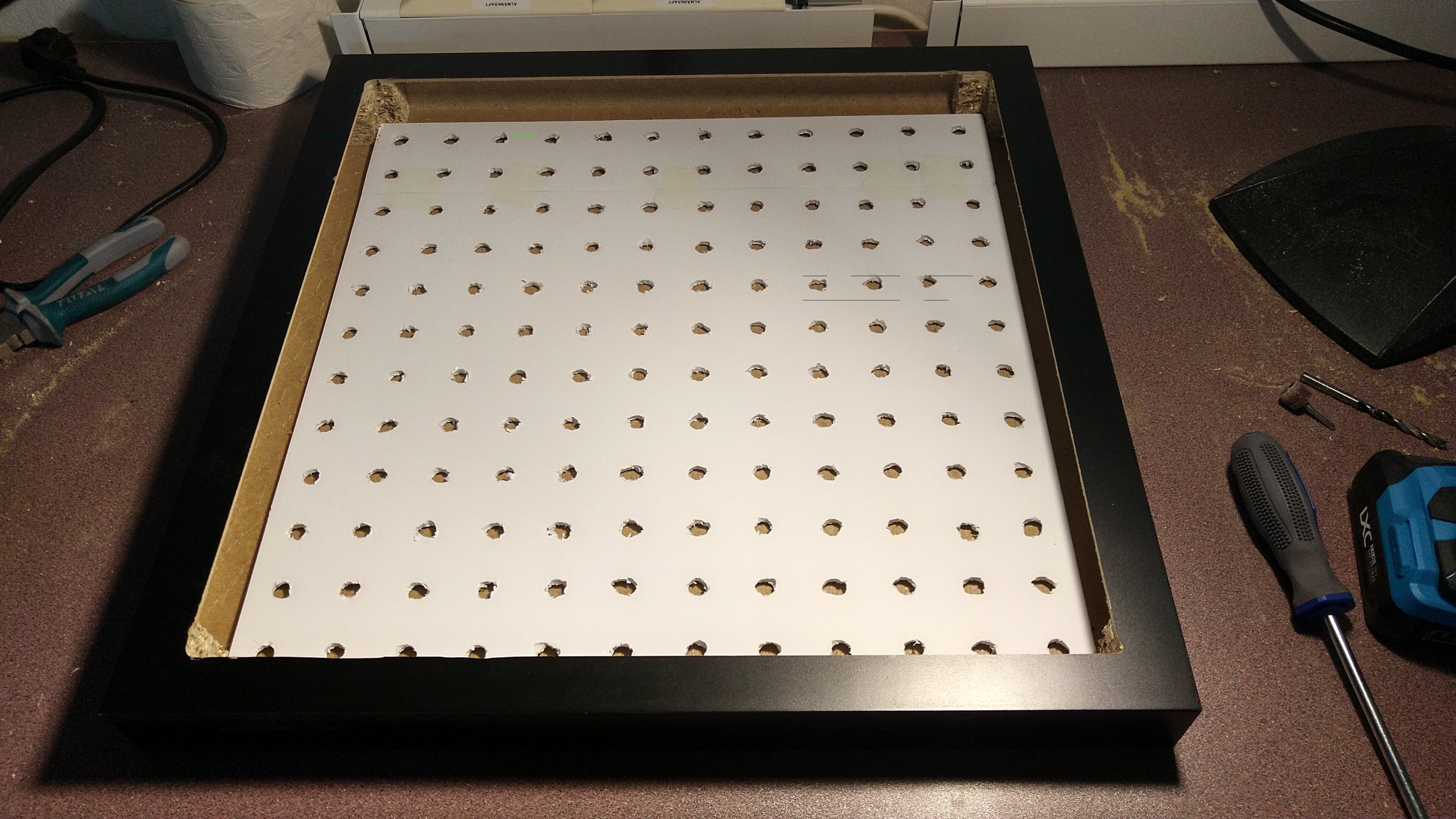
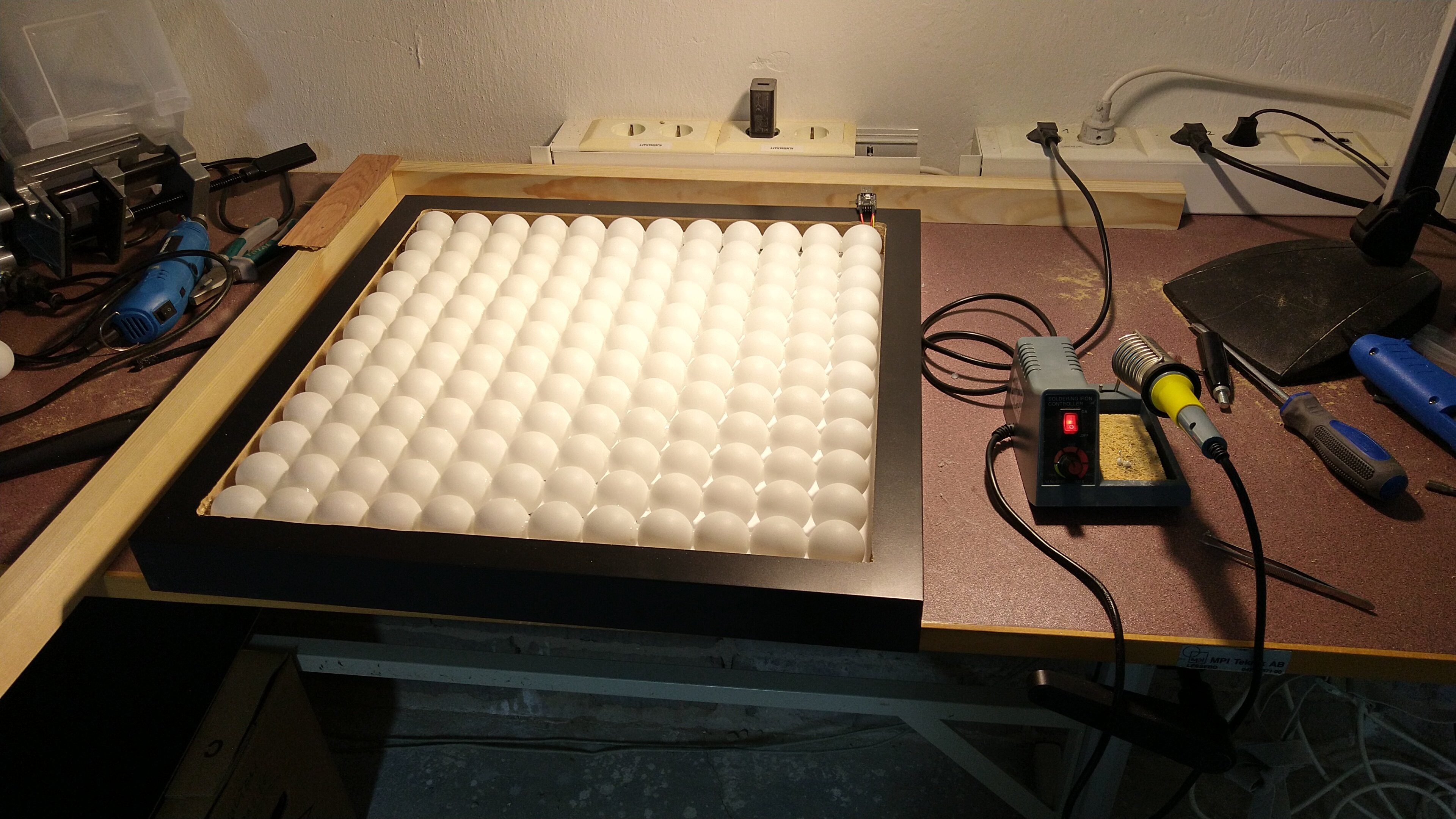
Quick fit-test on the Lack and looks good!
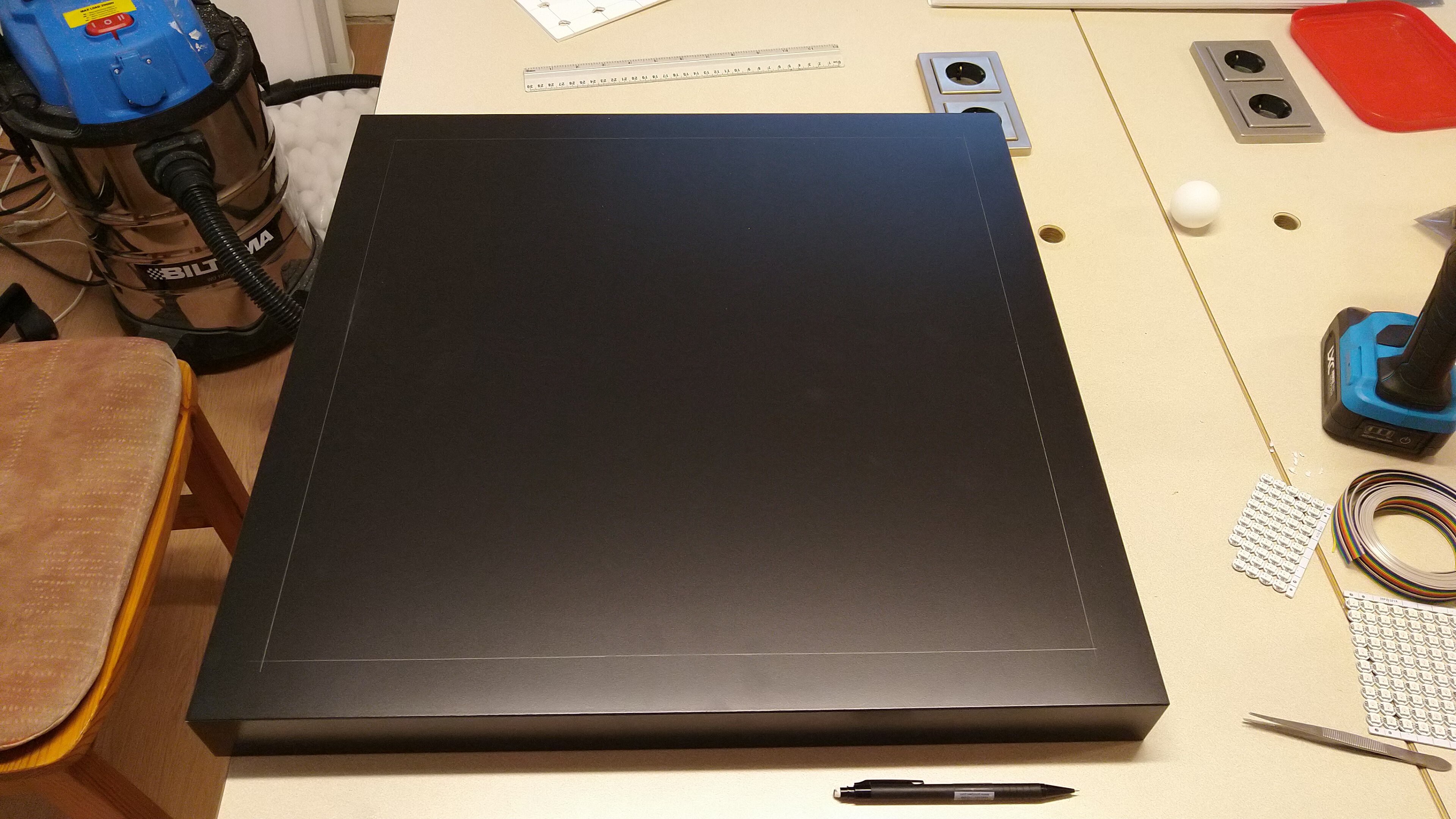
I then marked the Lack so I could route it. 12 x 4 cm = 48 cm, leaving us 3.5 cm each side.
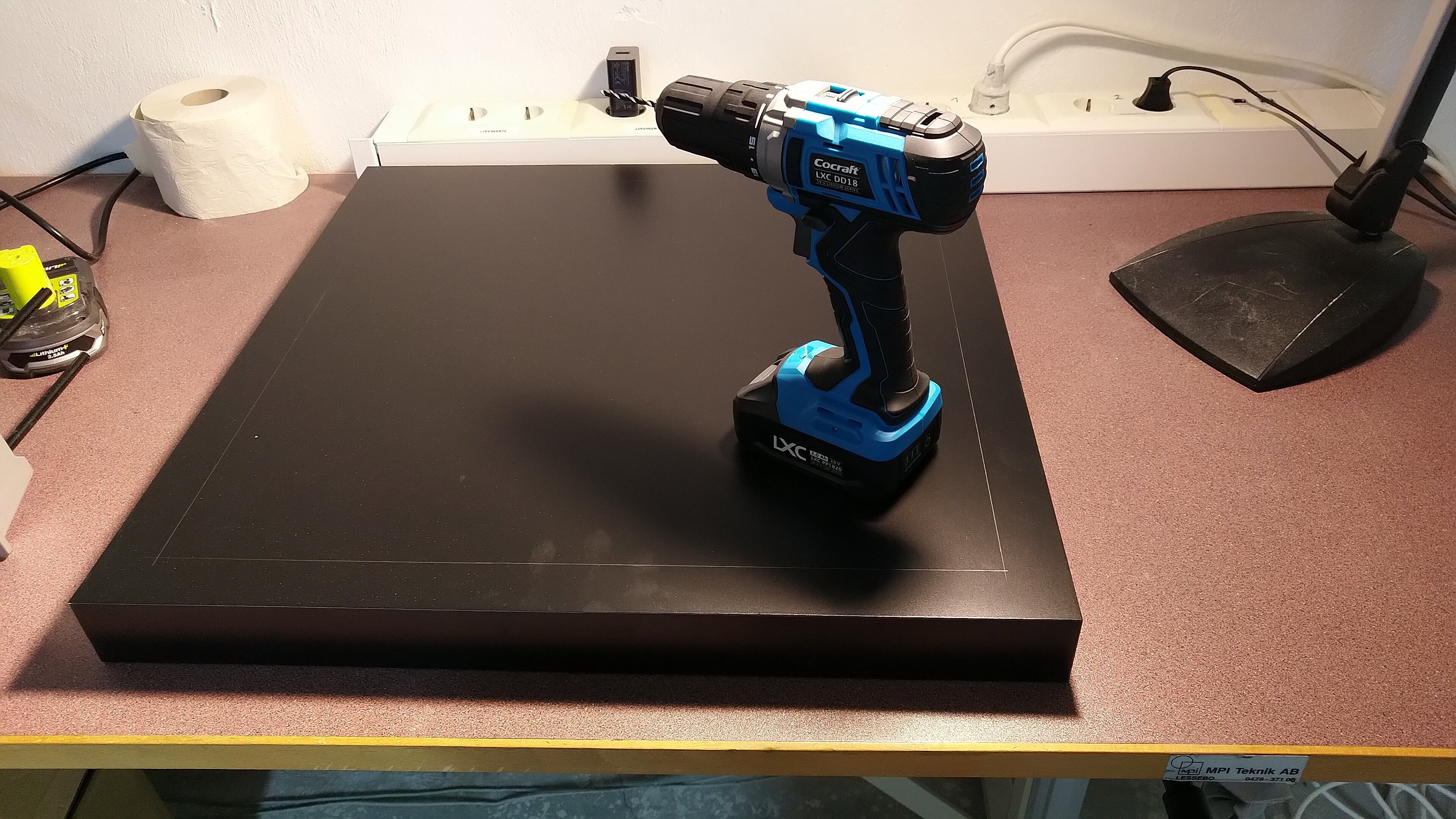
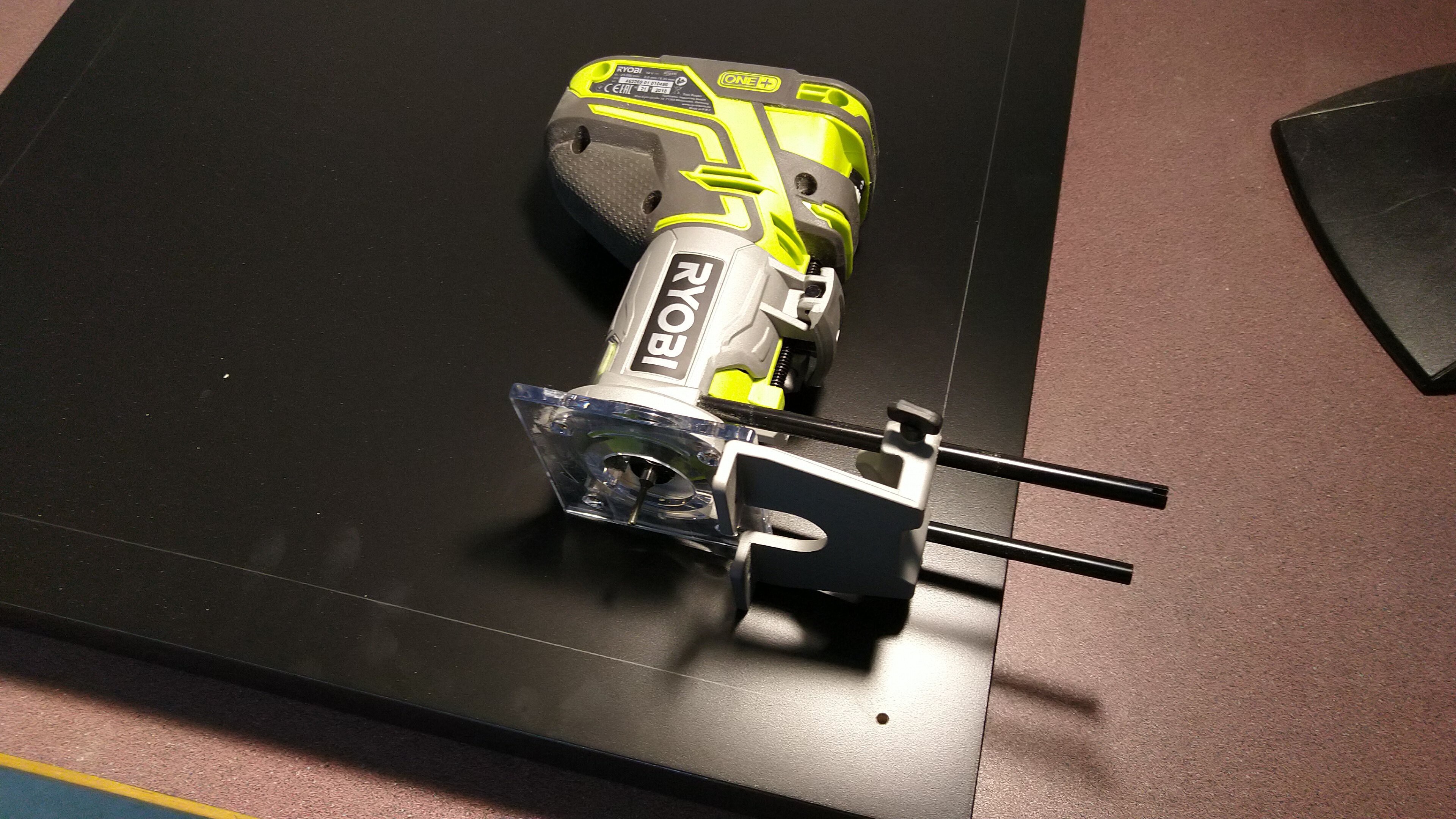
I moved over to the woodworking room and marked a hole in the corner for the router to enter.
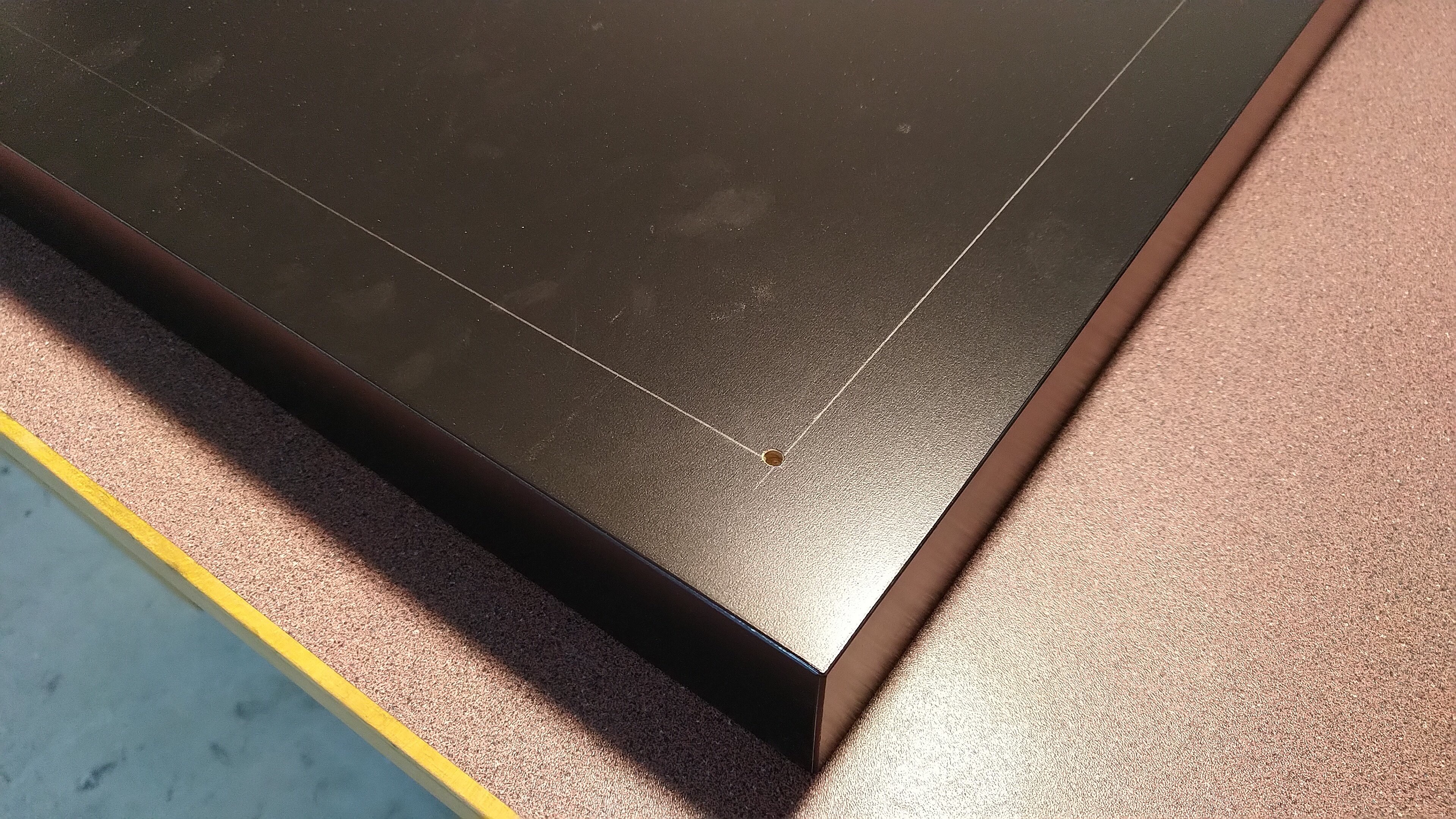
My initial try was with the narrow tool you can see in the photo below, however instead of routing it preferred to set the table on fire (I think it was too high rotation speed, but this router doesn't have speed control). So I switched to a v-score tool instead. That one worked great!
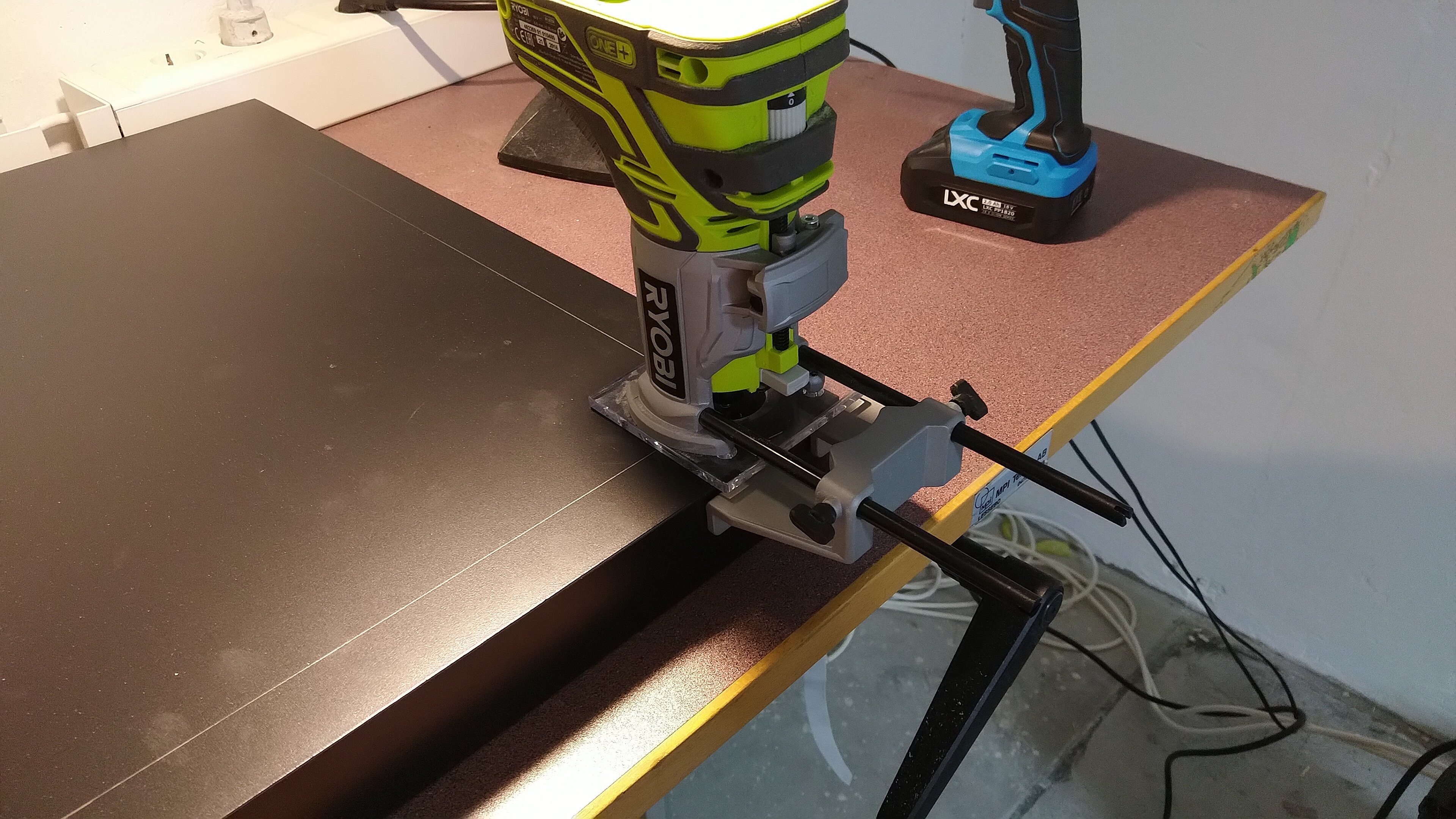
Here's a quick video of me doing the routing, watch out, it gets loud. You may also notice I screwed up one side when the router got a bit off-side, I fixed that later bu routing that side again but a bit closer to the edge.
And here we have all 4 sides routed, since I changed the tool to a wider one, I should've adjusted the margins a bit, so the actual frame I got was less than 3.5 cm, but it wasn't a big deal.
If you've never seen a Lack table's insides, here's a video for you, it shows how Ikea can make them so cheap, there's actually very little wood in there:
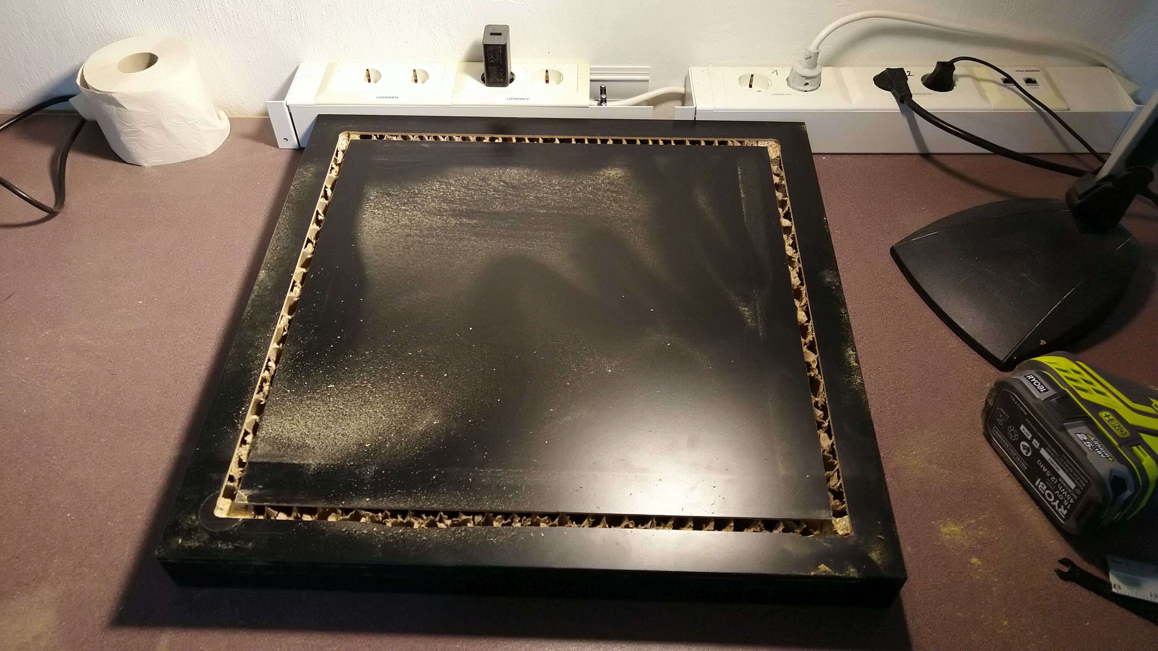
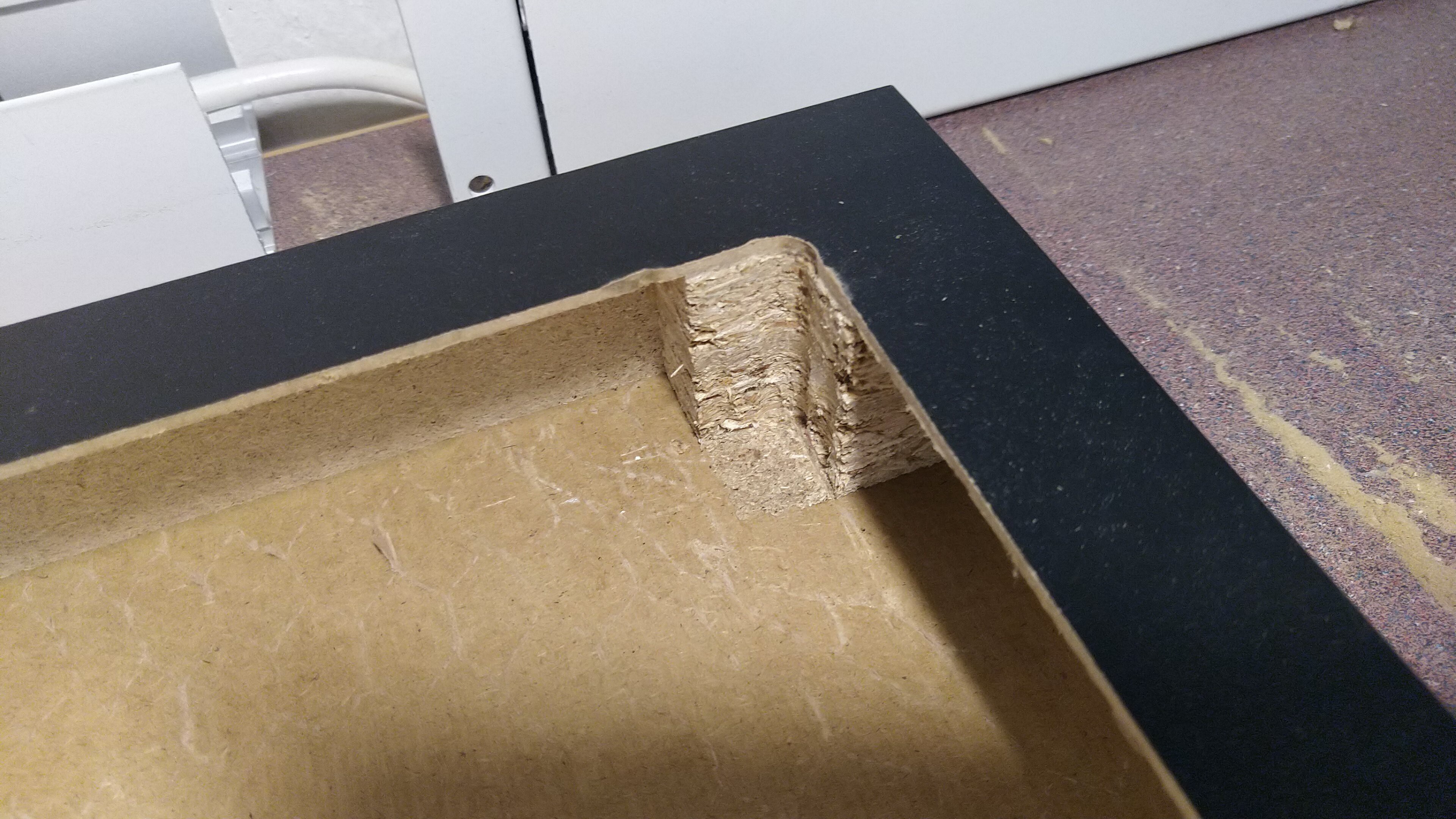
After that we had the frame almost ready. Notice the corners, there is still some particle board pieces in the corners that won't let the foam board go down.
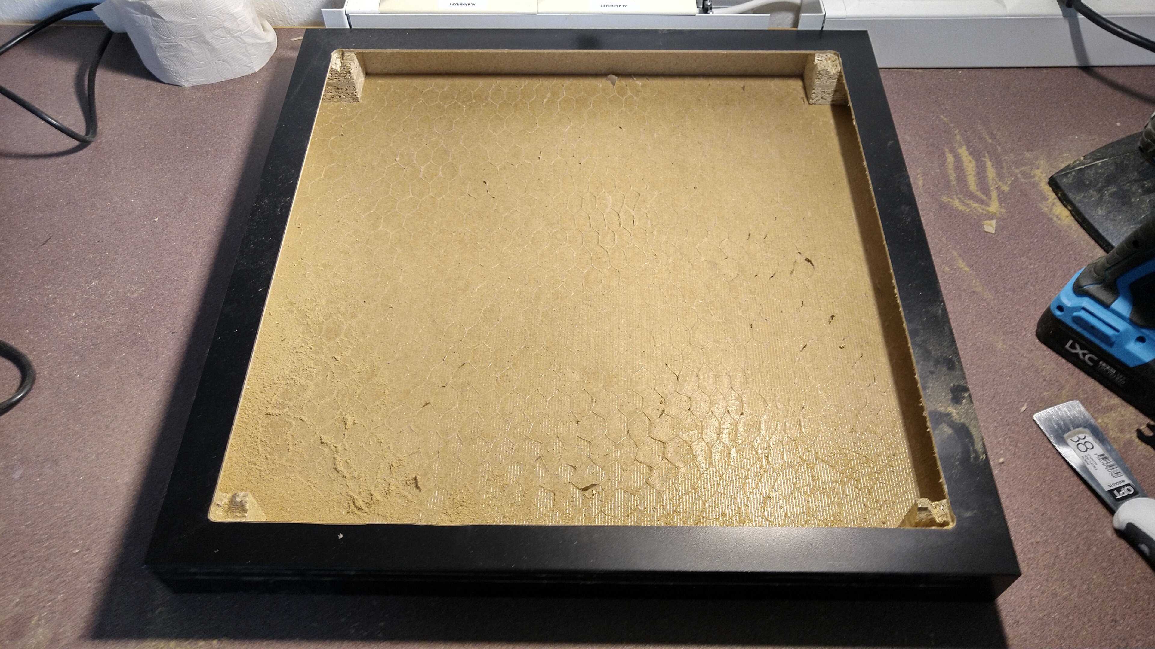
It took a while since I couldn't find a good way to do this, but eventually I got rid of the particle board in the corners and the Lack was ready!
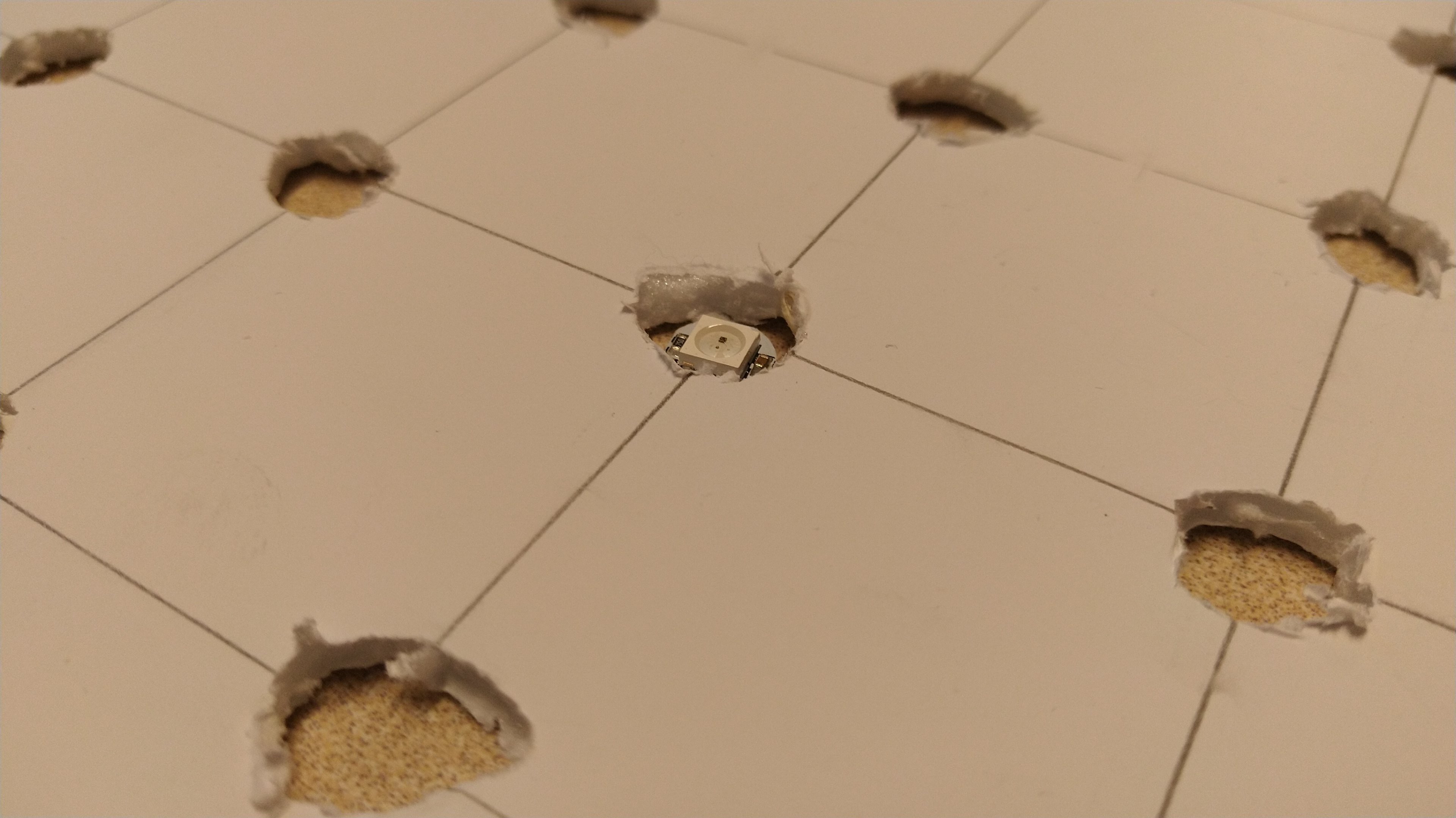
With that out of the way, I moved on to the LED part of the matrix. First, I needed a foam board to hold the LEDs, so I aligned a fresh foam board with the one made previously so I could mark the centers of the holes, that's where the LEDs would go.

Same procedure here, board was too small, had to tape an extra piece and cut to size.

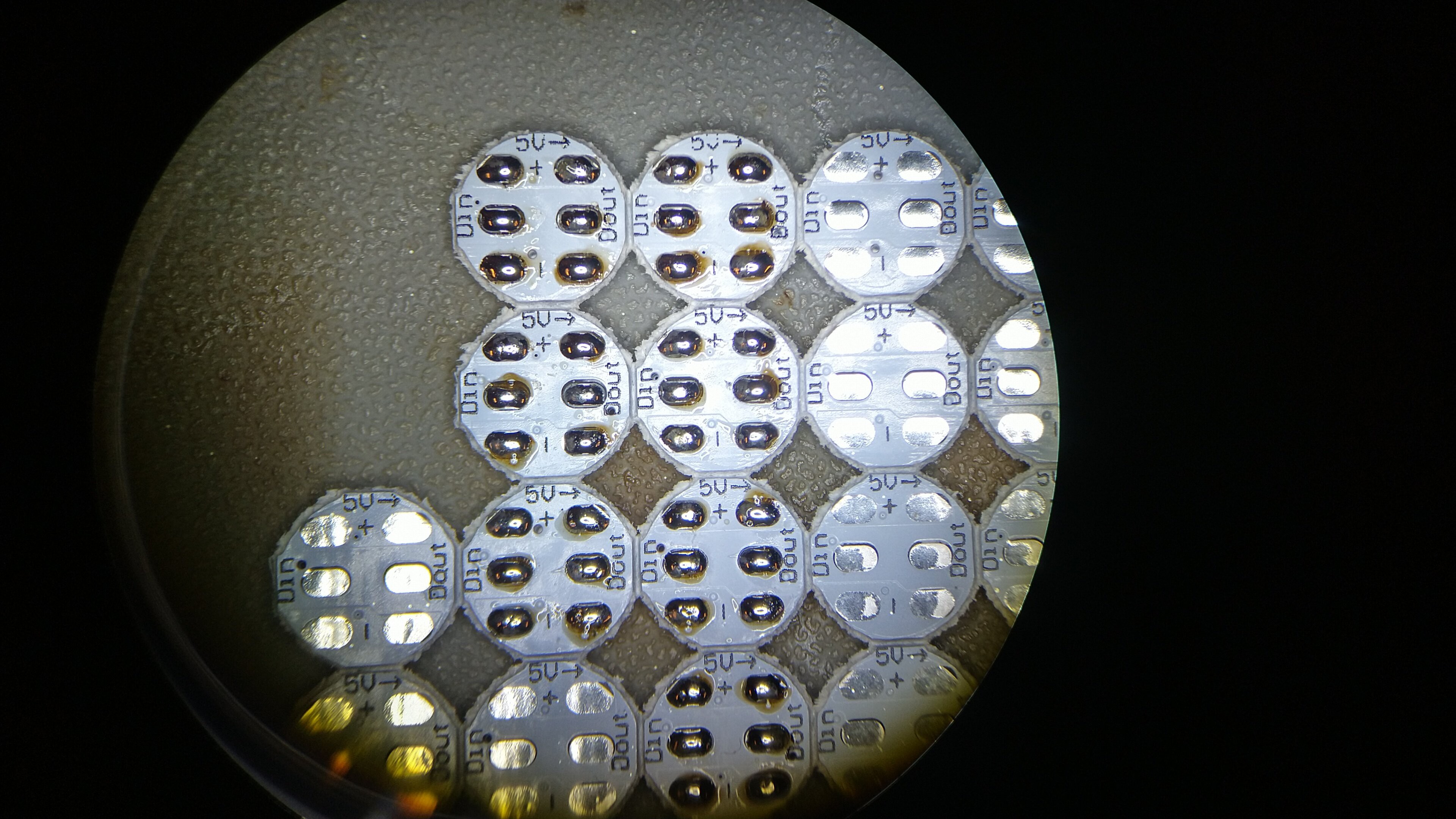
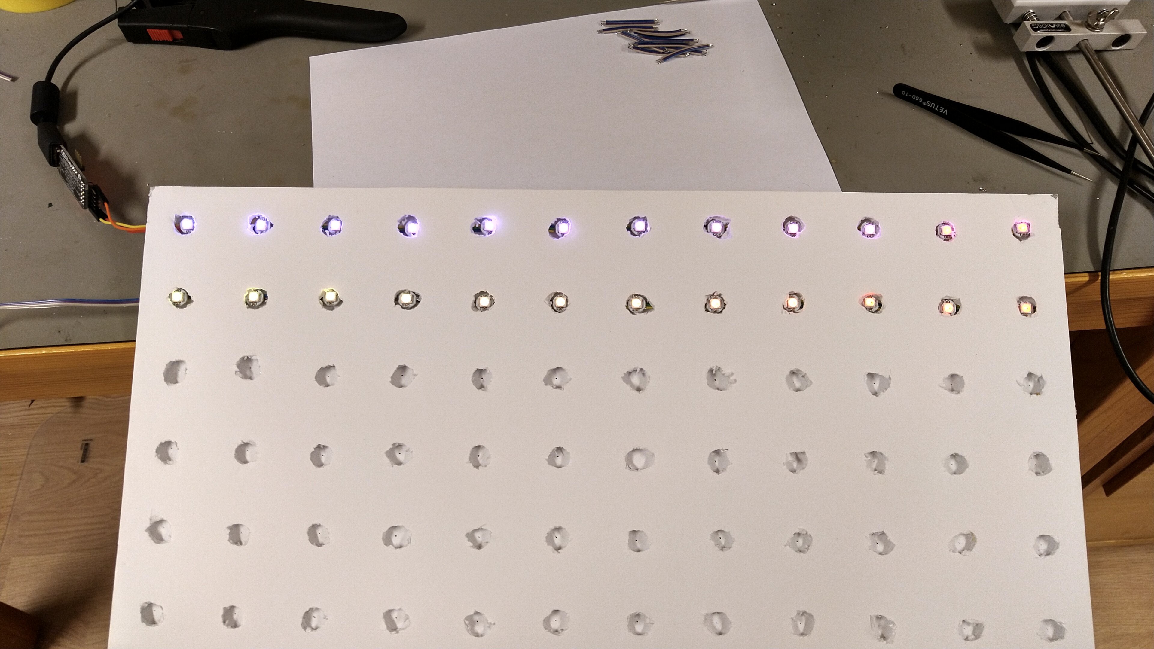
Now to the soldering! First I had to solder up the pads on the LED PCBs, that was quite fast since they were aligned nicely in the panel.
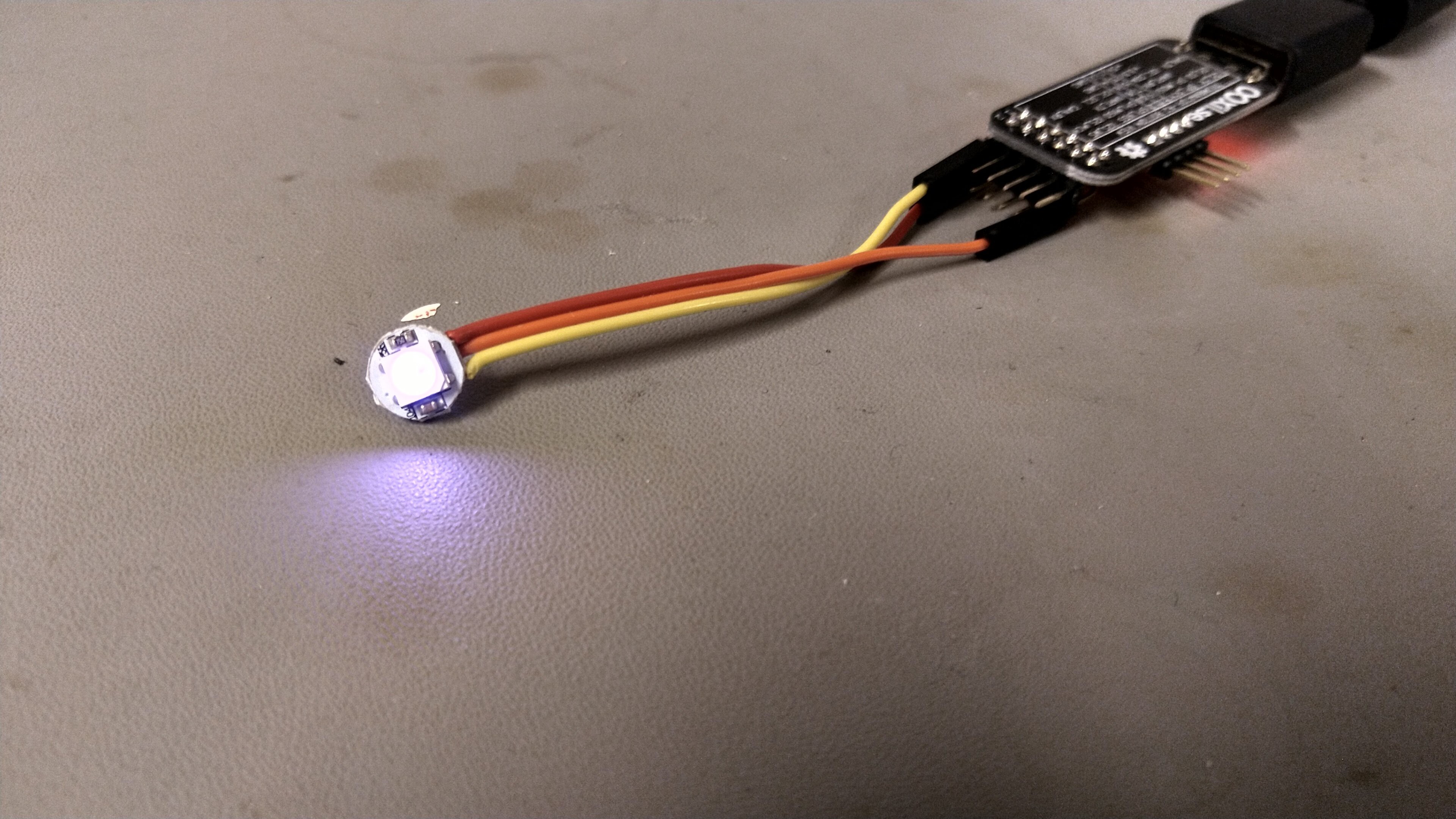
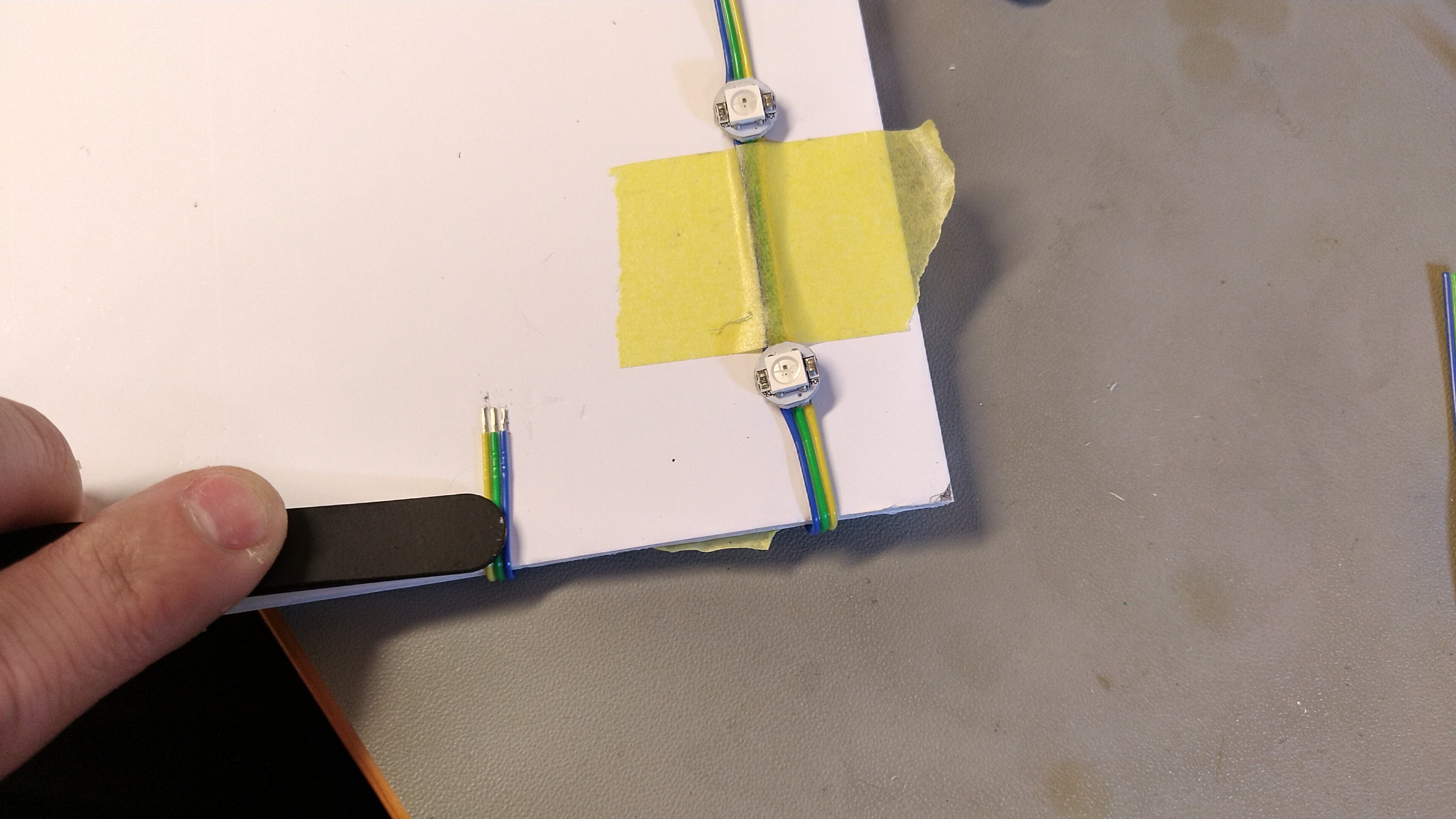
Then I soldered the first LED, it would be the beginning of the whole strip. I used @Konrad Beckmann's Thumbinator (STM32 board) for driving the strip as I worked on it. It just had a simple RGB chase animation running on loop.
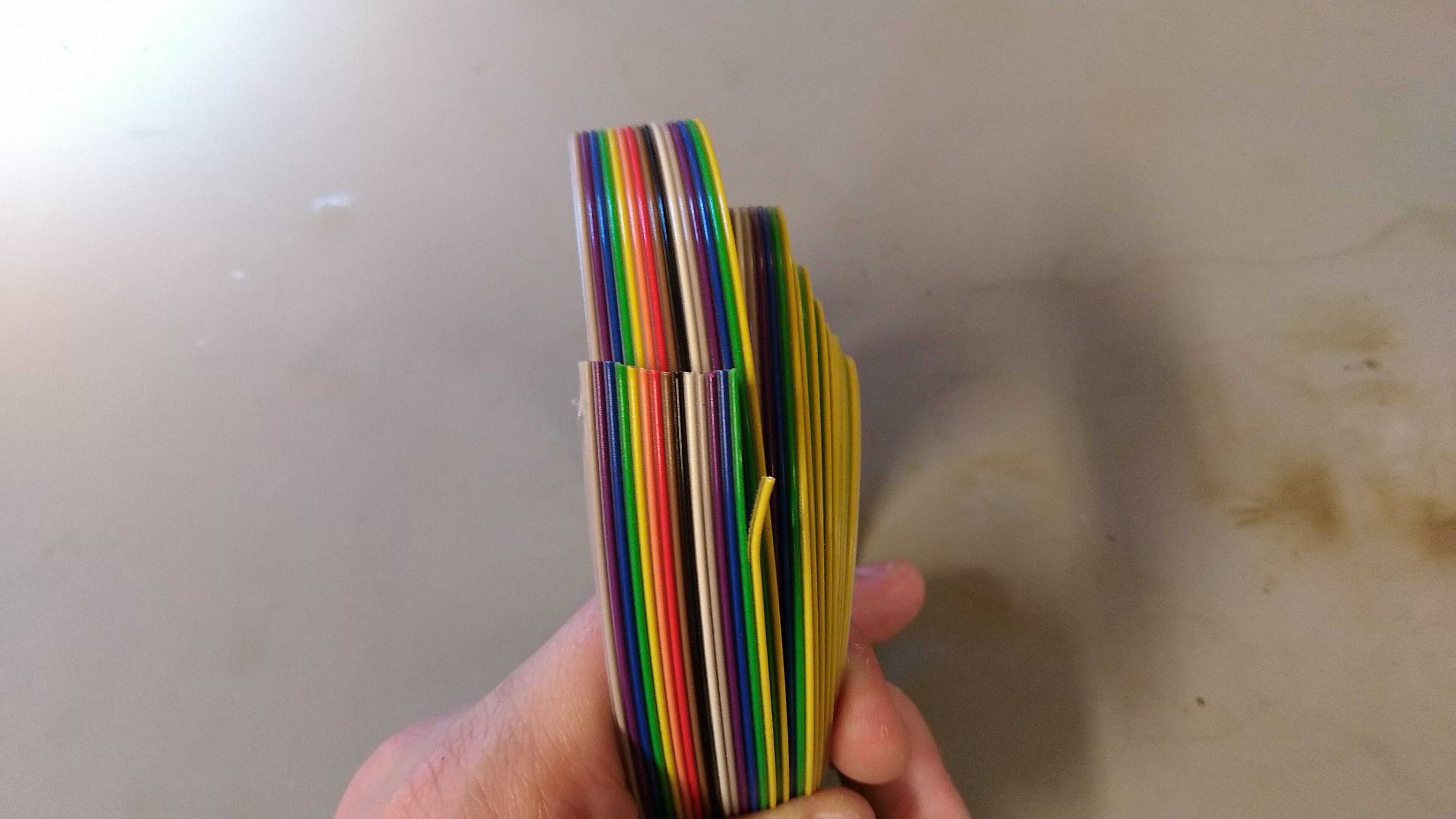
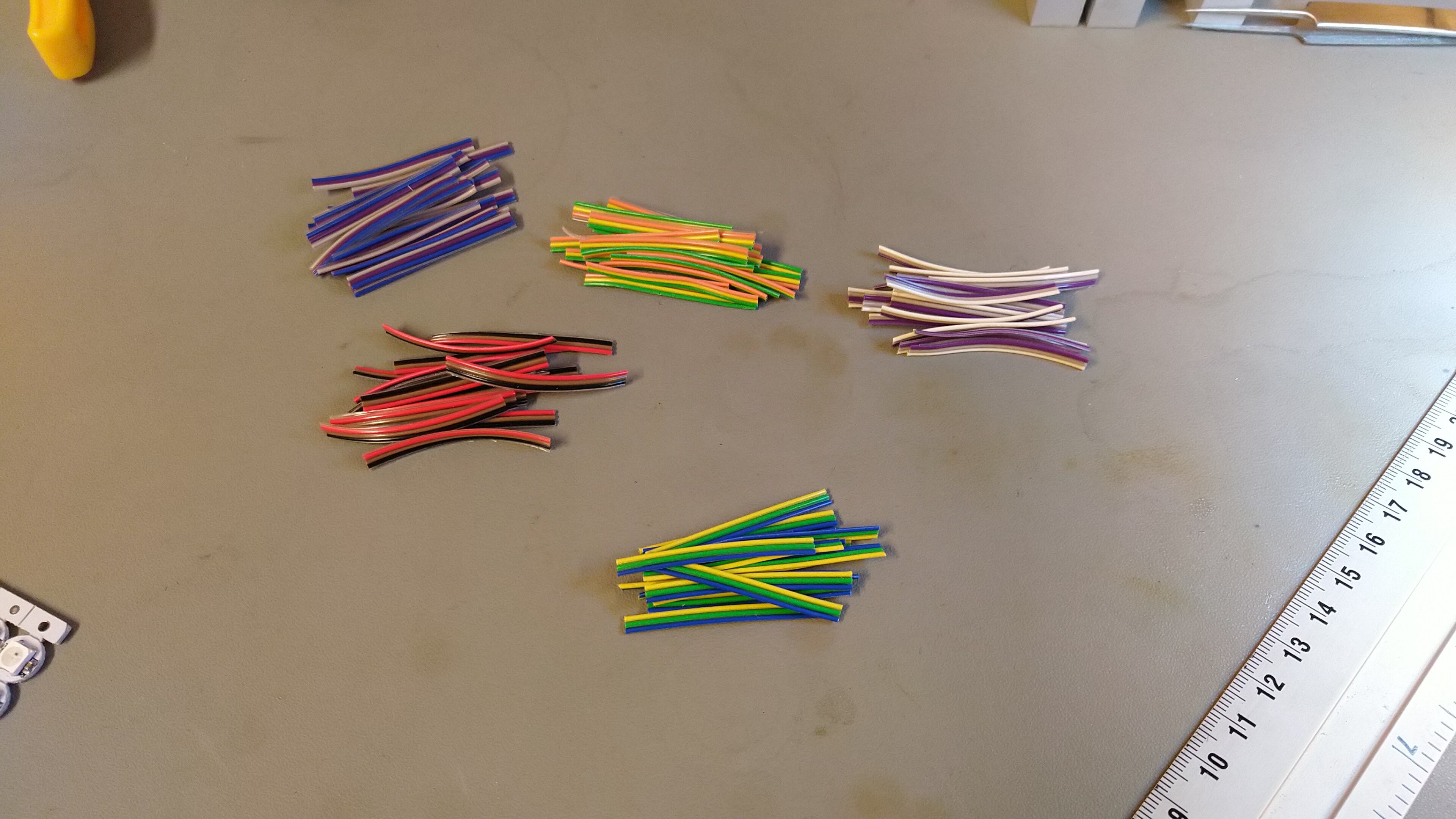
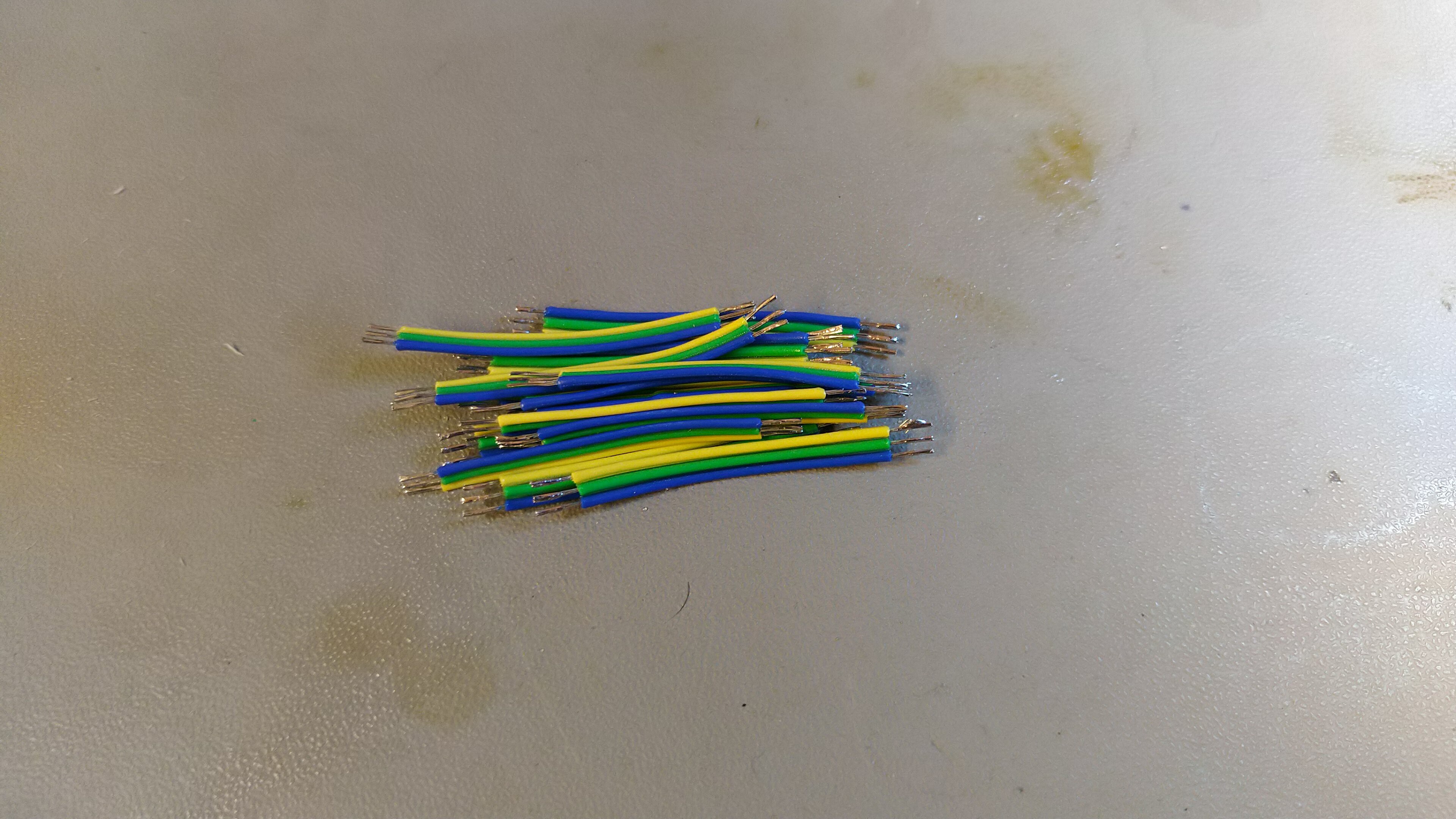
For creating the strip, I used some ribbon wires that I divided into groups of 3 and cut to size.

These are a few of the 4 cm pieces, but not nearly enough, I had to cut more later.
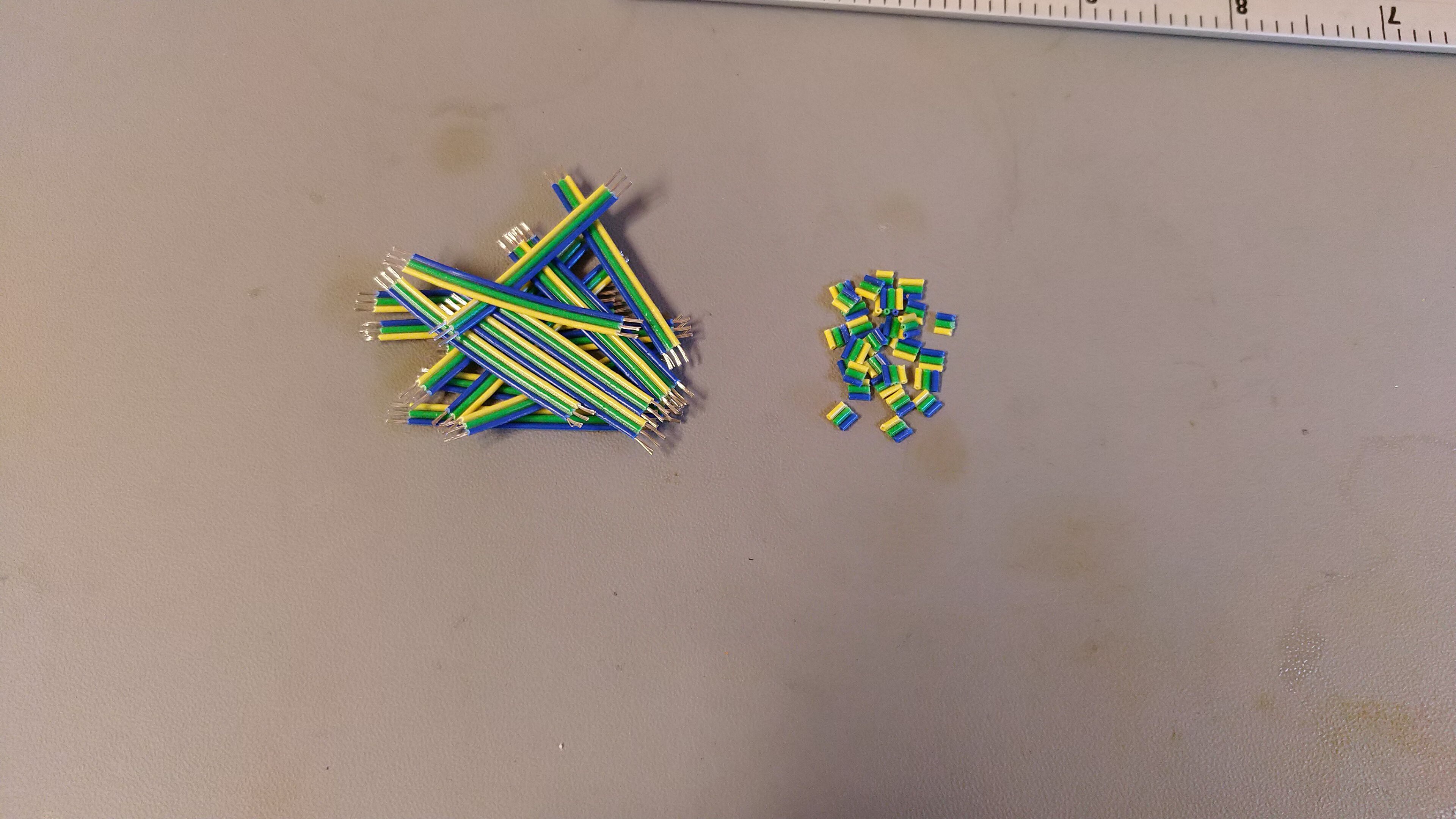
With the 4 cm wire pieces cut, I had to remove the isolation and wet them (apply solder).
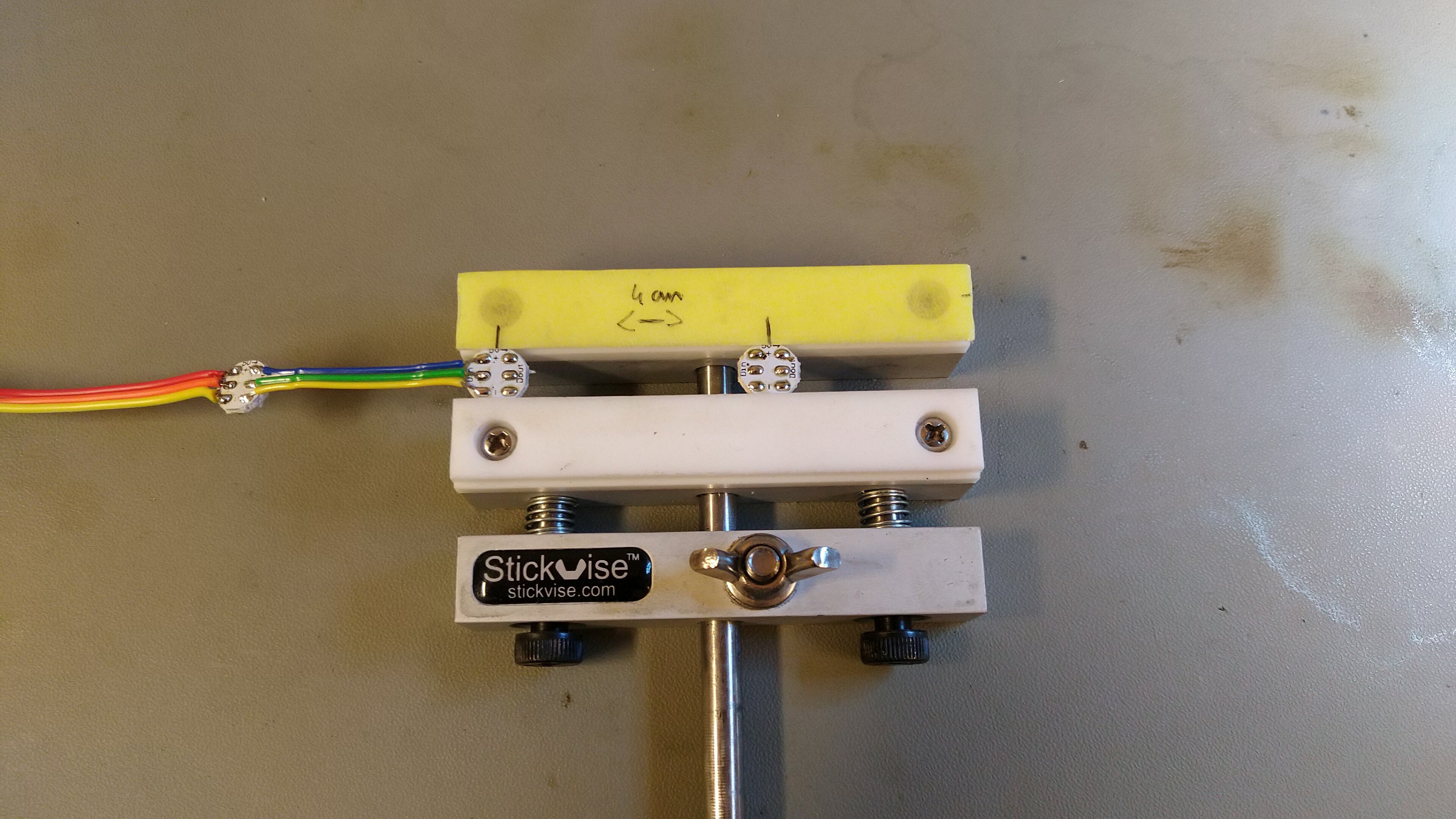
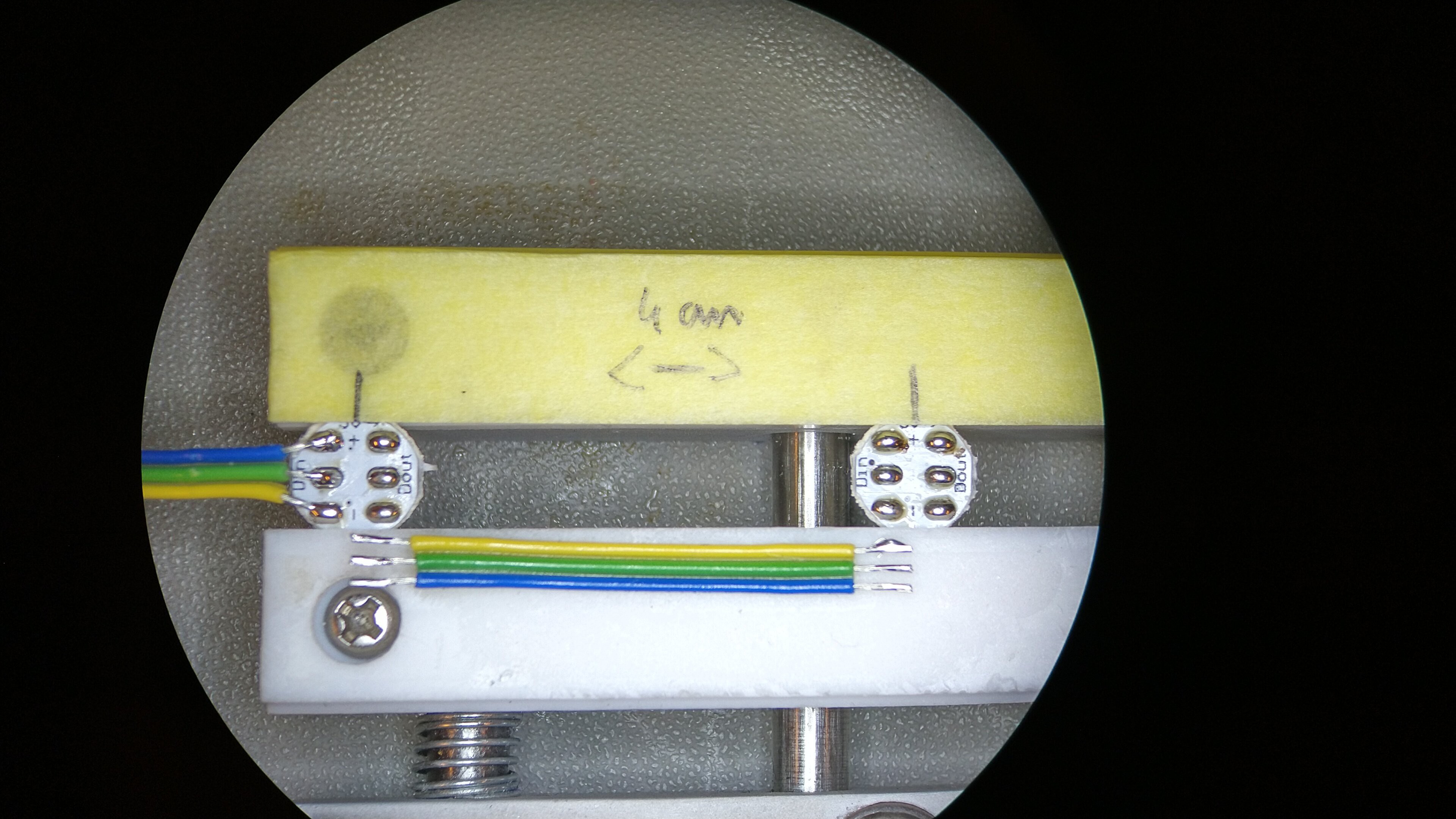
I made a quick and dirty (but very usable) fixture out of a stickvise, that allowed me to make sure that all LEDs were exactly 4 cm apart.
I then proceeded to solder the strip, I took a lot of time and in hindsight, I should've went for PCB + stencil. I could've gotten large PCBs (16 x 16 cm) made and used those. Oh well, next time!
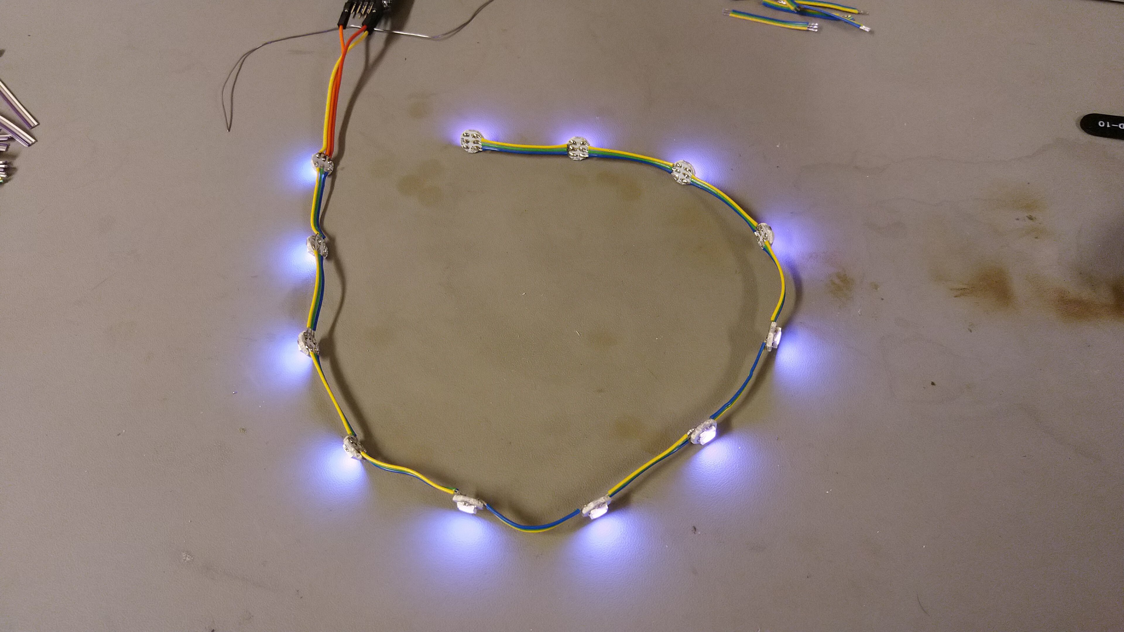
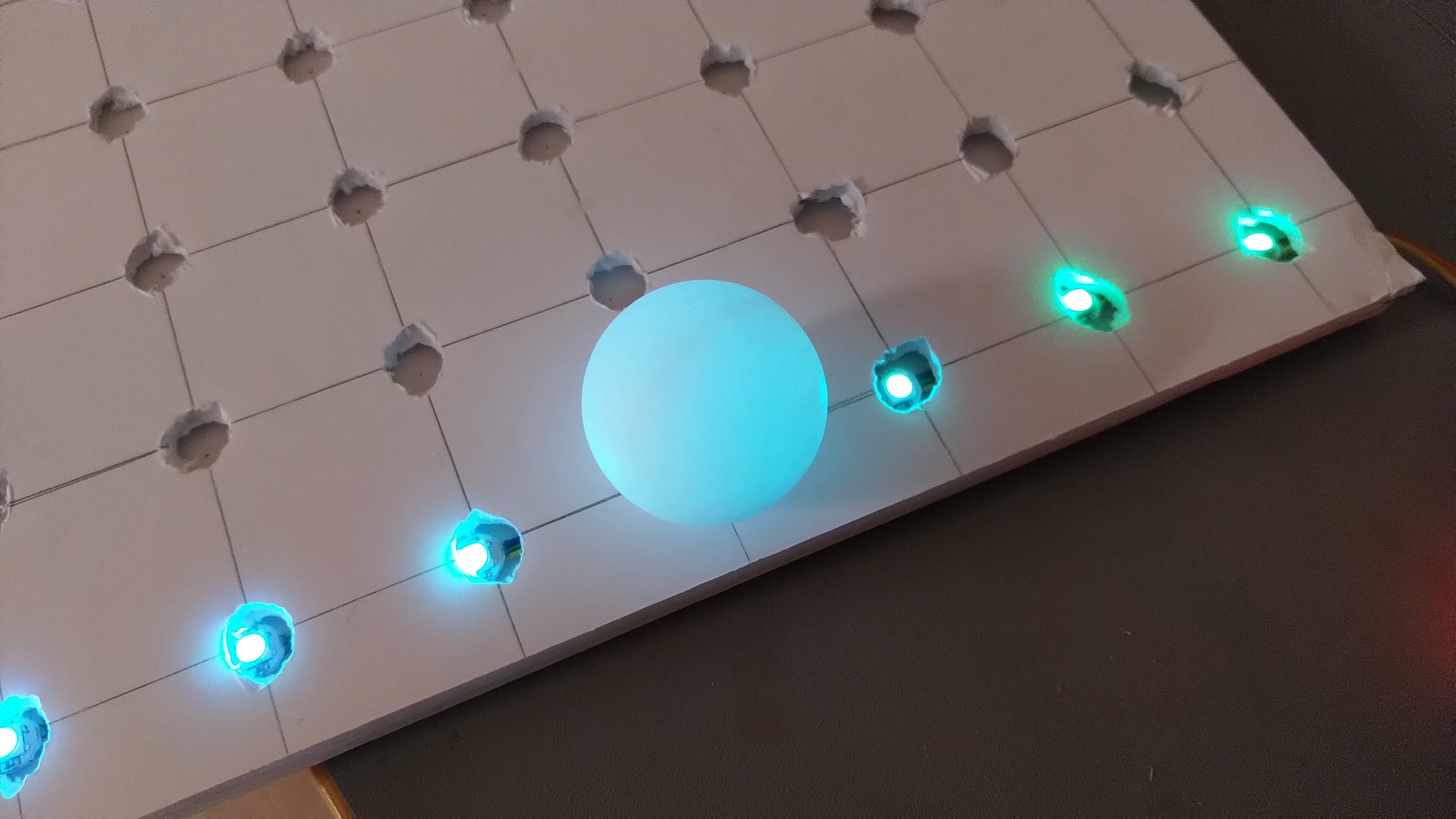
With the first strip of 12 ready, I could test the look of the thing with a ping pong ball that I made a hole in.
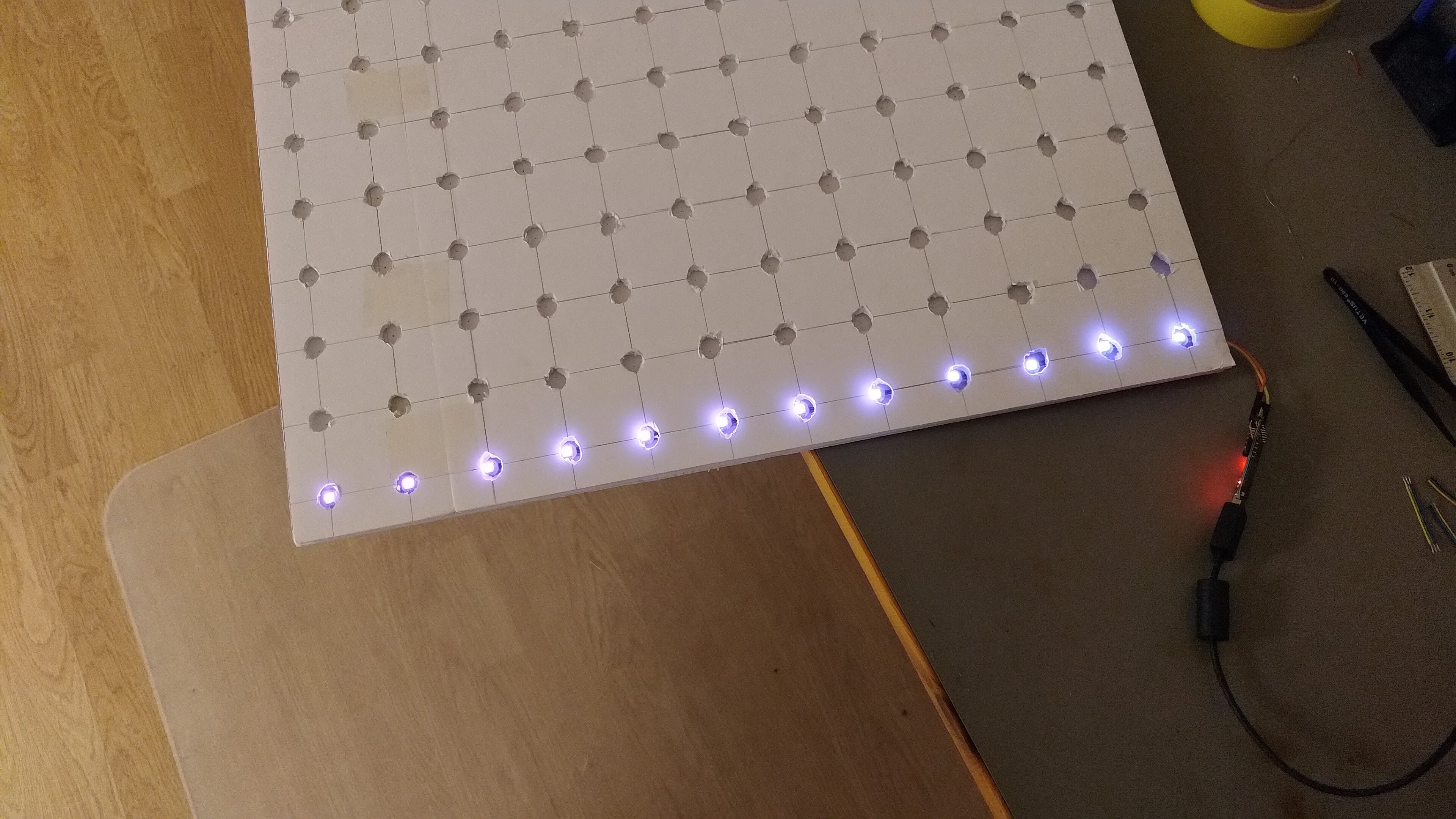
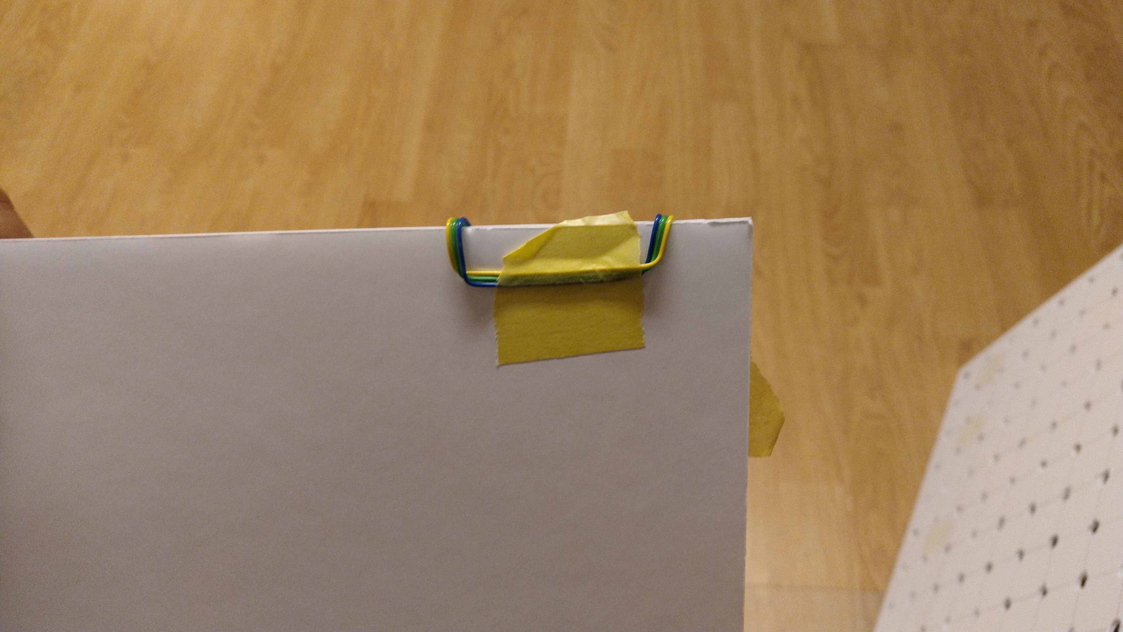
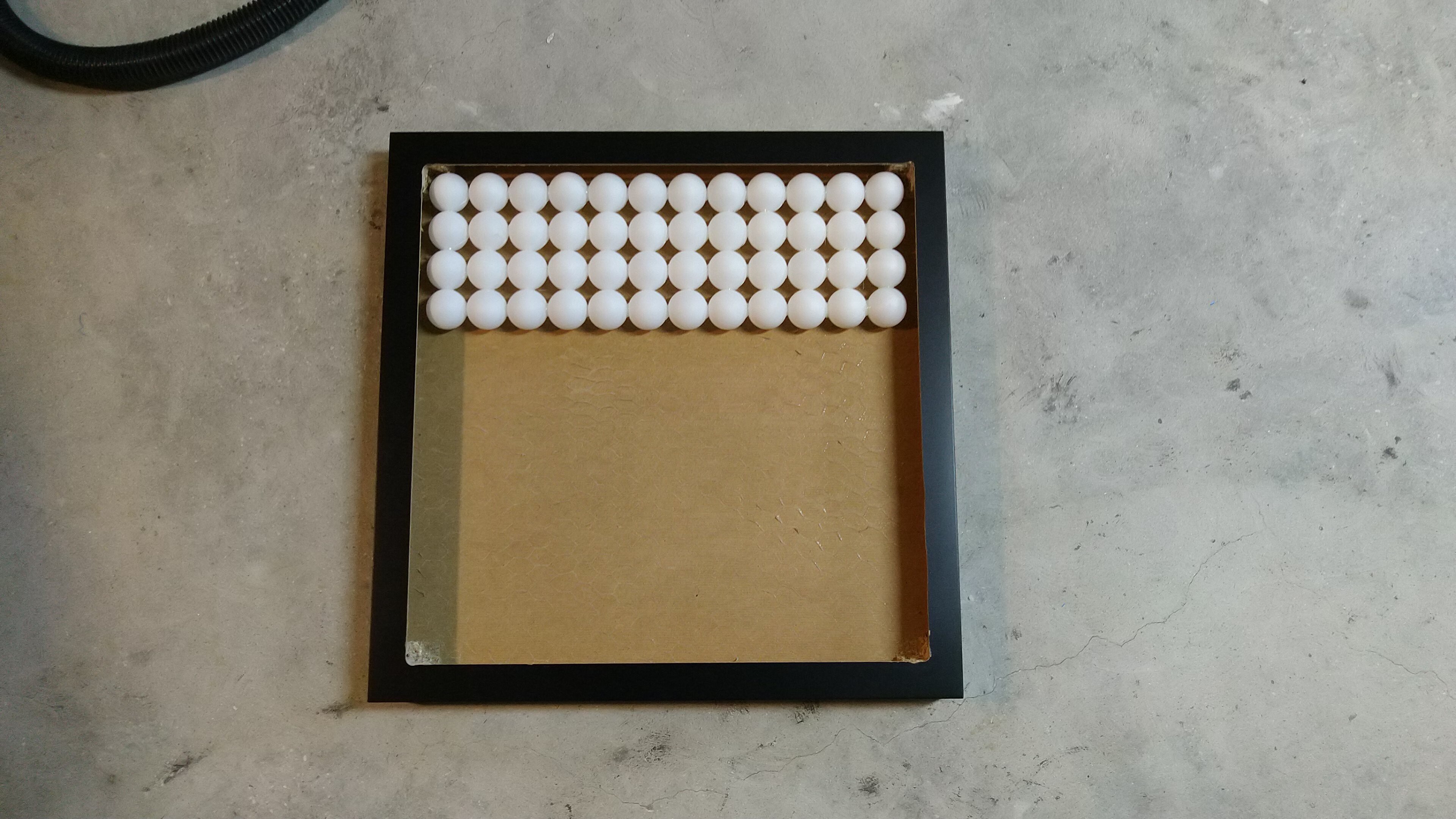
It looked good! Now, because we reached the end of the foam board, we had to turn around, creating a snaking strip, this was later fixed in SW so the every other row was backwards, a common method used with LED strips. I used masking tape to hold everything in place.
Then we had 2 rows!
And 3 rows!
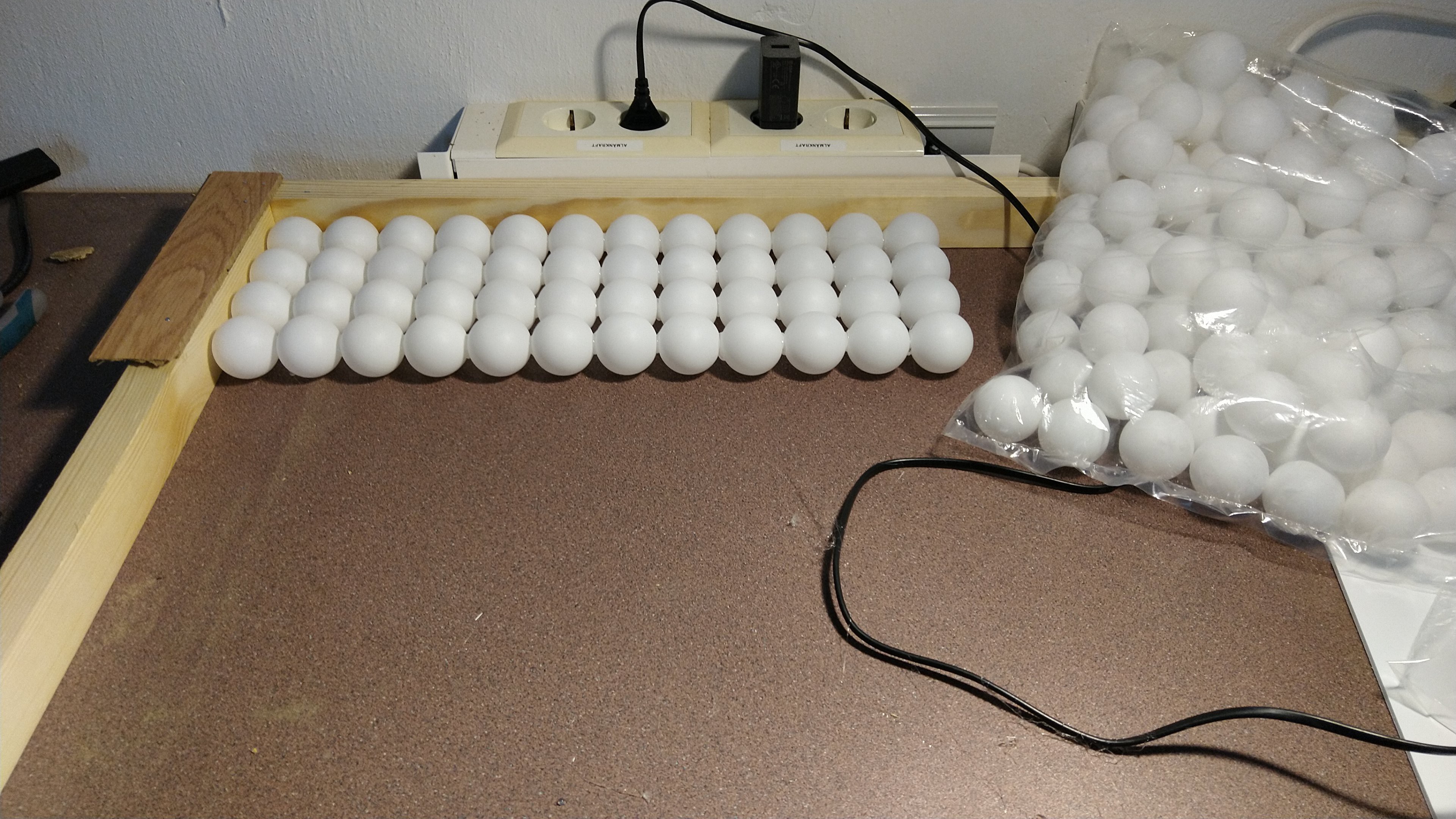
After soldering for a few hours I felt I wanted to get a break so I moved on to the ping pong balls. I made a simple 90 degree fixture so I was able to glue to balls together straight. I used hot glue for that.
Because I was anxious to see the effects of my work, I made a quick 3x3 matrix and tested it with the strip I made so far, it looked good!
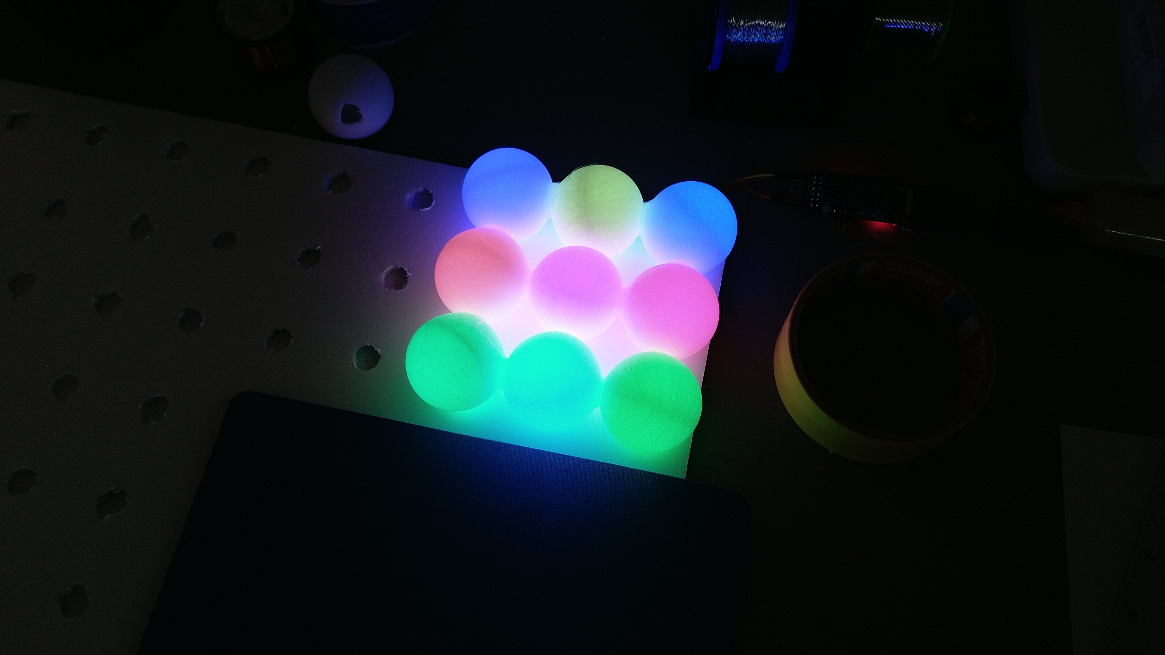
Motivated by that I quickly glued together more of the balls.
And a quick fit-test, so good so far.
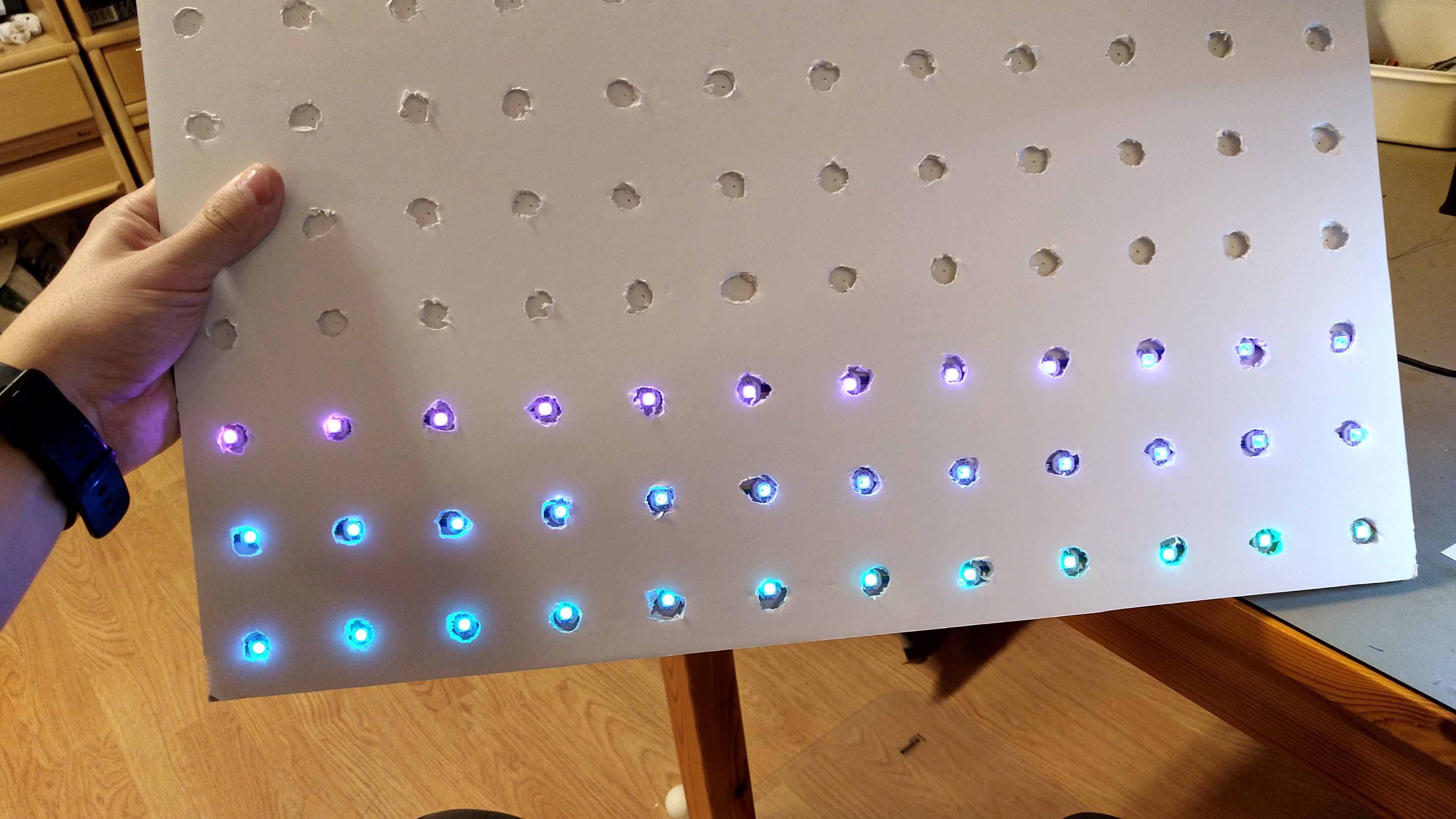
With this newfound motivation I powered through the rest of the LEDs and the 12x12 matrix was done!
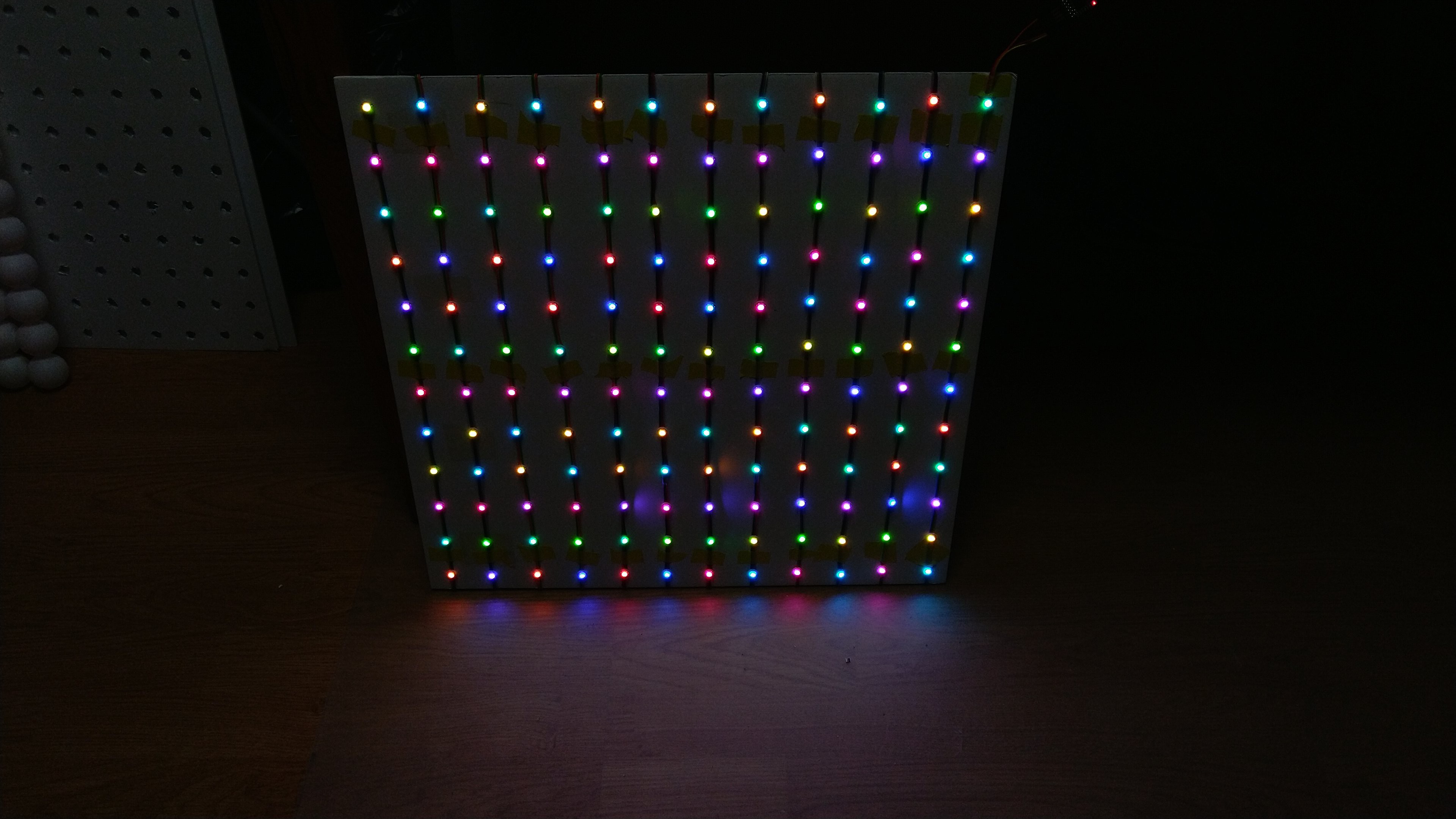
Adding the second foam board, the one with the holes, added a nice tunnel/diffuse effect.
Another fit-test, still good.

And back to the ball gluing. It went fairly fast.

Once that part was done, I made sure everything fits together and moved on to creating holes in the bottom of the holes, so the light could shine inside. For this purpose I used a soldering iron tip. I aligned the balls and the foam and started poking. Note: if you're gonna do this, make sure you're in a well-ventilated space, those plastic fumes are not fun!
When I was done with the holes, I got a nice surprise, the melted plastic fused with the foam board so they became a single piece, this made alignment a lot easier.
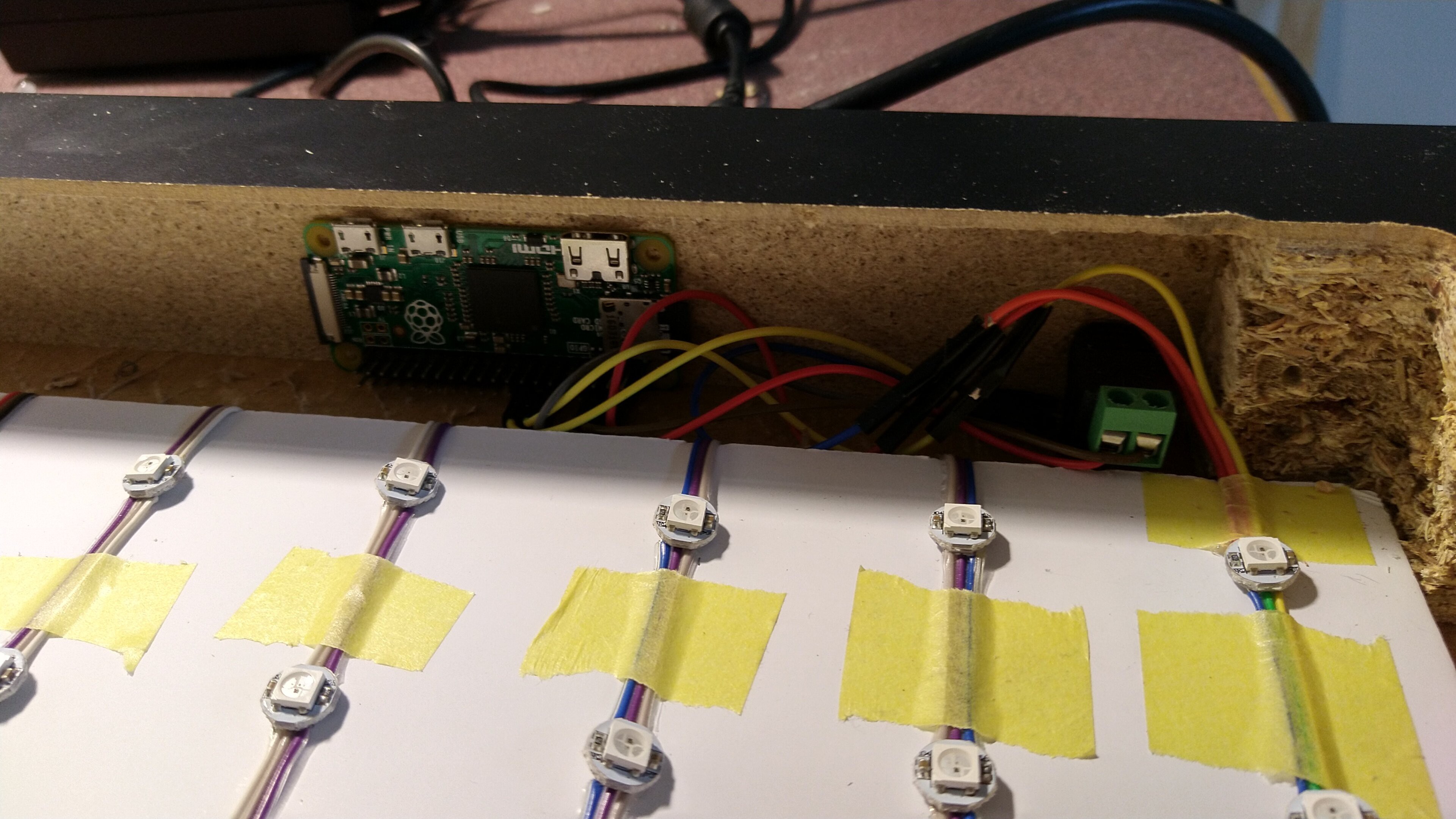
I could then move on to the software. I flashed the latest Raspbian on a Pi Zero and compiled the library mentioned before. Since the LEDs work better with 5V IO, I used a MOSFET to control them. I set up the matrix driver to auto start during boot so I didn't have to do anything after the whole thing was assembled.
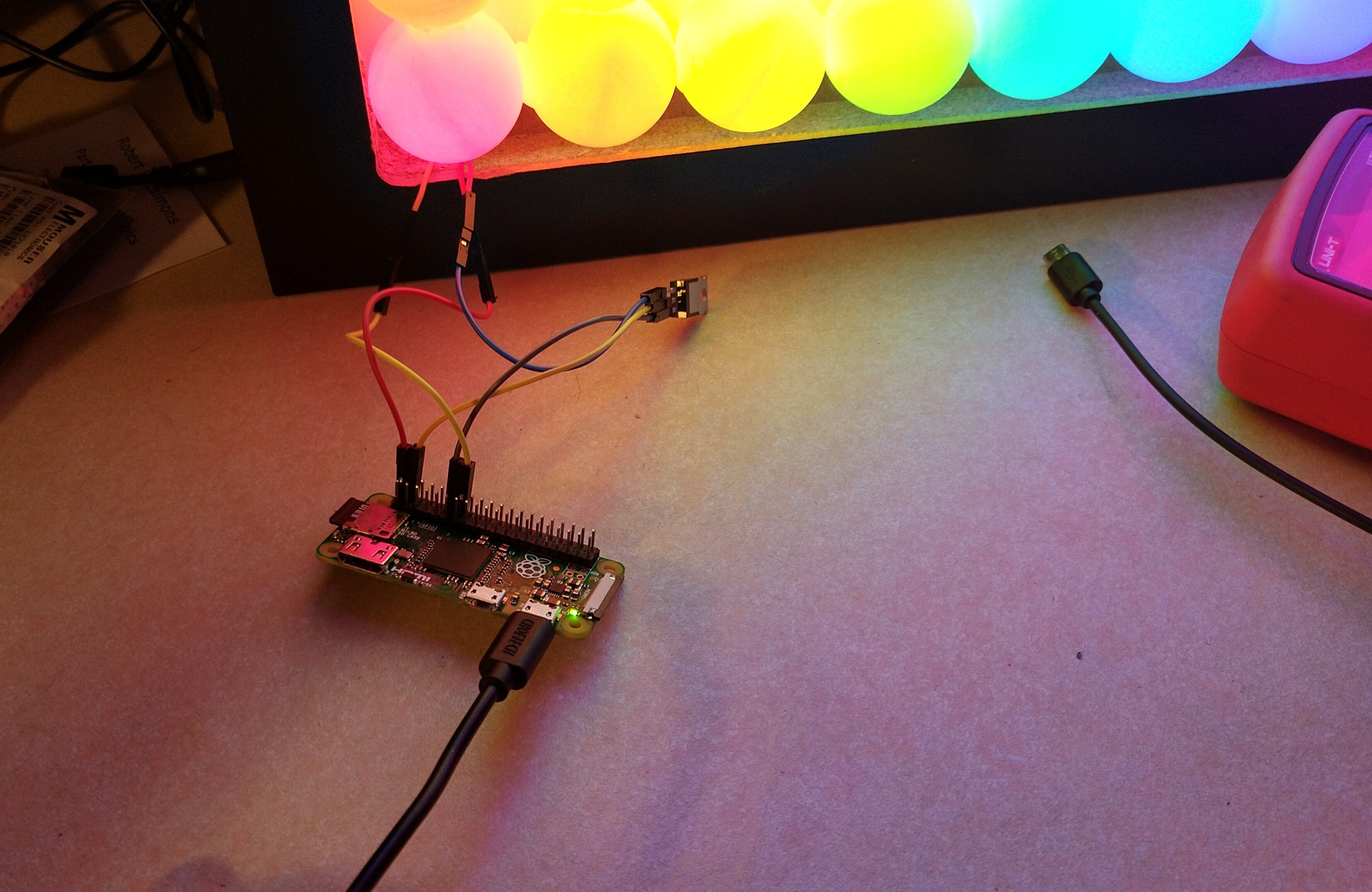
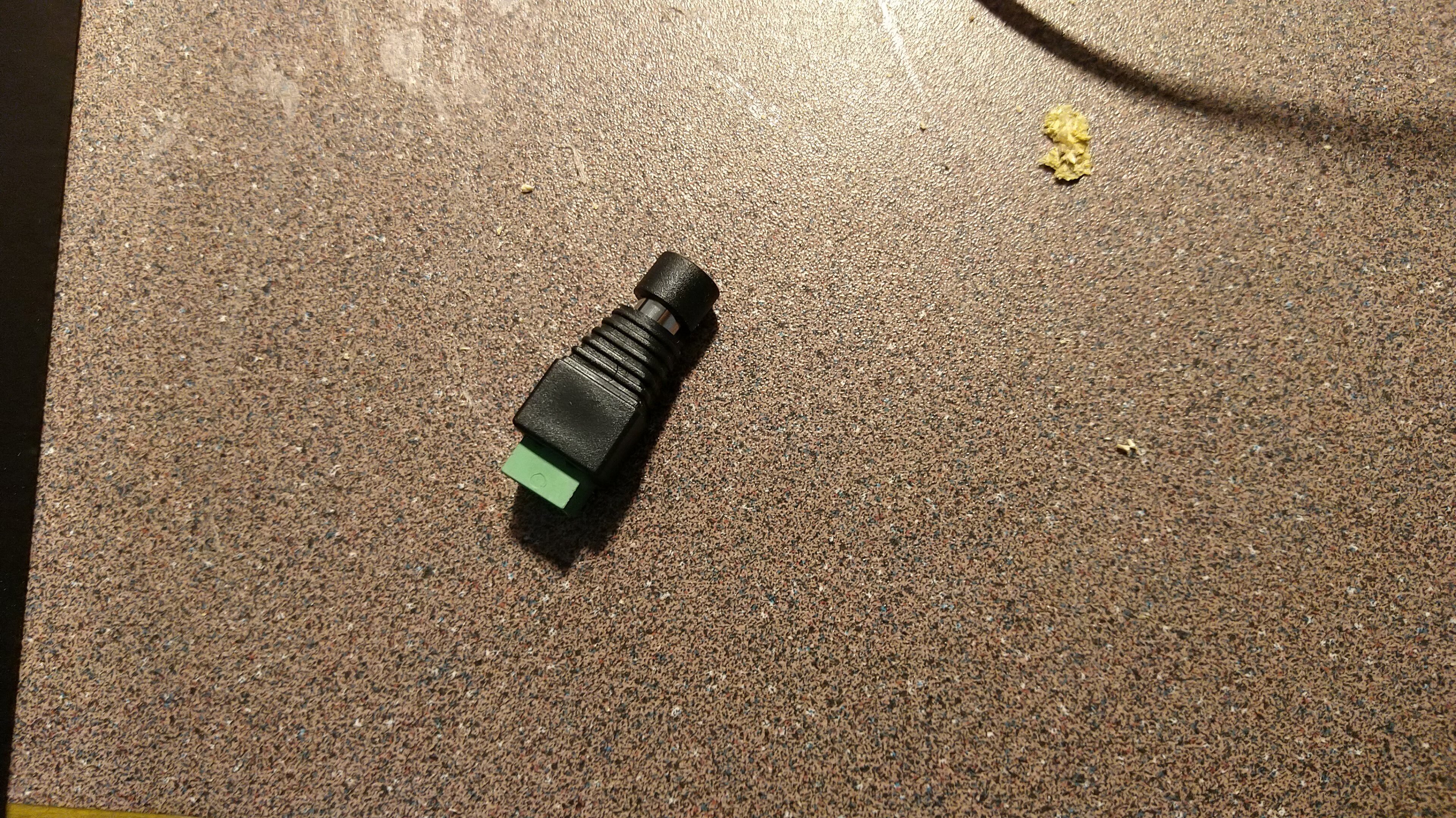
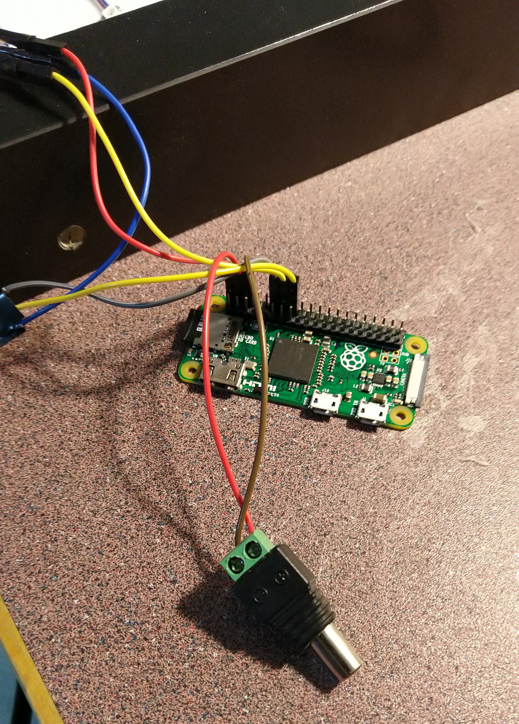
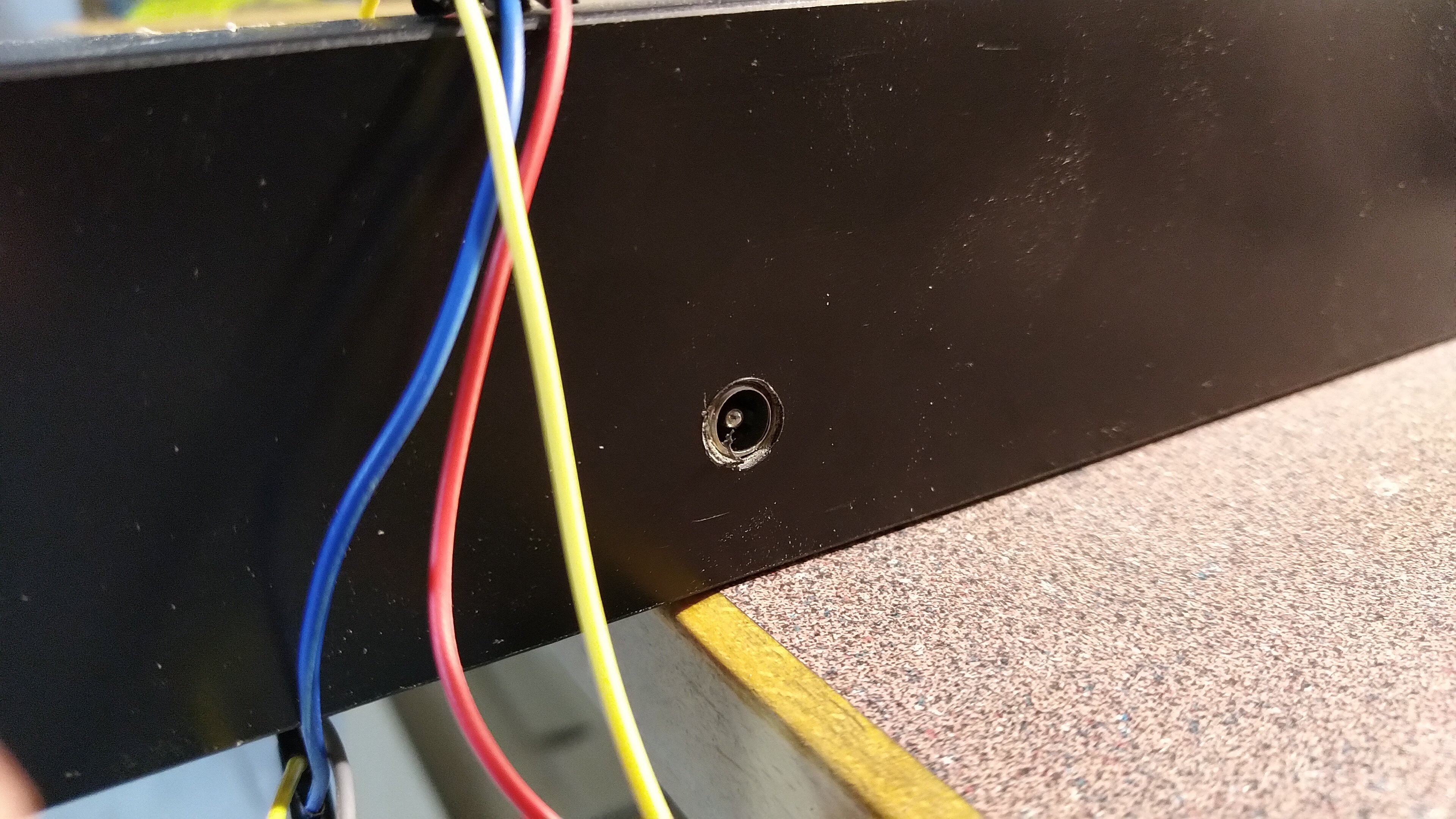
Then I realized, it would be nice to have some power going on in there. I got one of those barrel jack-to-wire terminal sockets and connected it to the Pi.
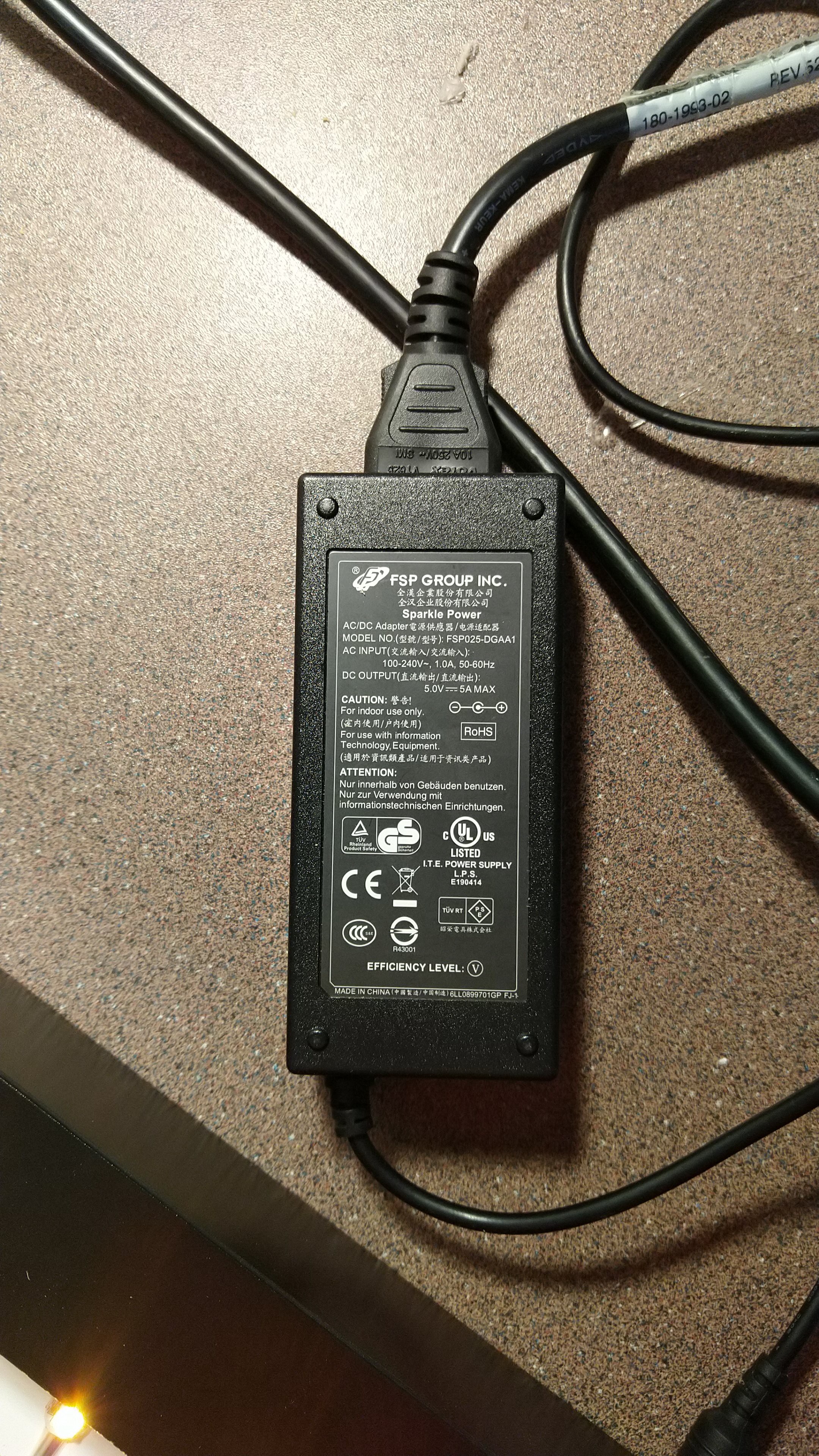
This is the power supply I used, had it in the hackerspace from some other project. 5A should do just fine.
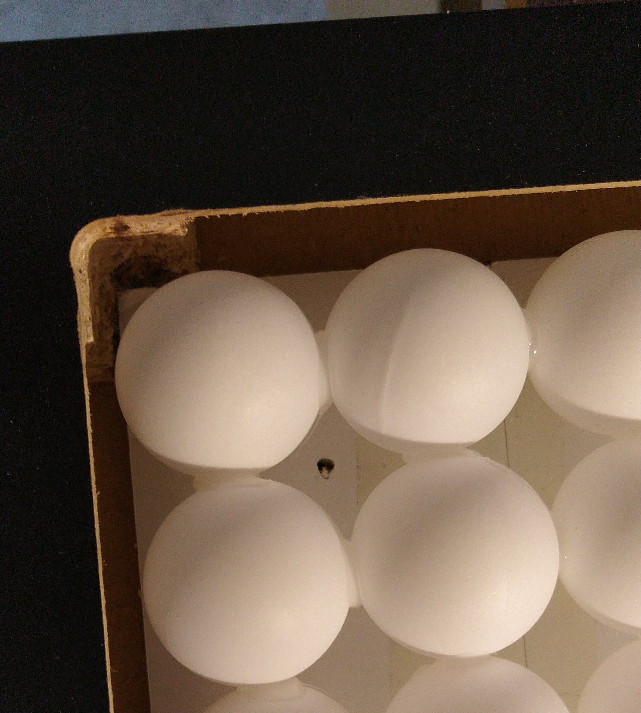
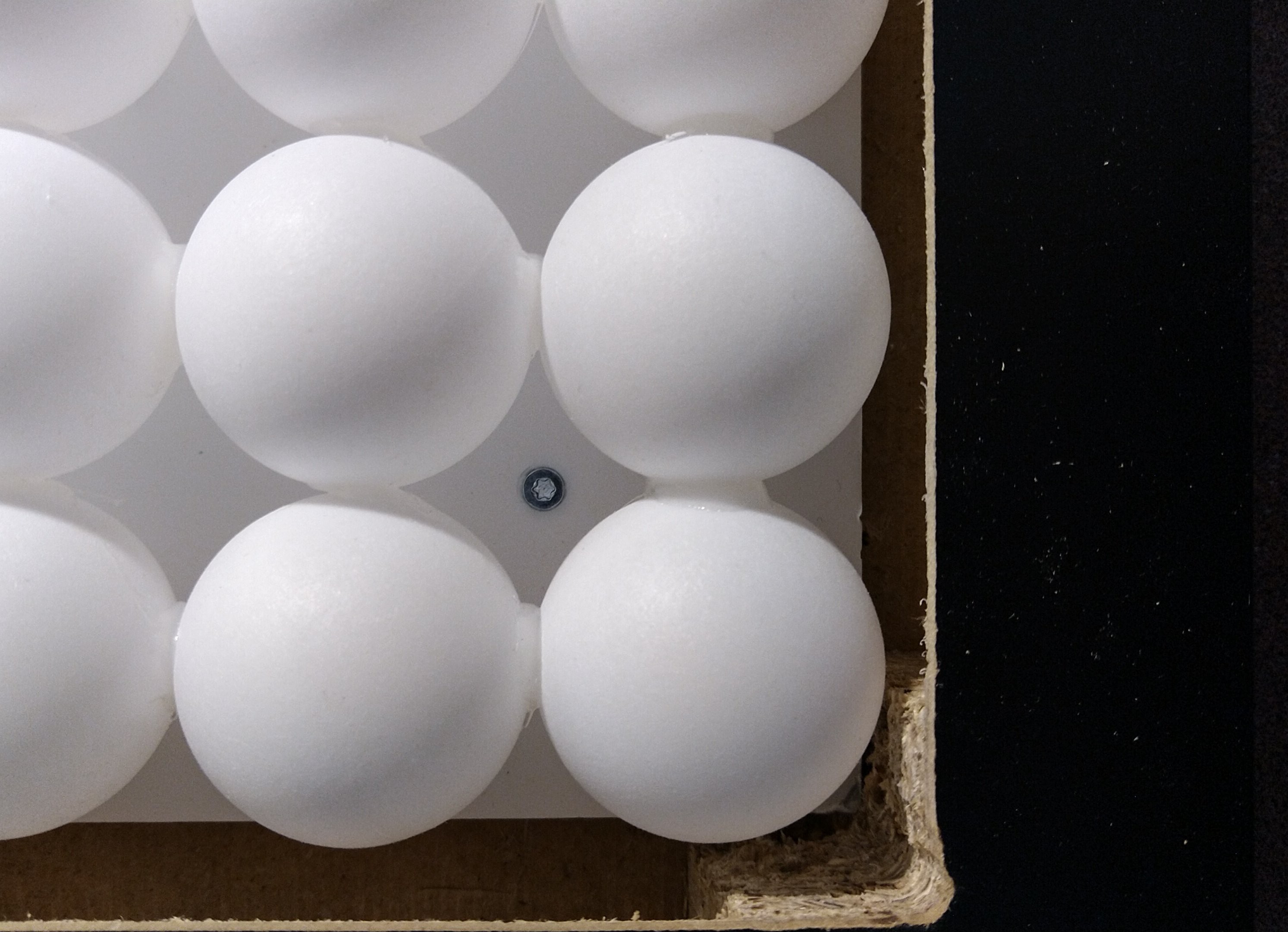
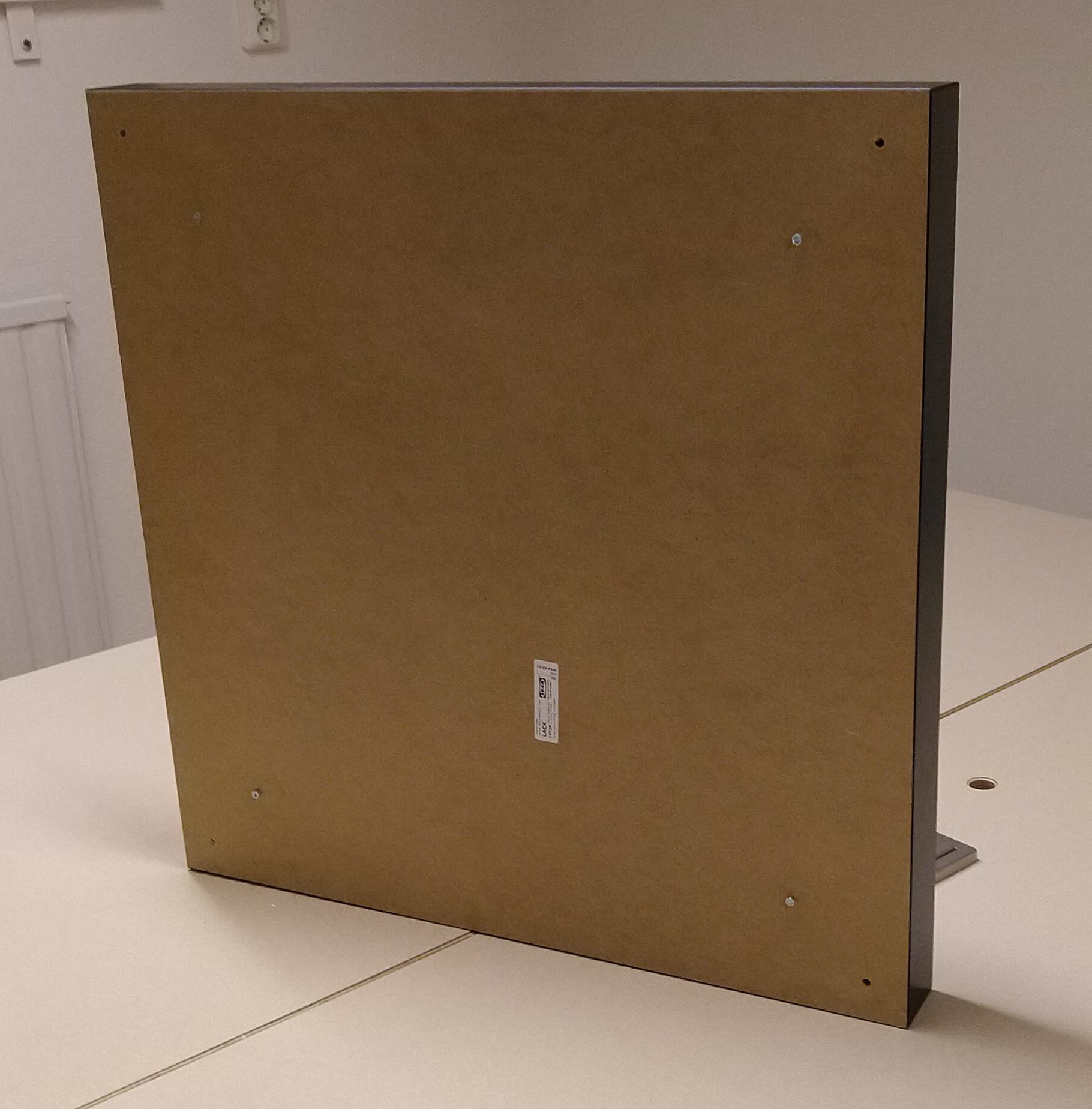
The last thing was to make sure the insides stayed in place so I drilled M3 holes in the 4 corners of the matrix and screwed the thing with 4 screws.
Once I assembled everything, I realized that hmm, actually it would be nice to have access to the Pi without taking stuff apart. I was using a non-W Pi so WiFi was not an option (also I didn't want to waste time with SSID setup and such). So I connected a simple UART-to-USB dongle to the Pi and used the terminal to make the changes I had to. After doing that I could tuck the dongle inside the matrix and retrieve it easily without taking the whole thing apart.

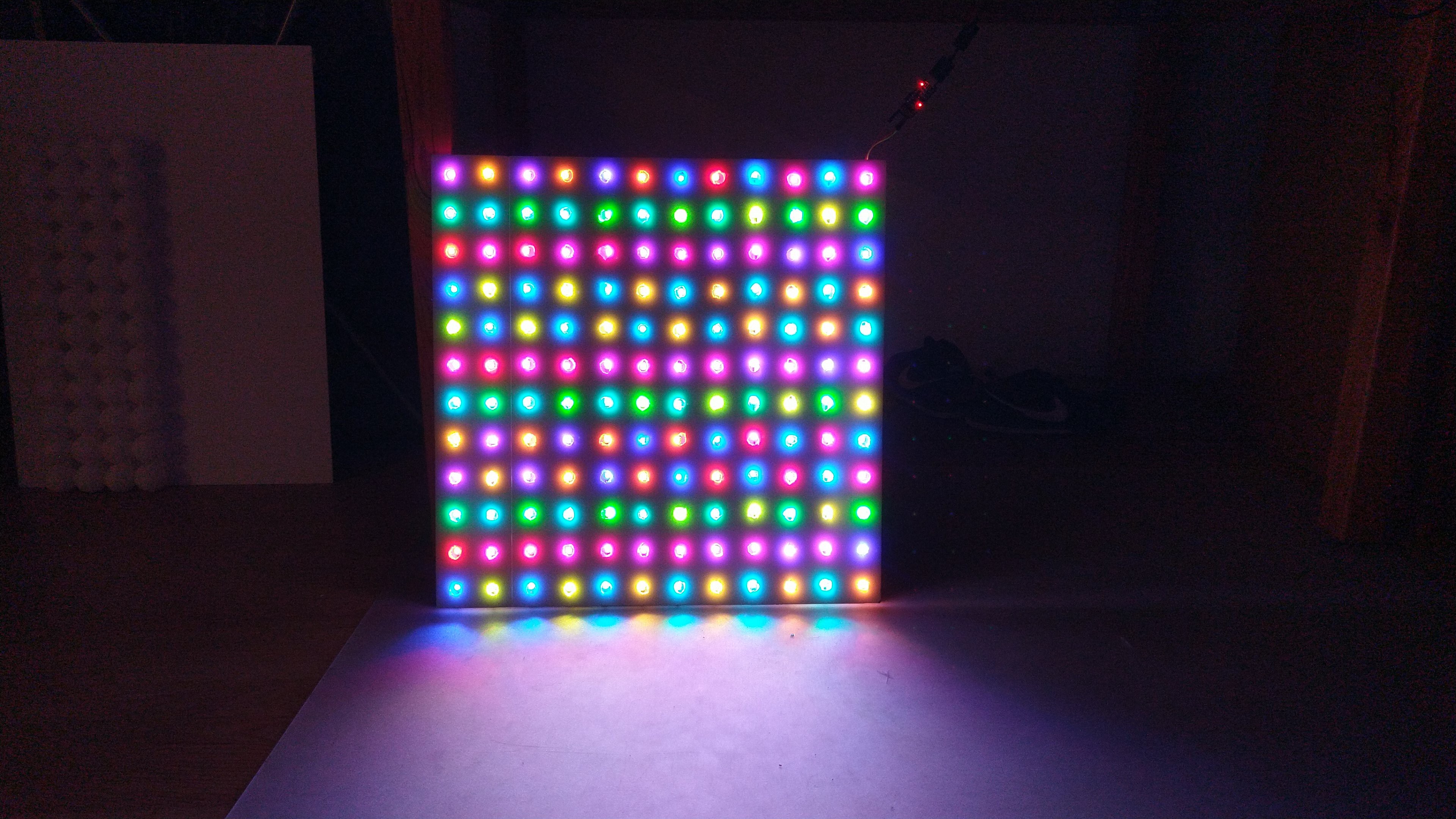
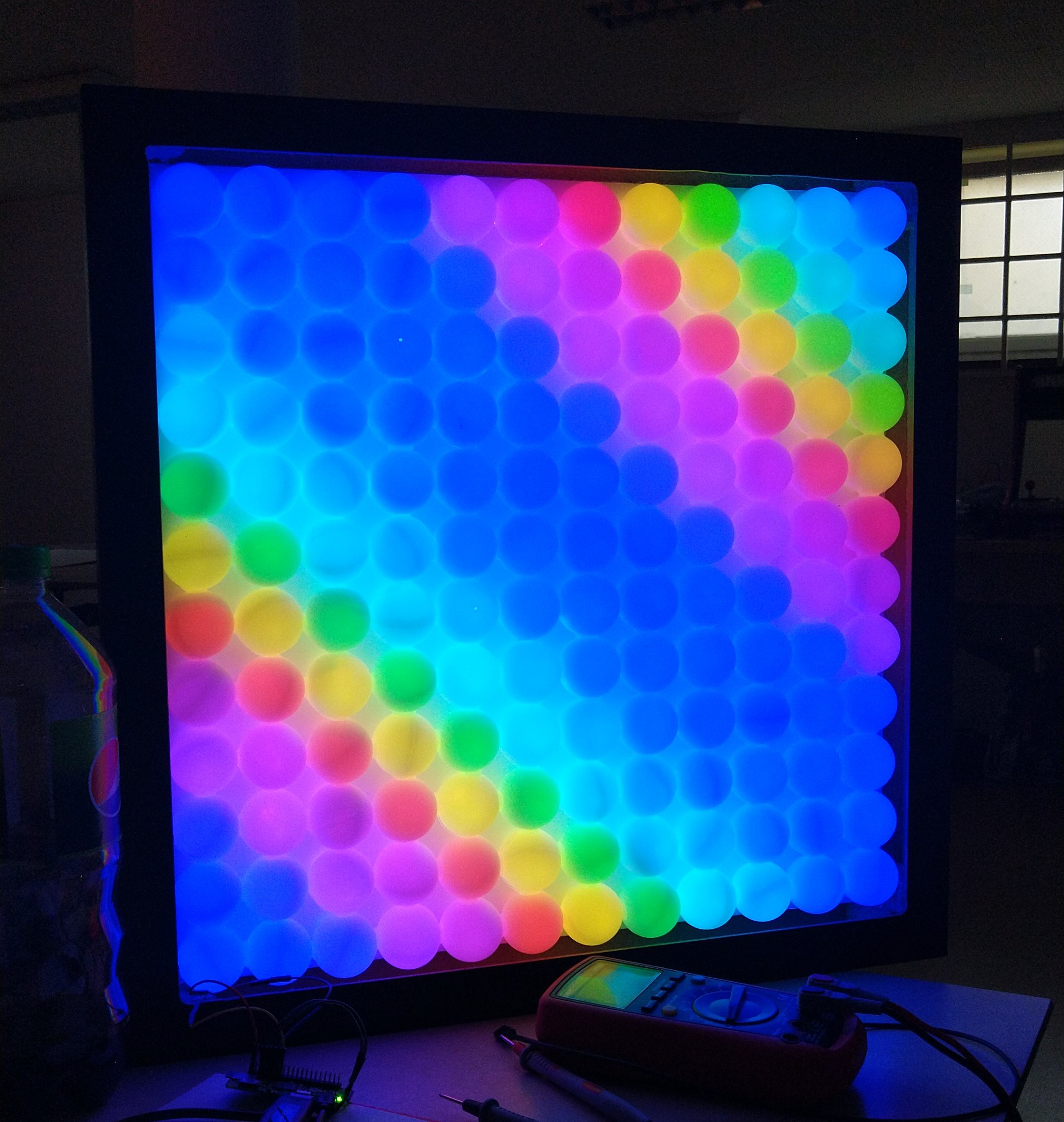
And here it is, the finished project! I'll let the photos speak for themselves.


Lastly, here's a video showing it in action, but note that it's really hard to capture bright LEDs on video so what you see is not 100% what you get, it looks even more gorgeous in person!
Discussions
Become a Hackaday.io Member
Create an account to leave a comment. Already have an account? Log In.
Awesome!!!
Are you sure? yes | no
2.0 perhaps? ;-)
Are you sure? yes | no
It is quite stunningly mesmerizing, or should I say "psychedelic".
I wonder what it would look like if the white back board were to be painted flat black. I think it would give even greater contrast. Wheels are turning...
Are you sure? yes | no
Yes I thought about that too after assembling the thing. Unfortunately the foam board fused with the balls when I made the holes in them so would need a new set of balls for that.
Are you sure? yes | no