Sponsor Link:
UTSource.net Reviews
It is a trustworthy website for ordering electronic components with cheap price and excellent quality.
Powering up this module
To power up this module for all of its function to completely work, you will need to make sure you have a stable +12 volt power supply and the CR1220 battery (as provided with this module). Then, make sure you follow the steps, as well as the images below: 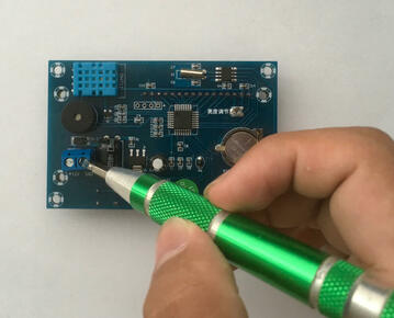 1. Flip the module onto its back side (screen facing down) and make sure the terminal screws are not tightened by rotating the screws anti-clockwise, as seen by the image above. You will need a flat head screwdriver to unscrew the terminal screws.
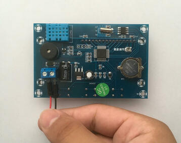 2. Insert your +12v (+) wire into the left terminal as marked by the labels on the PCB (printed circuit board). Then, for the right side of the terminal block, insert your GND (-) connection. Make sure the power going through the wires isn't active yet as it can be a shorting hazard when inserting it in.
 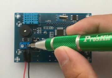 3. Once the wires are inside the terminal blocks, use a flat head screwdriver to tighten the screws on top of each terminal block by rotating the screws clockwise, and once that is done, make sure the wires are not able to be released easily.
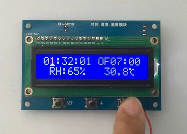
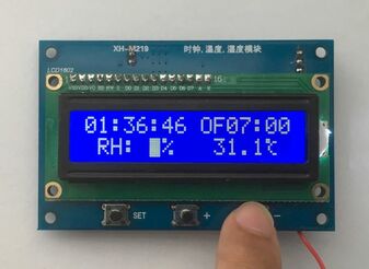
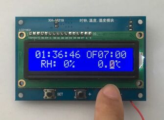
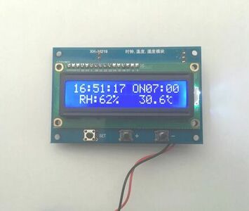 4. Now, you can flip the module onto its front side, turn the power through the wires on, and you will be able to see the LCD light up with all of the data on it (a picture of what is on the screen is above), thus indicating that the module has successfully powered up!
Changing the LCD contrast
Mainly depending on your environment's lighting conditions and whether this module is in an outdoor or indoor area, you may need to adjust the display contrast to your own preference. This alteration may greatly improve your view of the information displayed, and the screen from different perspectives. This can be done easily with the following steps below: 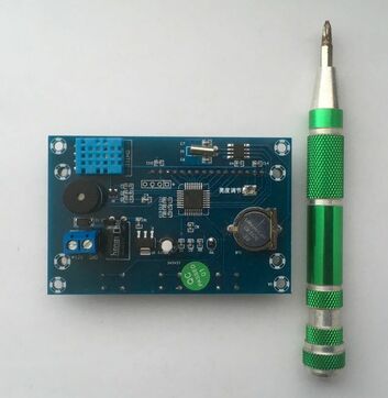 1. Flip the module onto its back side (with the display facing down) and make sure you have a Phillips head screwdriver with you, as seen in the image above.
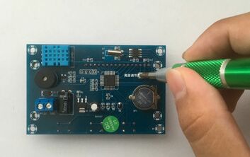 2. You will find a small screw implanted onto the back of this PCB (right above the battery) which you can adjust with your Phillips head screwdriver, depending on whether you want to increase the contrast or decrease the contrast. Rotate the screw clockwise or anti-clockwise in slight intervals to play around with this function and to really find the perfect contrast. I recommend turning the screw slightly every time, then glancing back at the display to see the change with every turn you make, until you have an ideal contrast level.
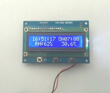 3. Once you have done that, flip the module back onto its front side (display side up) and you will see the display adjusted to your contrast changes.
Configuring the time
To configure the time on this clock module, it is fairly simple, where a few simple button clicks can do the job to allocate the correct time. Plus, after you have set the time you want, the button battery which you have placed in the back of this module beforehand, can remember the desired time for many months, or even years. If you try to turn the clock module off and on again, the time will still be remembered due to the CR1220 battery still powering the RTC (real time clock) chip, the DS1302. However, to set the right time first, please follow these steps below:  1. After you have powered the module on, press the "SET" button and you will see the the hour numerical figure blink, with an underline on the figure.
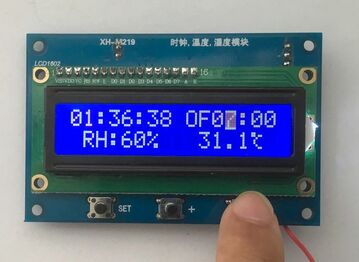
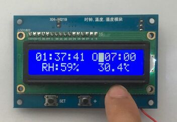
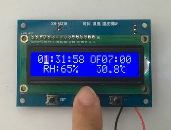
 2. From there, you can use the "+" and "-" buttons to cycle through the 24-hour numerical values from 00 to 24 hours, depending on the timezone you are in to set the correct time.
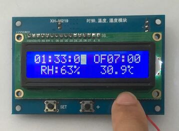
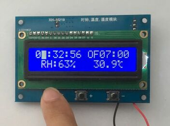 3. After you have set the correct hour, you would want to set the minutes and you can do this by pressing the "SET" button again directly after you have set the hours and the underline plus the flashing figure will move over to the minute figure.
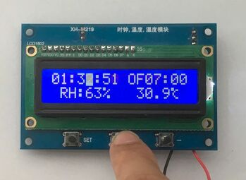
 4. Then, use the use the "+" or "-" button to cycle through the numerical values from 00 to 60 minutes. If you didn't press the "SET" button directly after setting the hours, the blinking value and the underline on the display will reset, so you won't see it anymore, but it can be fixed by pressing the "SET" button again until you have reached the designated value to change.
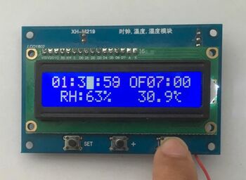
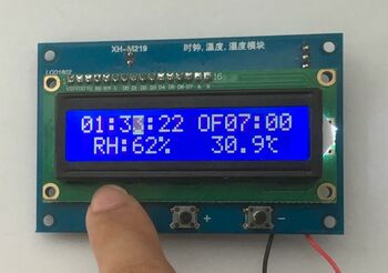 5. Next up, you will want to set the seconds correctly and by pressing the "SET" button once more after the underline and the blinking numerical value is on the minutes will set you up onto the seconds value, where you can cycle through the numerical values from 00 to 60 seconds. Again, if you just leave the "SET" button after setting a specific value, the blinking and underline on a value will reset and you will just have to press the "SET" button continuously until you the underline has switched to your designated value to change.
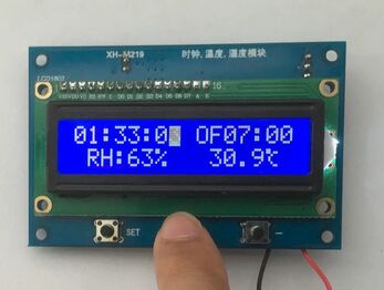
 6. Now, as you have done for the rest before, use the "+" and "-" buttons to cycle through the numerical values from 00 to 60 seconds to configure the seconds value of the time.
  7. After you have set the correct hours, minutes and seconds, you can just leave the buttons for a few seconds so that you will get out of the setting page and you will get back to the home page. Now, you have finished setting up the time!
Configuring the alarm
This module consists of a simple alarm function which you can configure, according to your own needs and this can be useful for many real-life applications, such as for a sleep timer or for a timing device. It takes a few steps to configure this alarm and you will know how to do it with these following steps: 1. Press the "SET" button 4 times until the underline and blinking lands on the "OFF" word.
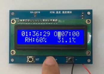
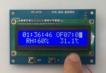
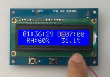 2. Once the underline lands on the "OFF" word and it is blinking, press the "+" or "-" button to change it to "ON" and this just turns on the alarm clock.
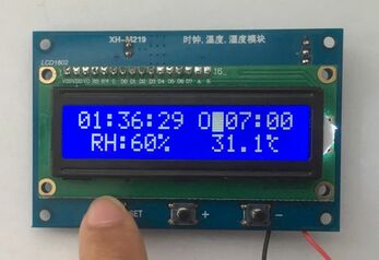 3. Press the "SET" button one more time and it will take you to the hour value of the alarm function.
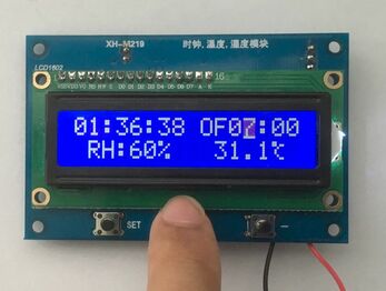
4. From here, you can use the "+" or "-" buttons to change the hour values from 00 to 24 hours of the alarm time you want to set.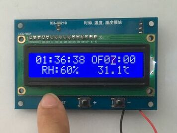 5. After altering the the hour values, press the "SET" button once again to land on the minute value of the alarm clock.
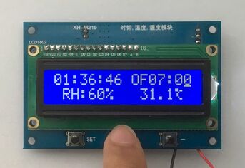
 6. Now, you can use the "+" or "-" buttons to change the minute values of the alarm clock from 00 to 60 minutes. Your alarm clock time is now set accordingly.
 7. You can now leave the buttons as it is for a few seconds and you will go from the setting page to the home page on the display.
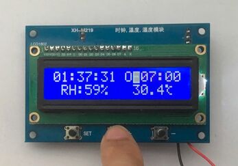
 8. When the alarm clock time has been passed, the on-board buzzer will start beeping continuously until any button on the module has been pressed. This will reset the timer to beep the next time that set time has past. Turn the alarm clock to "OFF" if you do not want the alarm function to be active anymore.
Configuring the relative humidity reading
With this multi-function module having an on-board DHT11 humidity sensor mounted onto its PCB (printed circuit board), there will obviously be a slight error value and uncertainty as nothing in the world of electronics can be 100% perfect. However, users of this module can get through this issue by configuring the humidity measurement manually by setting the error value from the current measurement to the right measurement with the following steps: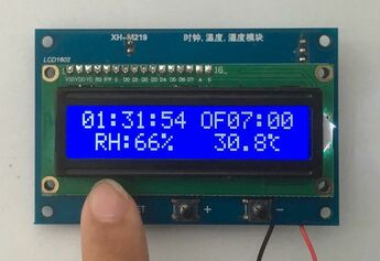 1. Press the "SET" button 7 times from the main home page until the underline and blinking lands on the relative humidity value. You will see 0% as the starting value to increase or decrease the error value from.
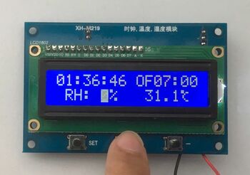
 2. Use the "+" or "-" buttons to either increase or decrease the error value in percent to suit your own needs, depending on the difference there is between your module's measurements and the actual ambient measurement.
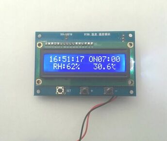 3. Once you have set the correct uncertainty or error value to the relative humidity measurement, leave the buttons alone for a few seconds to get the module out of its setting page and back to its home page. Your relative humidity measurement calibration should be all set now correctly and you should be able to see the changes to your measurement!
Configuring the temperature reading
Even though the XH-M219 module consists of an on-board thermostat (temperature detection probe) to capture the ambient temperature readings, there still is a slight uncertainty to its measurements, and if you wish to calibrate this temperature reading to your own preference, these are the steps which you can take: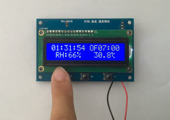 1. Press the "SET" button 8 times from the home page until the underline and the blinking digit reaches the temperature value. The temperature value will also reset to 0 once you are on it.
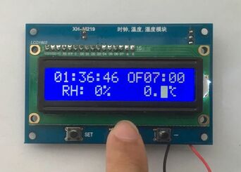
 2. Now, you can use the "+" or "-" buttons to set the uncertainty or error value depending on the difference between your own measurement and the ambient temperature measurement. This will then calibrate your temperature reading accordingly.
 3. Once you have set the correct uncertainty or error value to the temperature measurement, leave the buttons alone for a few seconds to get the module out of its setting page and back to its home page. Your temperature measurement configuration and calibration should be all set now correctly and you should be able to see the temperature measurement changes you have implemented!
Resetting the module
After you have configured and calibrated the various functions throughout this module, you may want to reset the entire module's memory back to its factory settings. However, to save you time, you would not have to manually go through each setting and set it back to normal, as you can simply press a few keys to reset this module completely by following these few steps: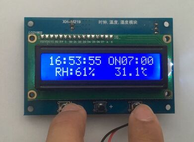
 1. Simply hold down the "SET" button and the "-" button simultaneously for five seconds to restore factory settings to the module. You will then see the measurements and alarm all reset back, where you will have to manually configure the time, alarm and sensory measurements again.
Conclusion
After going through the various functions all built-in to this module, I'm sure you will realise that this module is actually a perfect, little device for everyday use around the house, or in your car, and I feel like this is perfect for someone trying to tinker with electronics more. There are many basic sensors and components on-board this module and it seems like it is fairly simple to try to take this module apart or to even program it, with a little bit of software knowledge. However, what I really like about this module is the fact that it consists of so many combinations of hardware (sensors) and software (programming) in a single module, which is built so compact and simple to use. All in all, this was very nicely produced by our friends at ICStation and I would definitely take this in place of an ordinary clock!
Amazing opportunities
Also, be sure to check out PCBWay, a leading manufacturer and distributor in PCB design and manufacturing. They have amazing prices and excellent quality in their services, so don't miss out on them! Plus, PCBWay has an amazing website, online Gerber viewer function and a gift shop so make sure to check out their links below:
PCBWay Free Online Gerber Viewer Function: https://www.pcbway.com/project/OnlineGerberViewer.html
PCBWay Gift Shop: https://www.pcbway.com/projects/gifts.html
Make sure you check out the review for this product by clicking here.
Enjoy! Contact us for any inquiries!