 hesam.moshiri
Disclaimer: This circuit is connected directly to the mains voltage. You must care about all safety precautions before using the device.
AC loads are everywhere around us because at least home appliances are supplied with the mains power. Therefore, we always face the situations that we want to have full control (dimming) over an AC load such as a lamp, a motor, vacuum cleaner … etc.
We should know that controlling an AC load is not identical with a DC load. So we should use different electronic circuits for this purpose.
The figure-1 shows the mains sinusoidal wave with the frequency of 50Hz (sometimes 60Hz). To build a dimmer, the zero crossing points (the points where the wave changes its polarity) are important. To grab these points, we have to use a zero crossing detector. The figure-2 demonstrates the schematic diagram of the whole circuit.

Figure-1, Mains sine wave (Green arrows show the zero crossing points)
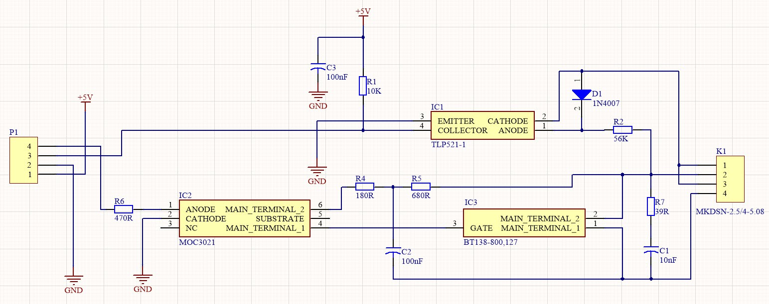
Figure-2, Schematic diagram of the digital AC dimmer
-
R1, R2, IC1 [1], D1, and C3 build the zero crossing detector circuit. It is designed to make proper isolation (optically) with the mains voltage. So we can expect to get a noise-free signal which can be safely connected to the Arduino I/Os. The figure-3 demonstrates the zero-crossing detector output signal (Pin-4 of the IC1). According to the TLP521-1 datasheet: “The TOSHIBA TLP521-1, -2 and -4 consist of a phototransistor optically coupled to a gallium arsenide infrared emitting diode.” For sure you can use similar optocouplers as well, but I use this part for other designs as well and it does the job quite well.
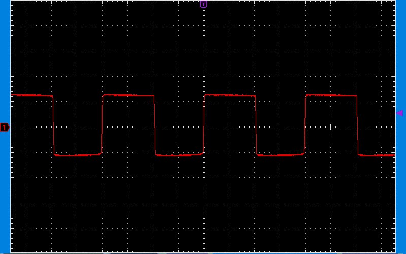
Figure-3, The output signal of the zero crossing detector circuit
-
So as it is clear, we gonna use the zero crossing pulse as a trigger for the main controlling circuit. Exactly after a trigger (a zero cross), in a simple term, we have to decide how much power we want to deliver. It is easier to understand by demonstrating the Arduino code and output wave later.
IC3 is a BT138 [2] Triac. The load is in series with the Triac and the AC line, so the Triac determine the amount of power that should be delivered to the load. According to the BT138 datasheet: “Planar passivated four quadrant Triac in a SOT78 (TO-220AB) plastic package intended for use in applications requiring high bidirectional transient and blocking voltage capability and high thermal cycling performance. Typical applications include motor control, industrial and domestic lighting, heating and static switching.”
Attention: the mounting base of the BT138 Triac (by default it is used to attach a heatsink) is connected to the Pin-2. It means you should never touch the heatsink or screw it to a metal enclosure!
R4, R5, and C2 implement a snubber circuit [3] for the IC2 and C1 and R7 make a snubber circuit [3] for IC3. These parts help the device to be compatible with a variety of loads, such as inductive loads.
IC2 is an Opto-Triac component which makes proper galvanic isolation between the digital side and the AC line. The selected part number is MOC3021 [4]. You can use similar part numbers also, but be careful not to use the parts with embedded zero crossing detector. Those parts are useful for switching the AC loads (ON/OFF), not for dimming.
I did not have the footprint and schematic symbols of the IC1, IC2, and IC3. So instead of designing the libraries from scratch and wasting the time, I used the free SamacSys Altium Designer plugin to install the libraries directly in the document [5] [6] [7]. The figure-4 shows the selected parts in the plugin’s UI.
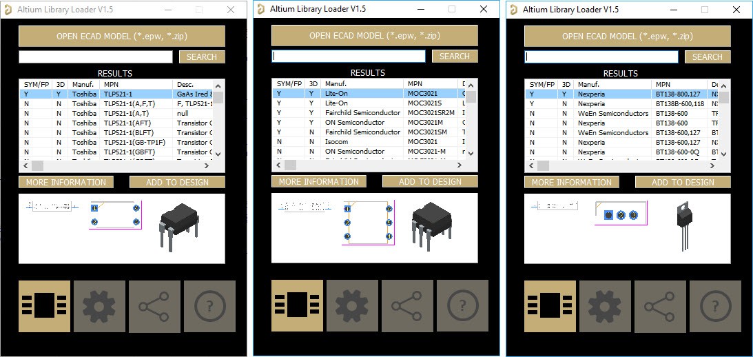
Figure-4, The selected schematic symbol and footprint libraries for IC1, IC2, and IC3
-
The figure-5 shows the designed PCB layout. The AC lines which are supposed to carry a high amount of current have drawn thicker and double sided. In addition, both track sides have reinforced by some Vias to reduce the resistance and increase...
Read more »


 ElectroBoy
 adria.junyent-ferre
 Sagar 001
Hmm, is mid cycle switch on a good idea for inductive loads? Have you tested it on motors?