 Mark Omo
The frontend (input) divider of an oscilloscope is one of the most critical components of the whole system. It needs to attenuate the incoming signal a precise amount over a very wide frequency range; in the case of the Probe-Scope, from 1 Hz to 50 MHz or more. This requires careful consideration of the parasitics on the PCB.
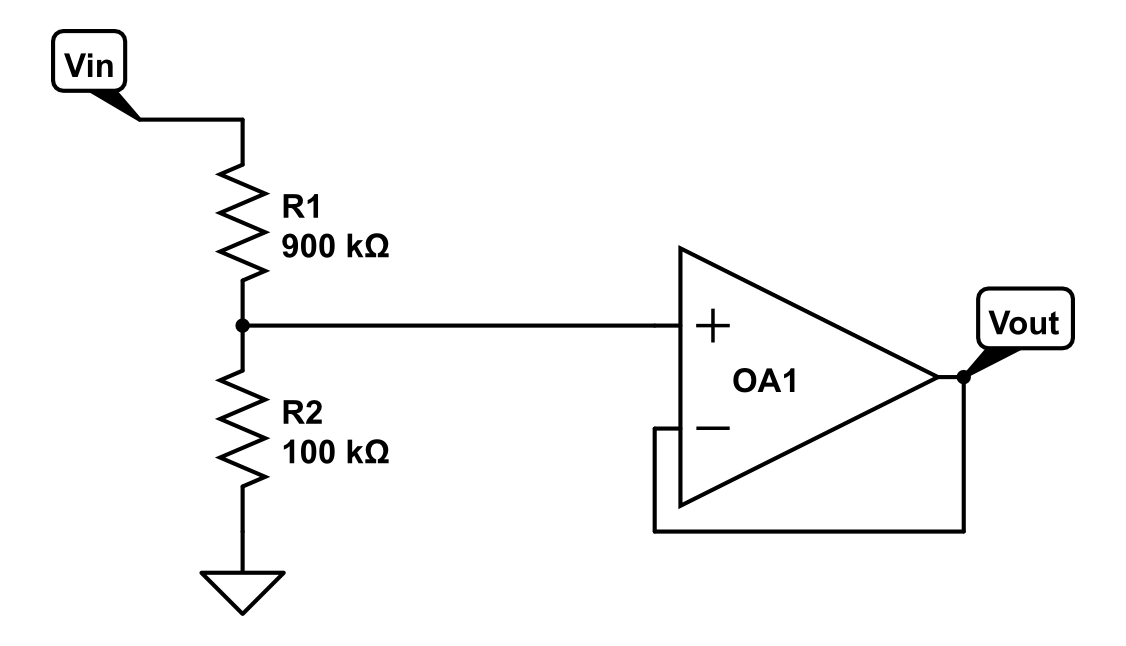
First, it’s important to know what an ideal frontend looks like. It’s a resistive divider with a buffer, with a constant divide ratio vs. frequency:
However, in the real world, things are not as simple as they might seem. Every component has what are called “parasitics”, i.e. parasitic resistance, capacitance, and/or inductance: these are the result of unwanted interactions between elements. In the case of our divider, parasitic capacitance has the largest effect on the system. The first major contributor is the capacitance of the op-amp’s non-inverting input. We are using the Analog Devices AD8055 for our buffer, which has a typical Input Capacitance of 2pF. The effect of this capacitance on the circuit can be drawn in the schematic:

The next elements that contribute capacitance are the resistors themselves. The pads on the PCB that they sit on form parasitic plate capacitors with the ground plane below:
The formula for a plate capacitor is C=(k ϵ0 A)/d. Because the size of each pad is 700μm by 800μm, assuming a standard PCB thickness of 1.6mm, as well as a dielectric constant of 4.2, that gives each pad around ((4.2)(ϵ0)(0.56mm^2))/1.6mm=13fF of capacitance. Here’s what those look like in the schematic:
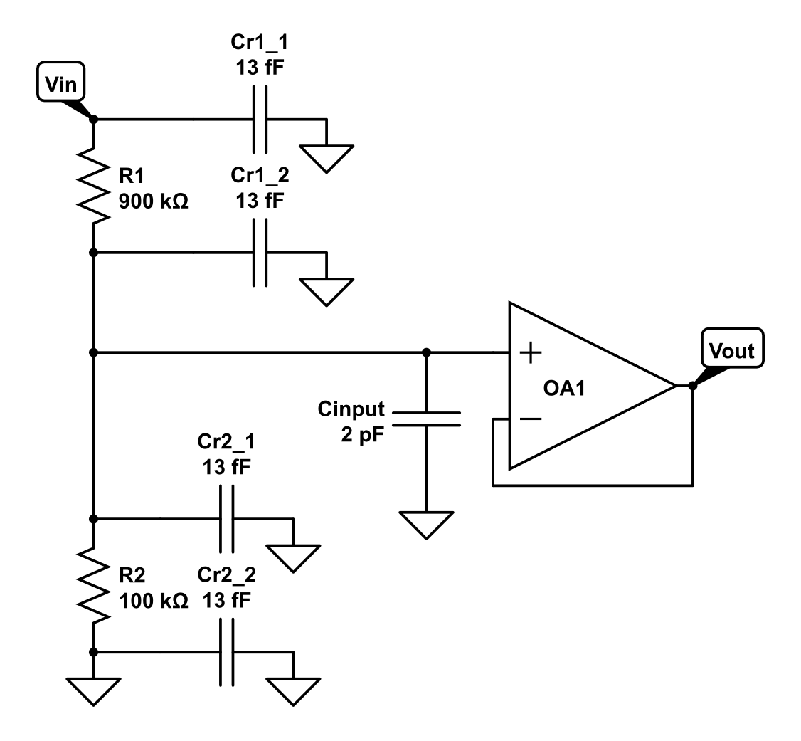
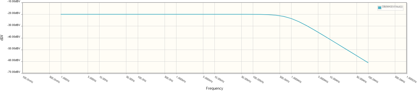
If we analyze the frequency response of that circuit, it’s clear that it won’t work for our target bandwidth of 50MHz. The parasitic capacitors form a low pass filter with the resistors, giving the front end a response that’s far from ideal:
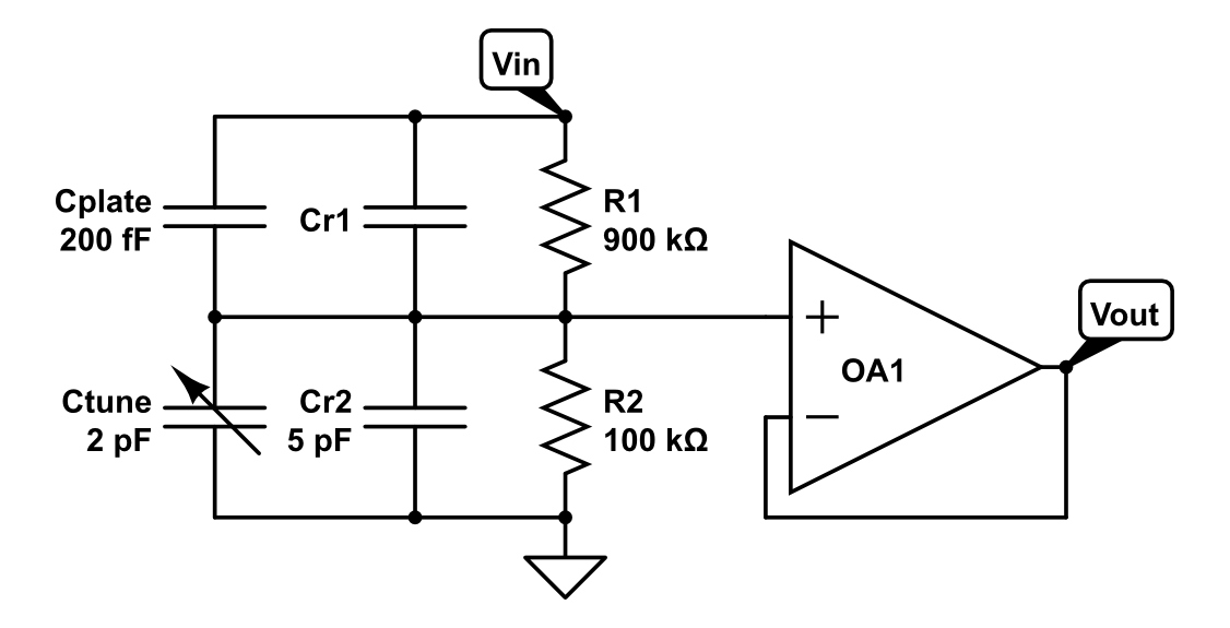
So, since that doesn’t get the system where it needs to be, we need to compensate for it somehow. If we simplify the system, we see that there are two critical values, the capacitance across R1 and across R2 (where CR1 includes other parasitics, putting its value is in the 0.1pF range):

For the divider to have the same ratio for all, frequencies C_R1 needs to be one tenth the value of C_R2, which means it needs to about 0.5pF. Because the parasitics are not well controlled we need to add a tuning cap, but there’s a problem: tuning caps in the 0.5pF range are VERY expensive (in the $20+ range), while inexpensive turning caps start in the 2pF range. To accommodate an affordable tuning cap, CR2 would need to be in the 20pF range, however that would result in the whole frontend having a high capacitance.
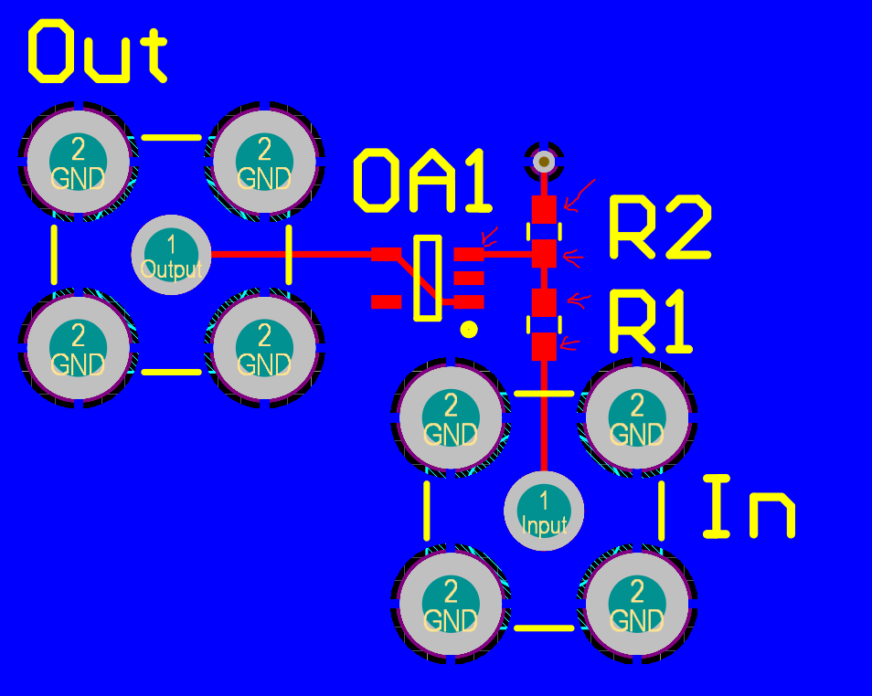
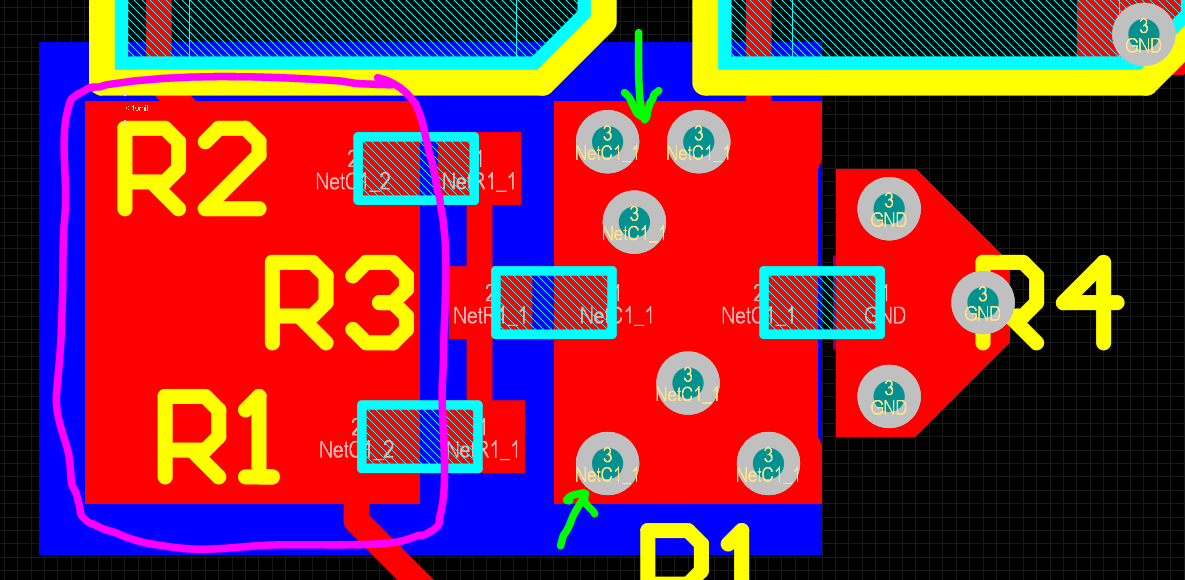
Instead, we can intentionally add some parasitic capacitance to R1 and add a 2pF tuning capacitor to R2. This will give us the desired response and a small input capacitance, without driving up the cost. We achieve this by extending the node between R1 and R2 as a plane on the bottom of the PCB, and placing another plane above it that’s connected to the top of R1 (Vin). Below is a screenshot of the layout of the Probe-Scope input divider, where R1, R2, and R3 form the top resistor (R1 in the schematic, it ends up being a weird value hence the multiple standard resistors) and R4 forms the bottom (R2 in the schematic). The area circled in pink is the top plate of the parasitic capacitor, and the green arrows indicate the vias that connect the divider node to the bottom plate of the capacitor.
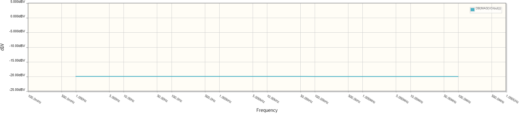
Here’s what our model looks like now:
And with all that in place, here’s our ideal frequency response!
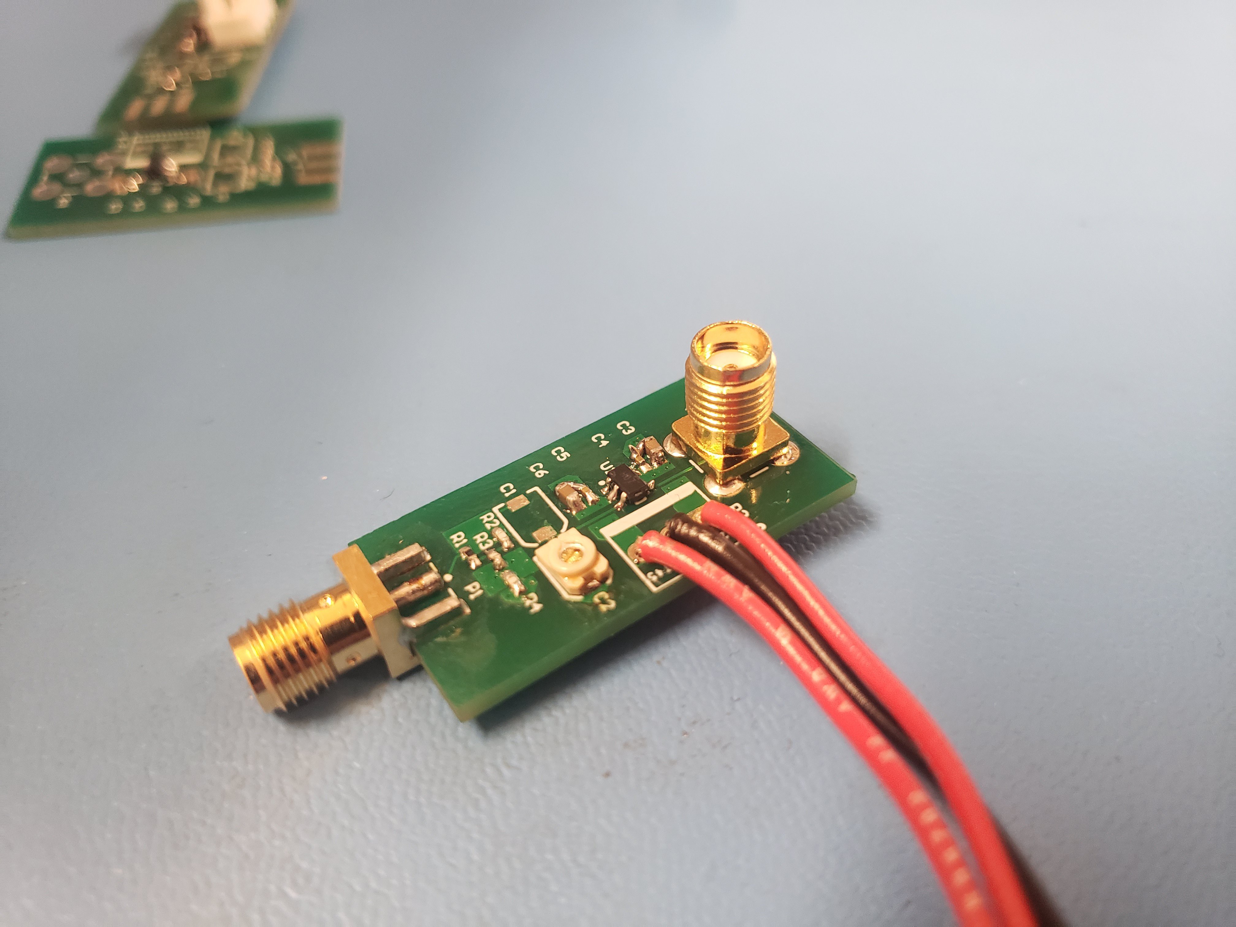
We elected to put the frontend divider on its own PCB for the first round of prototypes, rather than integrating it with the rest of the frontend so we can test each component independently.
Here’s a picture of the board, it's slightly more complex than the example presented above. A detailed post about the frontend performance will come shortly!
Discussions
Become a Hackaday.io Member
Create an account to leave a comment. Already have an account? Log In.