 Mark Omo
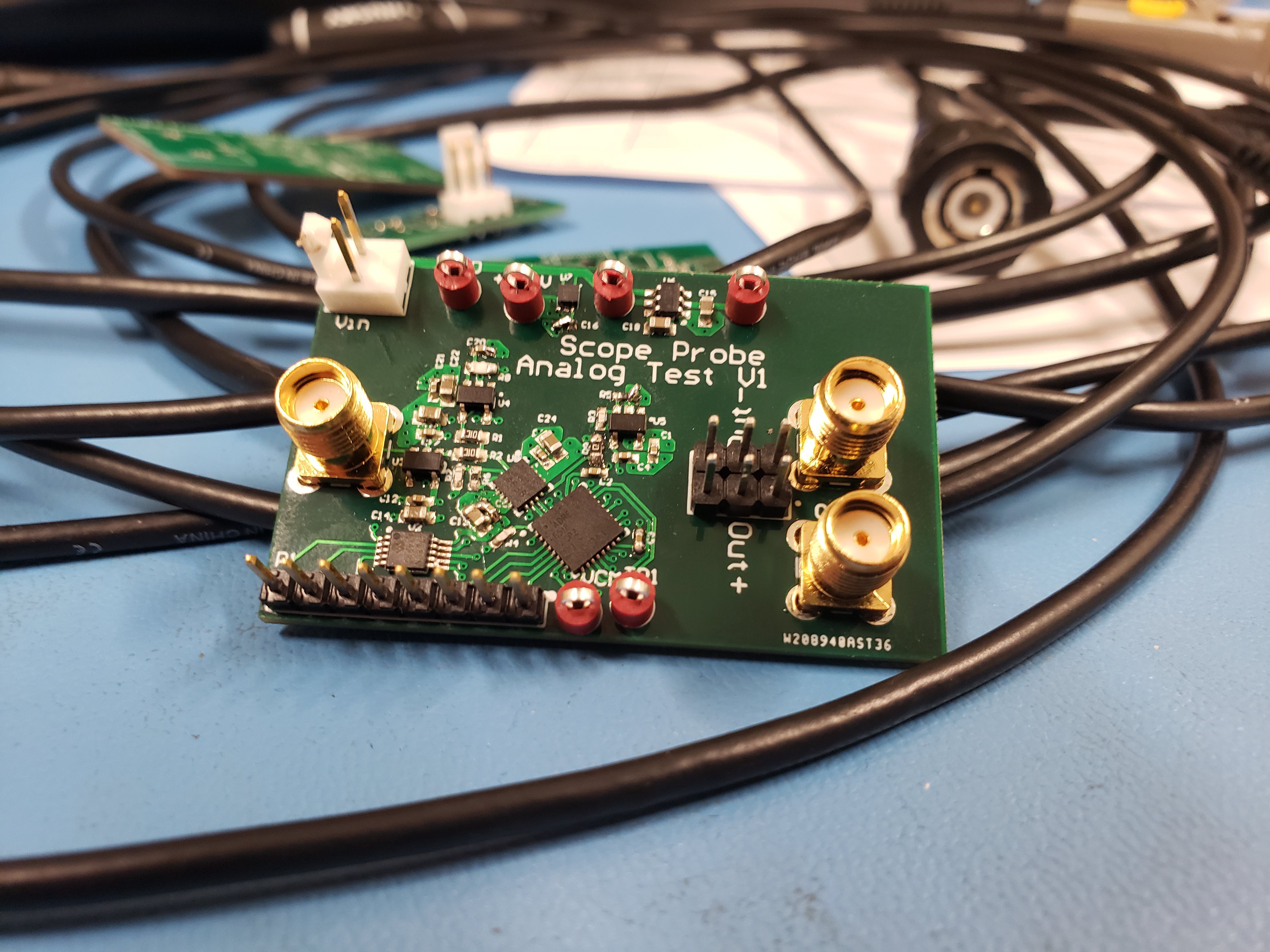
Having recently received the parts and PCBs for all of our subsystem test boards, this post is one in a series detailing the buildup and testing of those boards. Today we’ll be showing off our Analog Frontend board, which includes the Variable Gain Amplifier (VGA) and Filter that makes the whole thing work. To start, here’s a picture of the finished board
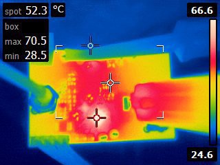
After cursing the designer of the board (me), who decided that 0402 was the right size for most of the components, I finally got it assembled and up and running. One of the first things that I noticed was that it ran hot. In the back of my mind, I knew that the VGA (an ADRF6518) drew a lot of power (400mA at 3.3V or around 1.3W), but I didn’t quite consider the thermal implications of that. Checking the board with a thermal camera (shown below), the VGA got all the way up to around 70°C, which is actually right about the calculated value, but of course, I forgot to calculate it beforehand…
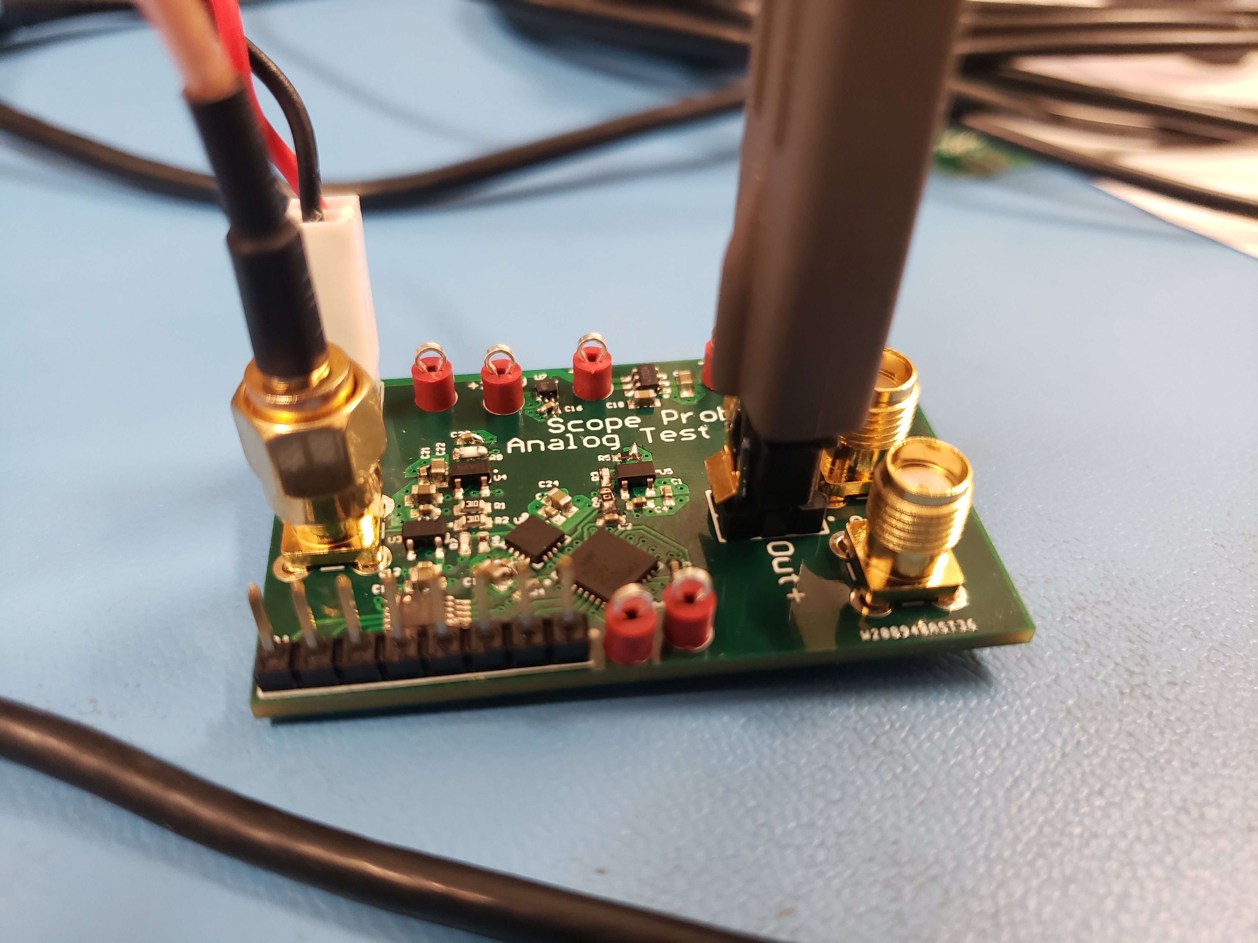
The first thing I did was write some Python scripts for my Raspberry Pi to control the ADRF6518 (over SPI), letting me play with its bandwidth and gain settings, along with controlling the MCP4728 DAC that set the Offset and Gain levels. Once I got it all set up and working, I connected it to our DG8SAQ VNA in order to get some frequency response plots, and they looked amazing! Here’s a picture of the board all hooked up for testing. I’m using a Tek P6248 differential probe (plugged in on the right) to feed the signal into the DG8SAQ.
Shown below is a screenshot of the results, with five sweeps at five different bandwidth settings, from 1MHz to 63MHz (the maximum setting).
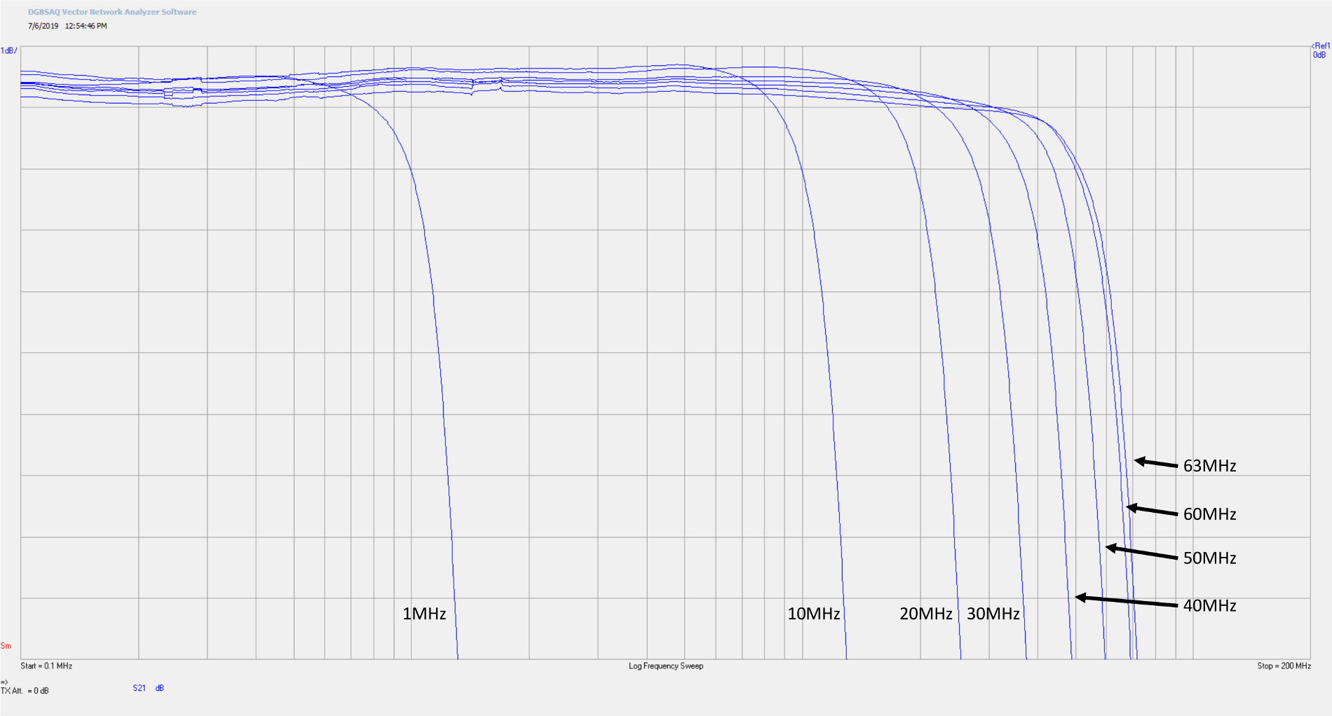
As you can see, the gain is flatter than 0.5dB overall, and for individual settings it’s better than 0.1dB. And now here’s a screenshot zoomed all the way out, with the bandwidth set at 50MHz. To achieve an ENOB of 8 bits, we need at least 50dB of rejection at our Nyquist frequency (125MHz) in order to prevent aliasing. Here we get 80dB of rejection, well beyond the requirement.
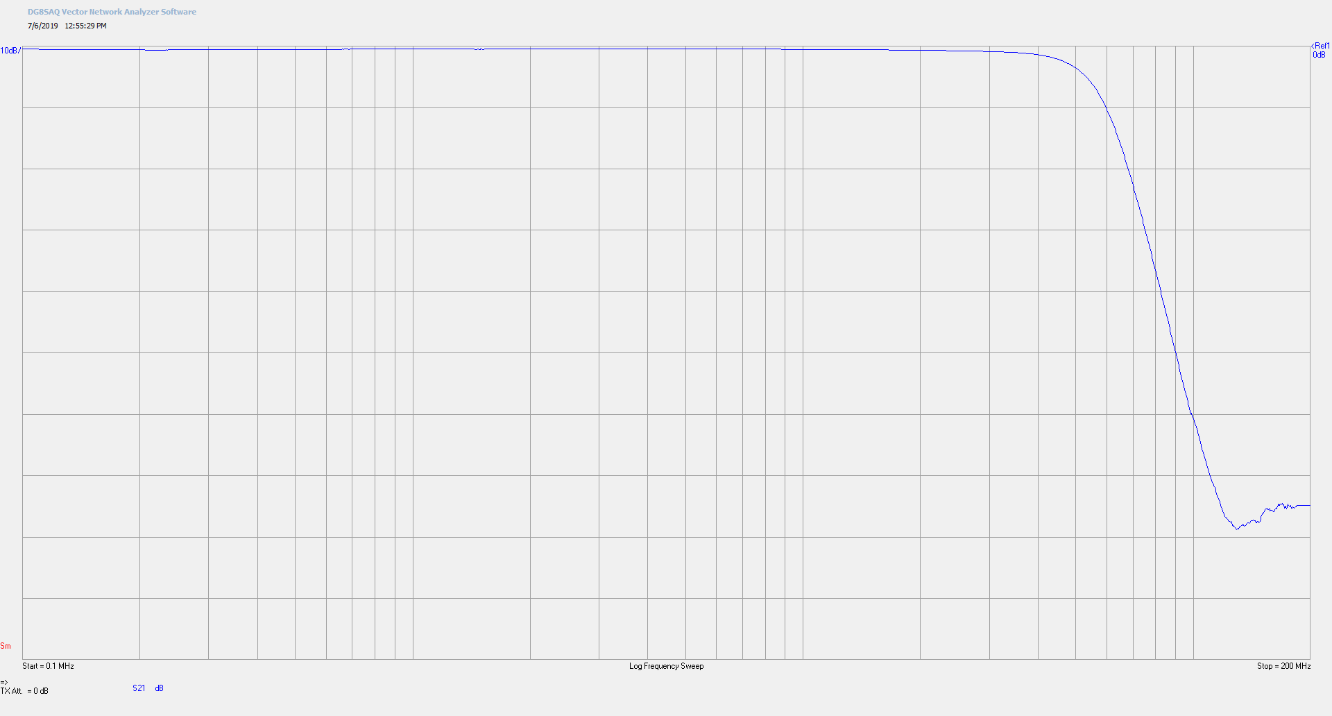
The frontend was working so well, in fact, that I decided to test it at 63MHz (the maximum frequency of our VGA Filter) and we were able to get 65dB of rejection! Therefore, we can comfortably rate the Probe-Scope’s maximum bandwidth as 63MHz, surpassing our design goal of 50MHz.
You can find the schematics and layout for this board on our GitHub, or if you go back to an older project log, there’s a screenshot of it too. Next on the list is the Digital Test Board, which we’ll have a short post about just verifying its hardware up soon.
Discussions
Become a Hackaday.io Member
Create an account to leave a comment. Already have an account? Log In.