 Tirdad sadri nejad
With that in mind, I began designing a simple dev-board. after a few trials and errors, the "Astra Avia" is born and :
- It has 3.3v, 5v and GND on both side of the board.
- It has an RGB LED connected to first three outputs of TIM3 PWM channels.
- The first three channels of hi-sink driver are the same as RGB LED. so you can visually monitor the PWM on the mentioned hi-sink outputs.
- All the extended features like the RGB and hi-sink driver are disconnectable through a solder-jumper. you can even disconnect one GND pin from the MCU and reserve it just for the driver alone to isolate noise.

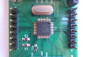
I designed the PCB in my labcenter proteus EDA and after some revisions, sent the final board to my local PCB fab (KaraPCB, iran). they sent me 10 free samples.
one of the complexities of a modern microcontrollers is, that they may multiplex a peripheral on more than one set of pre-defined GPIOs. so we get lost each time where to wire it. let alone the problem of remembering which led is connected to which pin of mcu. so I noted the pins with their functionality. e.g. H7A8 means hi-sink channel 7, and PA8 pin of mcu. A14WC and A13WD are SWCLK and SWDIO pins of SWD debug interface.
All done. it works perfectly and connects to STM32CubeProg through UART with no error.
After all, there are a few things which can be added for a future revision:
- A tiny lithium ion battery charger chip. LTC4054 would be a good choice.
- An integrated schottky diode for connecting external supply for ADC (VDDA pin). The VDDA line is already disconnectable from VDD through a solder-jumper on back of the board.
- An external crystal for microcontroller. (that big 12MHz crystal you see on the board is used for CH340 chip, not the MCU). F0XT and F1XT pins are marked for that reason.
- An easier to solder 5v line. As the 5v line is a single pin header at each side, it's a hassle to solder correctly.
 Stefan Lochbrunner
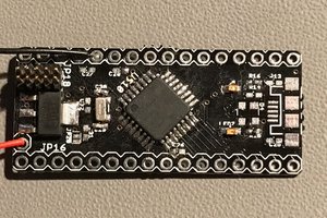
 SimonXi
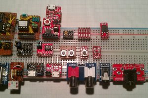
For double row pin headers i make "protoboard": https://hackaday.io/project/29527-protoboard-uni