 Alan Green
I'm going to need some way to mount all these components to my kitchen ceiling. The current plan is to have a base board to which to attach the components. I'll flip the base board upside-down, and mount the back side to the ceiling. I'll also need a lid for it all.
Laser and Galvo
The only really critical alignment required is between the laser and the galvo. I modelled them both in Fusion 360 and then laser cut a tiny prototype base plate to verify that I had the relative locations correct.

Both modules screw into the base plate, and there are two scraps of PCB under the laser module to raise it about 3mm.
I then modeled and printed a 3D table with a small back angle so that the laser galvo's center will be aimed at the center of the wall, rather than up near the ceiling. Here is the model:
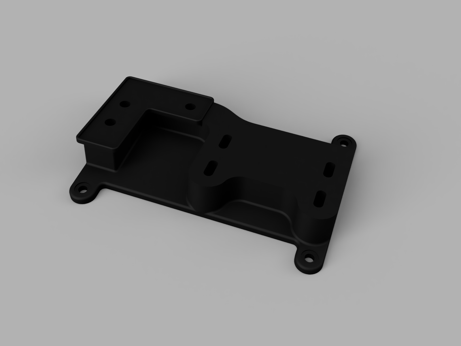
And it came out just like that, but not as pretty:

Despite the rough look, it feels fine in the hand and works exactly as required:
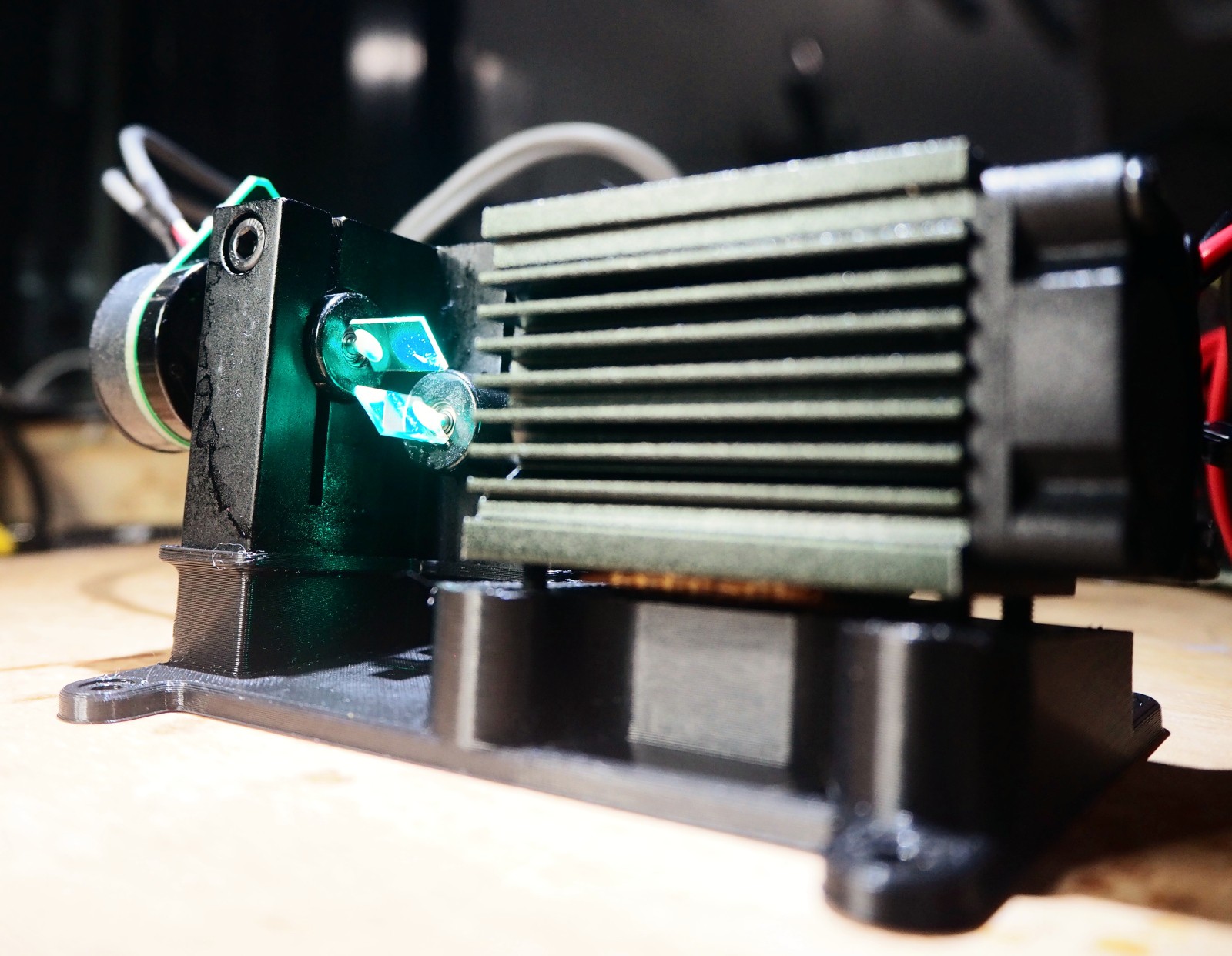
I'm not happy with every detail - it's taller and bulkier than it needs to be, the laser module part has a cut out on one side but not the other, and there's a weird join between the table for the module and the table for the galvo. All that said, it is the first 3D print I designed myself, and it will work just fine. It's a keeper.
A funny story for those of you who have read this far: I noticed that the laser was not hitting in the center of the mirrors. For the x-axis (lower) galvo, the light was partly on the blob of glue that holds the mirror. To fix this, I loosened the bolt that holds the galvo into the block and moved the galvo back a little. At this point I realized the galvo can not only move further in and out of the block, it can also rotate. Doh. I had spent a day modeling that table in order to move the Y axis by 6.8 degrees. I could have just rotated the galvo by 3.4 degrees.
The table is a better solution, but I don't know that it was worth the time.
Prototype Base Plate
I had a first attempt at a base plate. I modeled at least the outlines of each of the electronic components, then threw the whole lot onto a rectangular base. Here's what it looked like in Fusion 360:
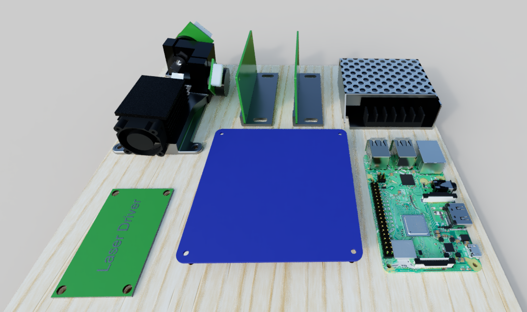
The Raspberry Pi is a model I found in Autodesk's library. It looks beautiful, with each cap, resistor, header pin and sheet metal fold individually modeled. However, it does push Fusion 360 quite hard. I think I should maybe just use the PCB in future layouts. The BlueBoard#01 in the middle has a decal in the model, but that decal just fails to appear in the render. No idea why.
And here it is on my bench:
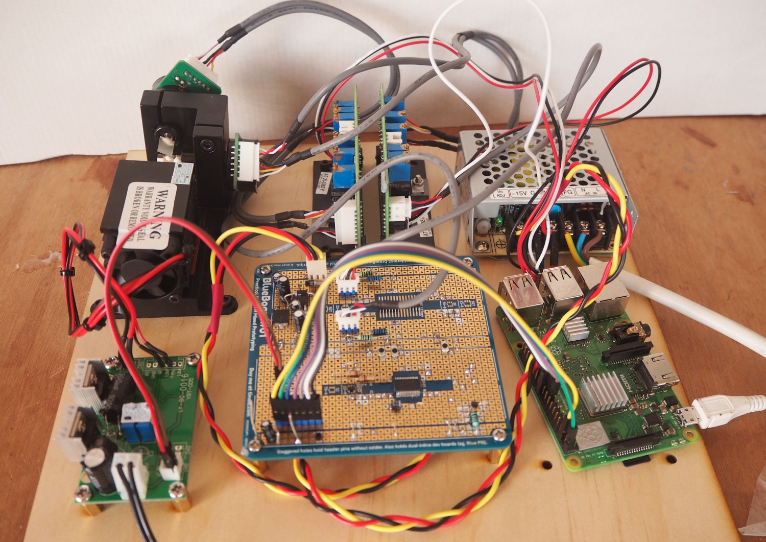
Mostly successful. The general layout is OK. I'll need some kind of cable management in the final version. The biggest issue was with mounting the RPi. It has M2.5 mounting holes, and I had eyeballed them as M3. According to the forums, it is possible to safely drill the holes out to M3, but I've ordered the M2.5 mounting hardware anyway.
It's early days. I will also need to mount a 4-way mains power board on this base board and make a transparent, openable lid. Oh yeah - also figure out how to attach it to the ceiling in some removable way.
Discussions
Become a Hackaday.io Member
Create an account to leave a comment. Already have an account? Log In.