Close
0%
0%

D1 Mini UI Shield

Add a user interface to a D1 mini

Similar projects worth following

Often you need some kind of a user interface for your project — a display, a menu, maybe some icons, some numbers or some plot, etc. Sure, you can simply slap a display module on it, but then you still need some kind of input. If your display comes with a touchscreen and you are ready to handle the complexity in code, then great. Otherwise you need to add a bunch of buttons, a joystick, an encoder or some other way of selecting options. And since at that point you have ran out of GPIO pins on your D1 Mini, you also need some kind of GPIO expander. And then you have to put it in some box to attach the buttons to, and it all gets complicated quickly.

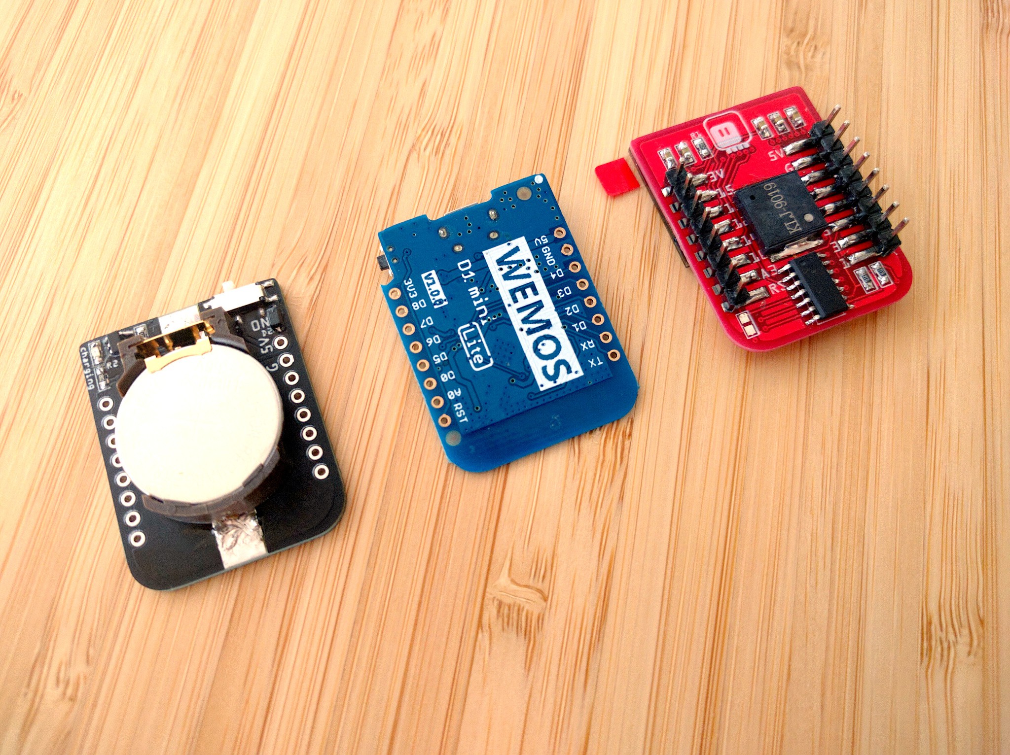
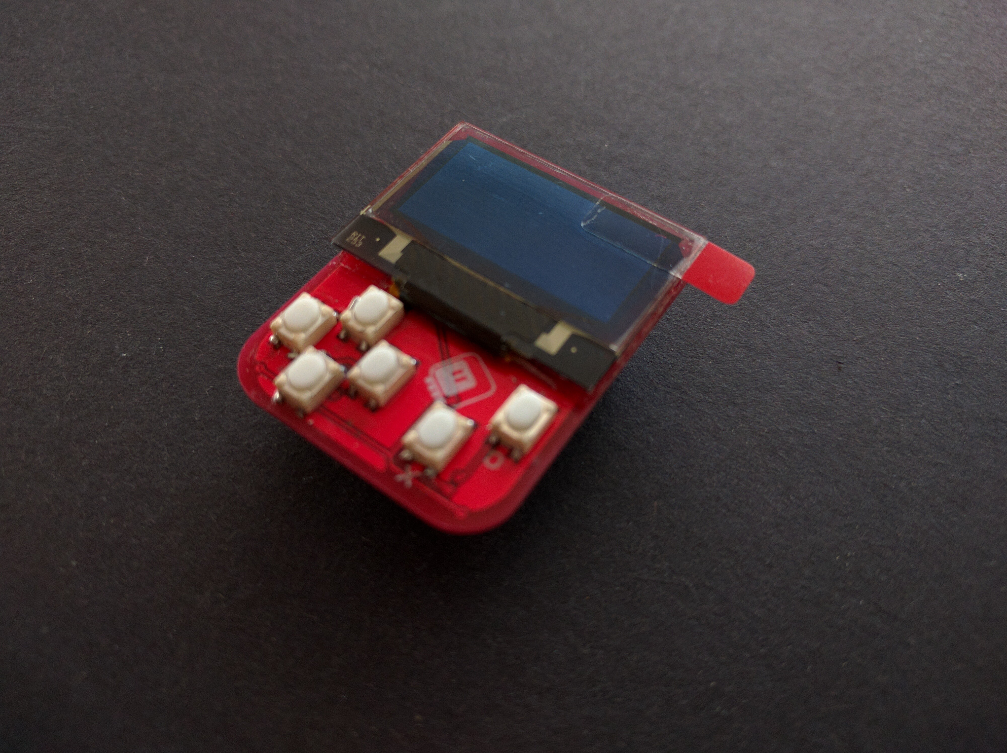
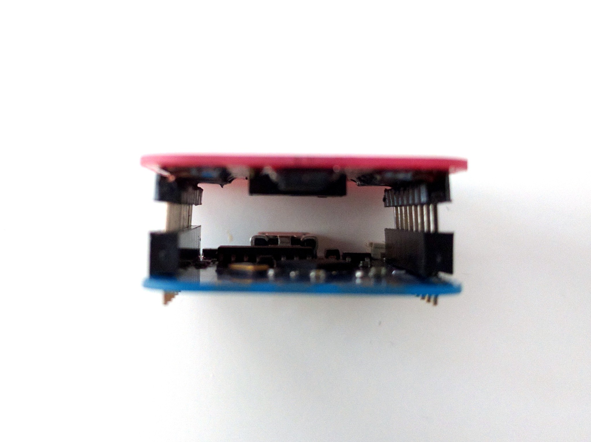
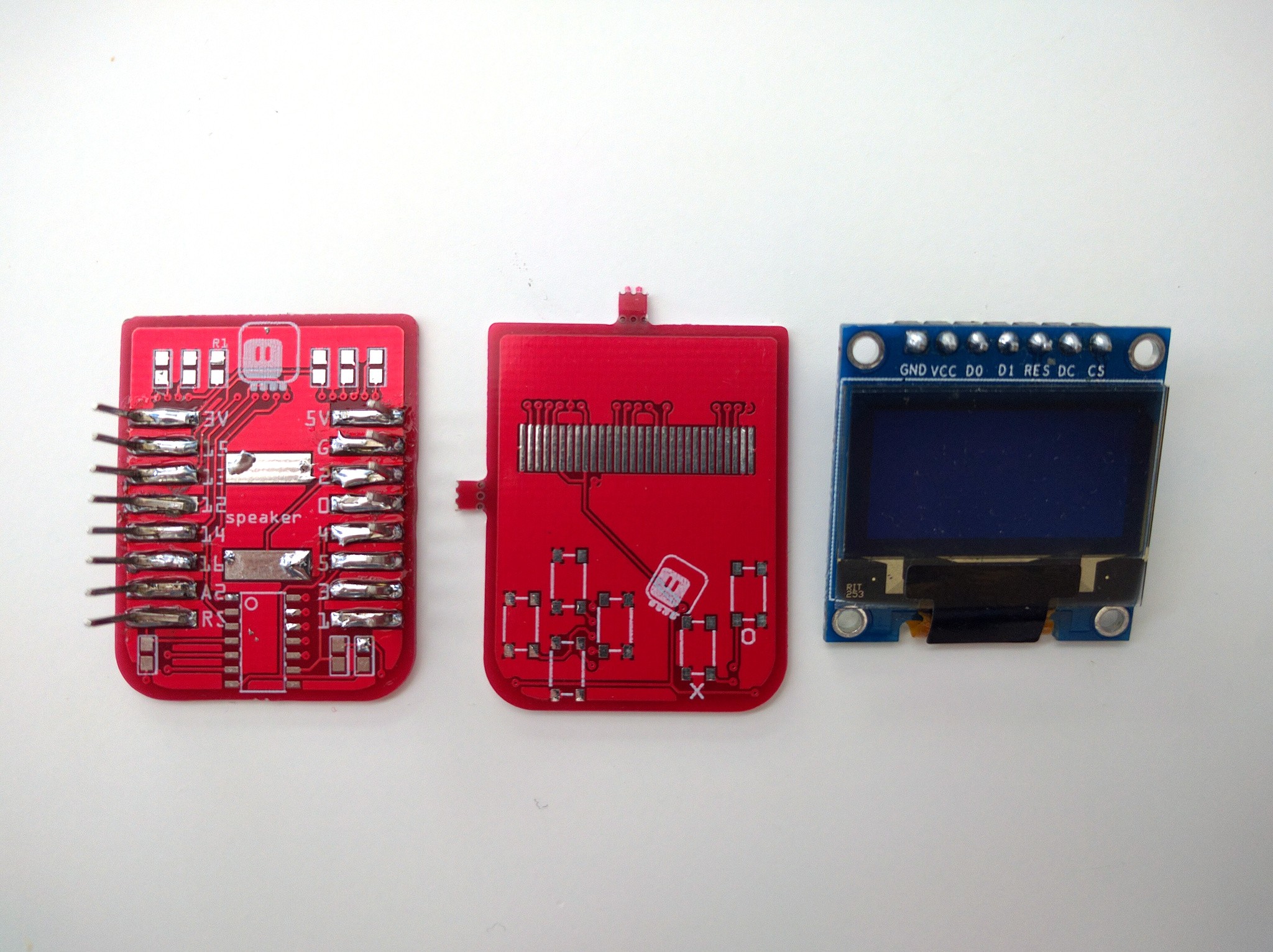
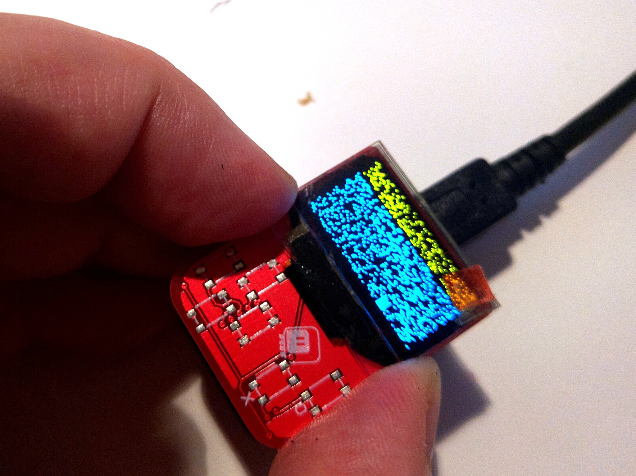
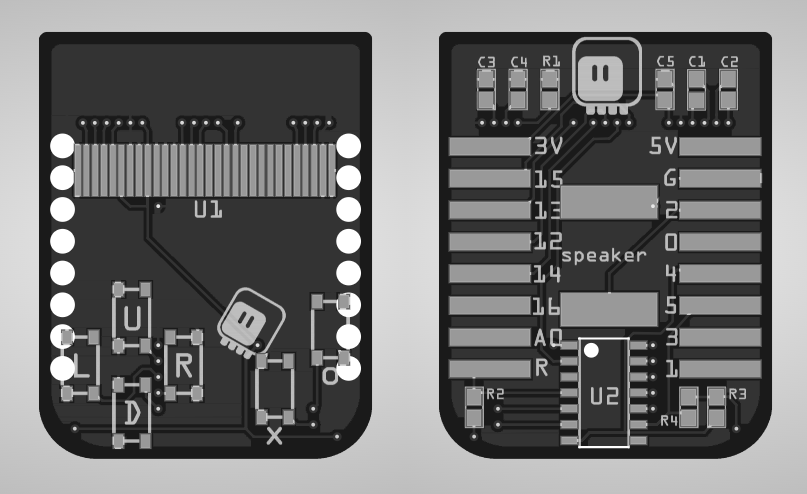
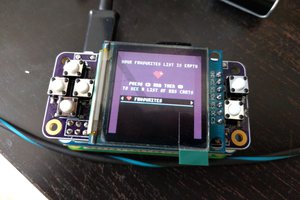
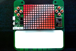
So this is a quick solution for that problem: basically an OLED display module and the #D1 Mini X-Pad Shield squeezed together on a single small shield. You can even play games on it, if you feel like that!

x-fritzing-fzz - 73.93 kB - 06/19/2019 at 19:56

Download

gerber.zip

gerbers

Zip Archive - 312.85 kB - 06/19/2019 at 19:56

Download

  • Battery

    deʃhipu07/04/2019 at 11:34 0 comments

    The UI shield and the D1 Mini Lite make together a very nice small device, but they lack power. That is why I revived my #Coin Battery Shield for D1 Mini project, and made a shield that fits on the back of the whole assembly, creating a pretty neat sandwich:

    And all together:

  • Tindie

    deʃhipu06/19/2019 at 19:55 0 comments

    This shield is now available on Tindie. Unfortunately, for now I only had one complete unit (because I only had two displays, and I need one prototype for, uh, prototyping), and it's already sold. But as soon as I get more displays (should take a week or two), I will put up more for sale. You can add it to a wishlist to get a notification.

    The price is a bit more than what I would like, but it's really a lot of work soldering, and I had to re-order many parts with faster shipping (because the ones I ordered with free shipping still didn't arrive after two months).

  • Buttons!

    deʃhipu06/19/2019 at 13:16 0 comments

    After re-ordering and choosing a faster shipping method, I finally have those tiny buttons:

    They are definitely better than those "reset" buttons I used on nGame, but still a bit on the hard side.  Also very clicky and with reasonable travel. The larger surface of the button itself makes a lot of difference.

    Soldering them is a bit hard — the contact pads are not large enough to hold the buttons down with surface tension, so the hot air gun just blows them away. So far the most efficient way is to just solder them by hand, with the soldering iron, going from left to right and adding the buttons as you go.

    Unfortunately, the 20 displays that I ordered (2x10pcs order) turned out to be 2 displays when they arrived (the seller admitted to a packaging error and refunded the difference), so I only have one prototype to play with and one unit for sale. More displays are on the way, though, so expect it on Tindie near you soon-ish.

  • More Details

    deʃhipu06/09/2019 at 18:15 0 comments

    I think I have perfected the technique of soldering those angled headers now — after assembling a few more.

    The speaker on GPIO02 makes some cool sounds on boot — because that's the debug serial output pin.

    For completeness, here is the firmware for the attiny24:

    #include "USI_TWI_Slave/USI_TWI_Slave.c"
    
    
    #define PINS_COUNT 6
    #define RST_PIN 10
    #define I2C_ADDRESS 0x10
    
    const uint8_t pins[PINS_COUNT] = {0, 1, 2, 3, 7, 8};
    volatile bool clear = false;
    volatile uint8_t buttons = 0;
    
    
    void request() {
        USI_TWI_Transmit_Byte(buttons);
        clear = true;
    }
    
    void setup() {
        pinMode(RST_PIN, OUTPUT);
        digitalWrite(RST_PIN, HIGH);
        for (uint8_t i = 0; i < PINS_COUNT; ++i) {
            pinMode(pins[i], INPUT_PULLUP);
        }
        USI_TWI_Slave_Initialise(I2C_ADDRESS);
        USI_TWI_On_Slave_Transmit = request;
        delay(50);
        digitalWrite(RST_PIN, LOW);
        delay(50);
        digitalWrite(RST_PIN, HIGH);
    }
    
    void loop() {
        static uint8_t last_buttons = 0;
        uint8_t current_buttons = 0;
    
        for (uint8_t i = 0; i < PINS_COUNT; ++i) {
            current_buttons <<= 1;
            current_buttons |= !digitalRead(pins[i]);
        }
        if (clear) {
            clear = false;
            buttons = 0;
        }
        buttons |= last_buttons & current_buttons;
        last_buttons = current_buttons;
        delay(16);
    }

    Nothing complicated, really — I'm using the USI example from the Atmel application note here, keeping everything in the main loop, so as to not block or delay the interrupts. 

    Lastly, I wonder if I should work on the thickness of the whole thing, or just stuff a lipo in there:

  • Assembly

    deʃhipu06/08/2019 at 11:20 0 comments

    A few weeks later, and the PCBs have arrived. Unfortunately they weren't matte-black, as I originally ordered from @Elecrow, because I have panelized them, and apparently that is not allowed with matter-black — but they had no problems when I asked to change the color to red.

    I tested how the angled headers as SMD pin headers work, and that was reasonably good:

    (I included a module with a 0.96" display that I'm going to use here, for scale.)

    The second attempt actually went much smoother, and I have a good technique of soldering them without too much work now, so I consider that experiment a success.

    Next, I programmed an attiny24, soldered it in place, soldered all the passives, and added a display that, for now, I just desoldered from some module (I have proper, white, displays on order). A quick MicroPython script to test the display:

    import machine
    
    spi = machine.SPI(1, baudrate=1000000)
    cs = machine.Pin(15, machine.Pin.OUT, value=1)
    dc = machine.Pin(12, machine.Pin.OUT, value=0)
    
    def write(data, command=True):
        cs(0)
        dc(not command)
        spi.write(data)
        cs(1)
    
    
    write(
        b'\xAE' # display enable = off
        b'\x8D\x14' # charge pump = enable
        b'\xAF' # display enable = on
        b'\x20\x02' # address mode = page
        b'\xB7' # page = 7
        b'\x00x\x12' # column = 32
    )
    
    write(
        b'\xFF\x0F\xFF\x0F\xff\x0f\xff',
        False
    )
    

    and several hours to fiddling with the passives and connections, until I figured out that the flex cable in the display I have is broken and only works in a certain position:

    But at least I confirmed that the display is working.

    I'm still waiting for the buttons to arrive — it's been two months already, since I ordered them for #PewPew Mini — but I hope they will arrive Really Soon Now™. 

  • The PCB Design

    deʃhipu06/08/2019 at 11:07 0 comments

    This project actually started a looong time ago, back when I was still playing with #D1 Mini Matrix Deluxe Shields, #PewPew FeatherWing was starting to take shape in my head, and nobody even dreamed about #µGame. I was inspired by the D1 Mini OLED shield, but I wanted some buttons on it, and I wanted them to be arranged in a d-pad. Then other projects happened, and I forgot about it, until recently, when I started to play with those OLED displays again, and found my old designs. Having learned a lot in that time, and having found some new really tiny buttons, I decided to revive this project and e-design it. I came up with this PCB design:

    As mentioned in the description, it's basically the #D1 Mini X-Pad Shield compressed to a smaller size (and with two of the buttons removed), and with a display added on top. I used one of the free pins for the display's reset (it has to be reset after powering on, and I didn't want to waste the ESP8266 pin for that), but otherwise it's the same.

    I had a moment of doubt when choosing how to connect the display: it supports both I2C and SPI modes. In the end I decided to use SPI, even though the buttons already use I2C. That is because SPI is faster and supported in hardware by the ESP8266 (I2C is bit-banged).

    Another challenge was fitting the 0.96" display and buttons on top of the shield, without them conflicting with the pins. In the end, I decided to use the same technique I used in the #Gesture FeatherWing — angled pin headers soldered as SMD to the PCB, only this time I made them a bit shorter too.

    In the end I had some free space in the middle, so I decided to put a buzzer in there, so you can even have sounds.

View all 6 project logs

Enjoy this project?

Share

Discussions

Makerfabs wrote 07/01/2019 at 08:20 point

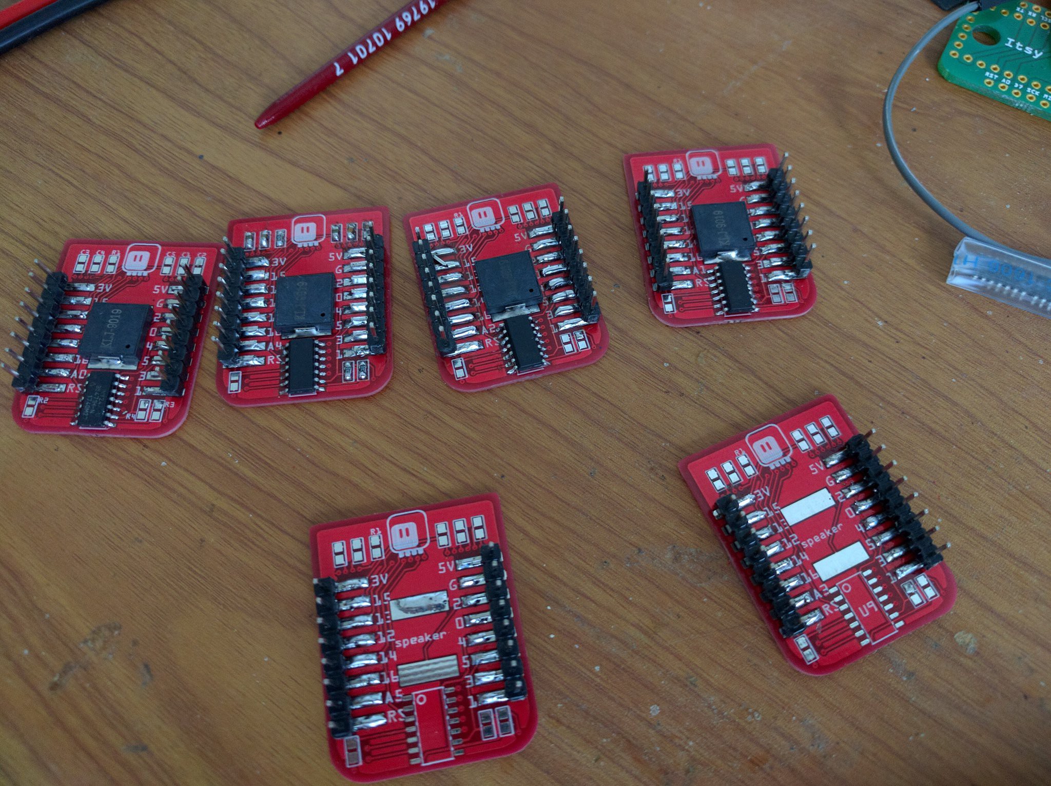
...maybe you need an expert, for the items and soldering....:)  good luck//

  Are you sure? yes | no

deʃhipu wrote 07/01/2019 at 10:56 point

Thanks. I don't think this one is a good candidate for fabrication, since I made so many hacks in there — it would be difficult to automate. I would need to redesign it to use real SMD headers and so on.

  Are you sure? yes | no

Similar Projects

Does this project spark your interest?

Become a member to follow this project and never miss any updates