 deʃhipu
I think I have perfected the technique of soldering those angled headers now — after assembling a few more.
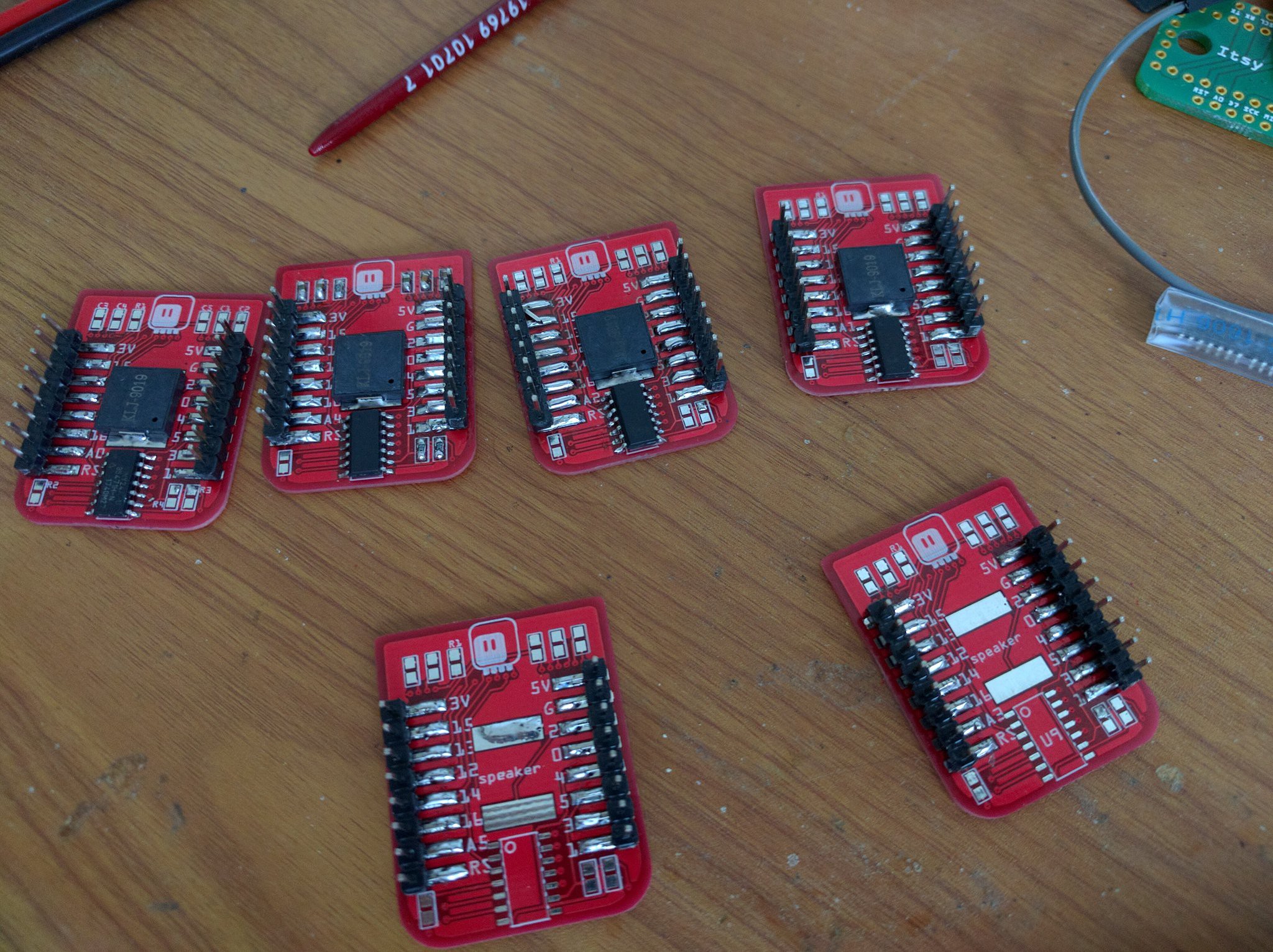
The speaker on GPIO02 makes some cool sounds on boot — because that's the debug serial output pin.
For completeness, here is the firmware for the attiny24:
#include "USI_TWI_Slave/USI_TWI_Slave.c"


#define PINS_COUNT 6
#define RST_PIN 10
#define I2C_ADDRESS 0x10

const uint8_t pins[PINS_COUNT] = {0, 1, 2, 3, 7, 8};
volatile bool clear = false;
volatile uint8_t buttons = 0;


void request() {
    USI_TWI_Transmit_Byte(buttons);
    clear = true;
}

void setup() {
    pinMode(RST_PIN, OUTPUT);
    digitalWrite(RST_PIN, HIGH);
    for (uint8_t i = 0; i < PINS_COUNT; ++i) {
        pinMode(pins[i], INPUT_PULLUP);
    }
    USI_TWI_Slave_Initialise(I2C_ADDRESS);
    USI_TWI_On_Slave_Transmit = request;
    delay(50);
    digitalWrite(RST_PIN, LOW);
    delay(50);
    digitalWrite(RST_PIN, HIGH);
}

void loop() {
    static uint8_t last_buttons = 0;
    uint8_t current_buttons = 0;

    for (uint8_t i = 0; i < PINS_COUNT; ++i) {
        current_buttons <<= 1;
        current_buttons |= !digitalRead(pins[i]);
    }
    if (clear) {
        clear = false;
        buttons = 0;
    }
    buttons |= last_buttons & current_buttons;
    last_buttons = current_buttons;
    delay(16);
}
Nothing complicated, really — I'm using the USI example from the Atmel application note here, keeping everything in the main loop, so as to not block or delay the interrupts.
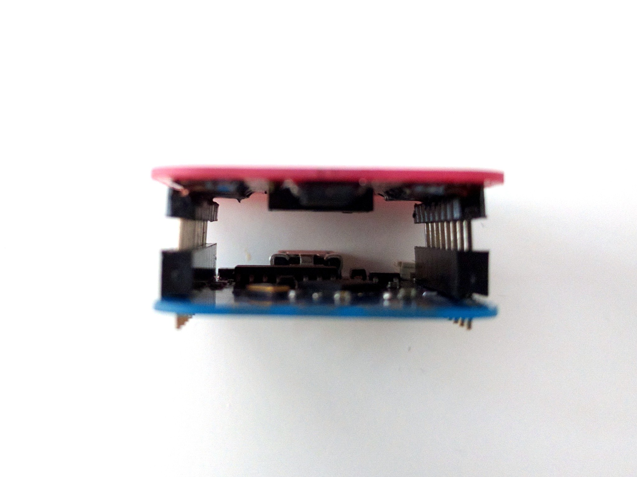
Lastly, I wonder if I should work on the thickness of the whole thing, or just stuff a lipo in there:
Discussions
Become a Hackaday.io Member
Create an account to leave a comment. Already have an account? Log In.