0%
0%
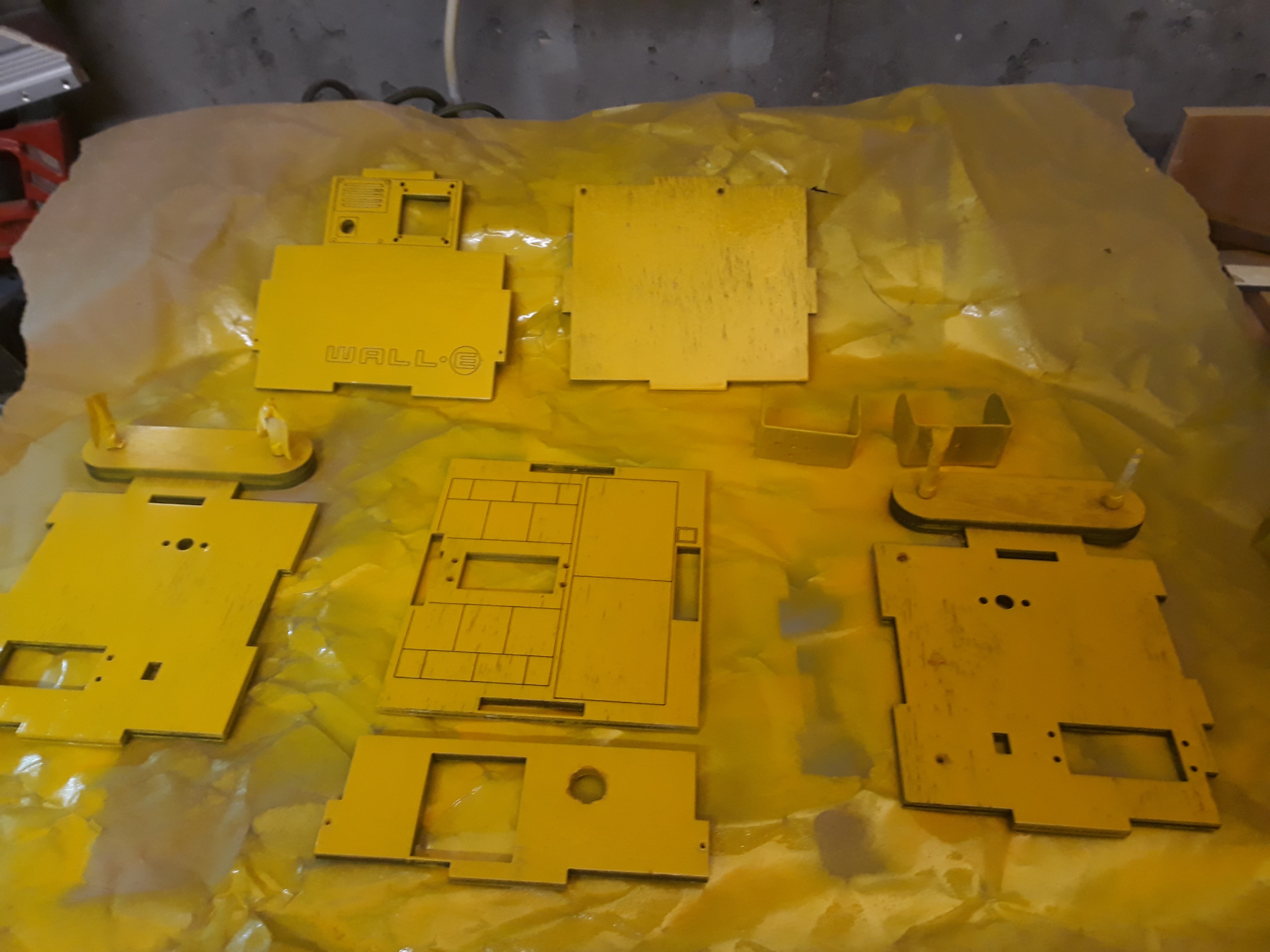
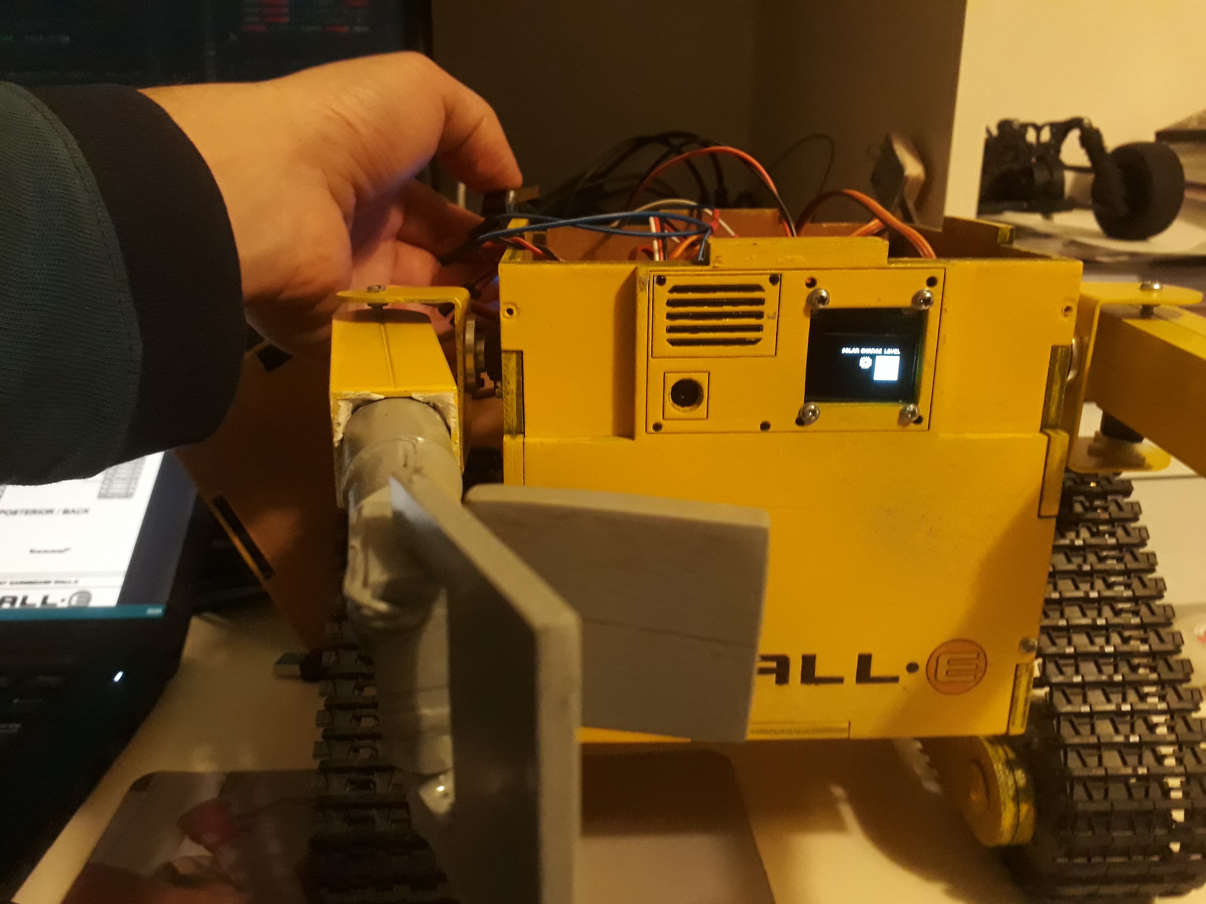
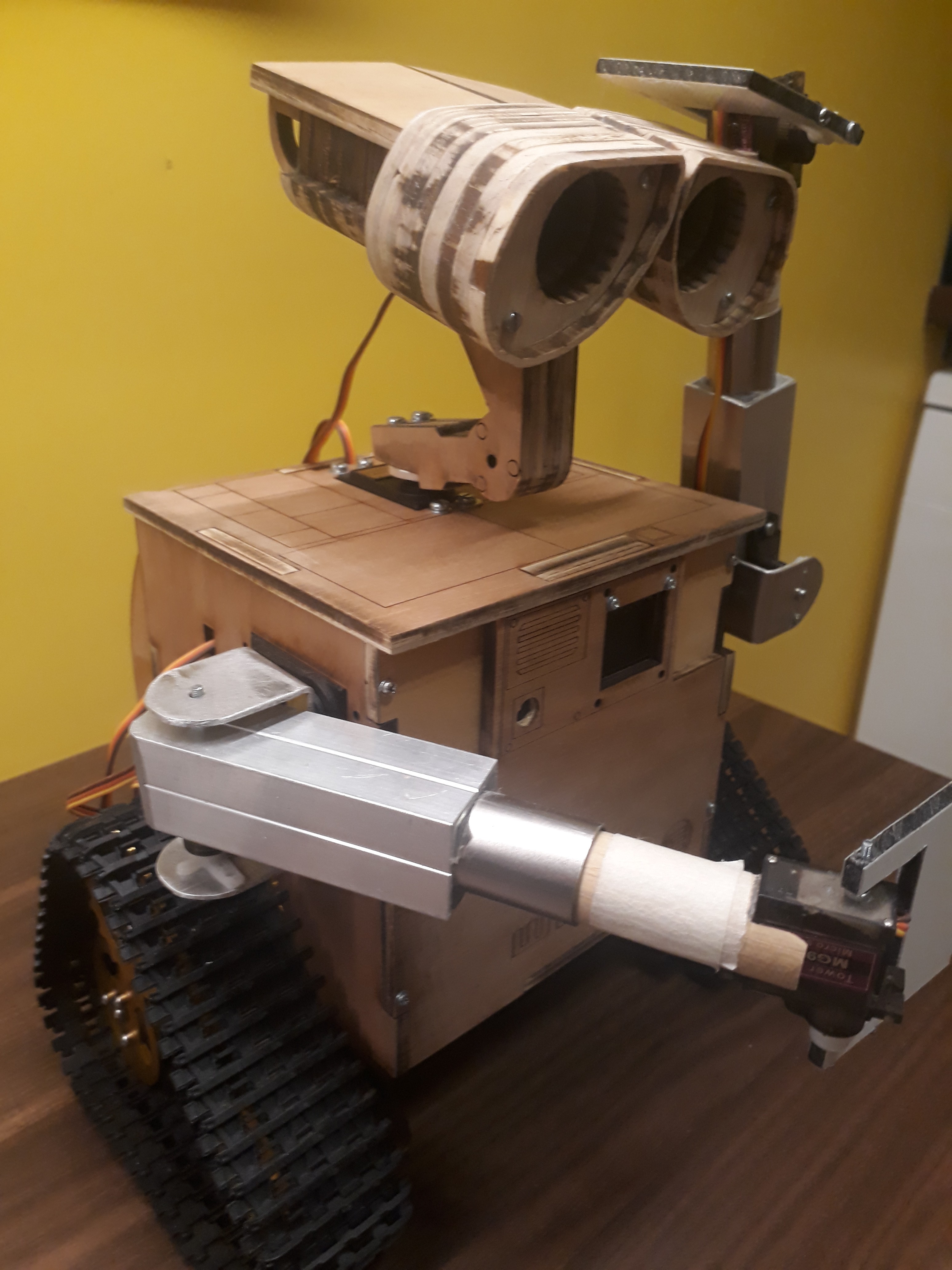
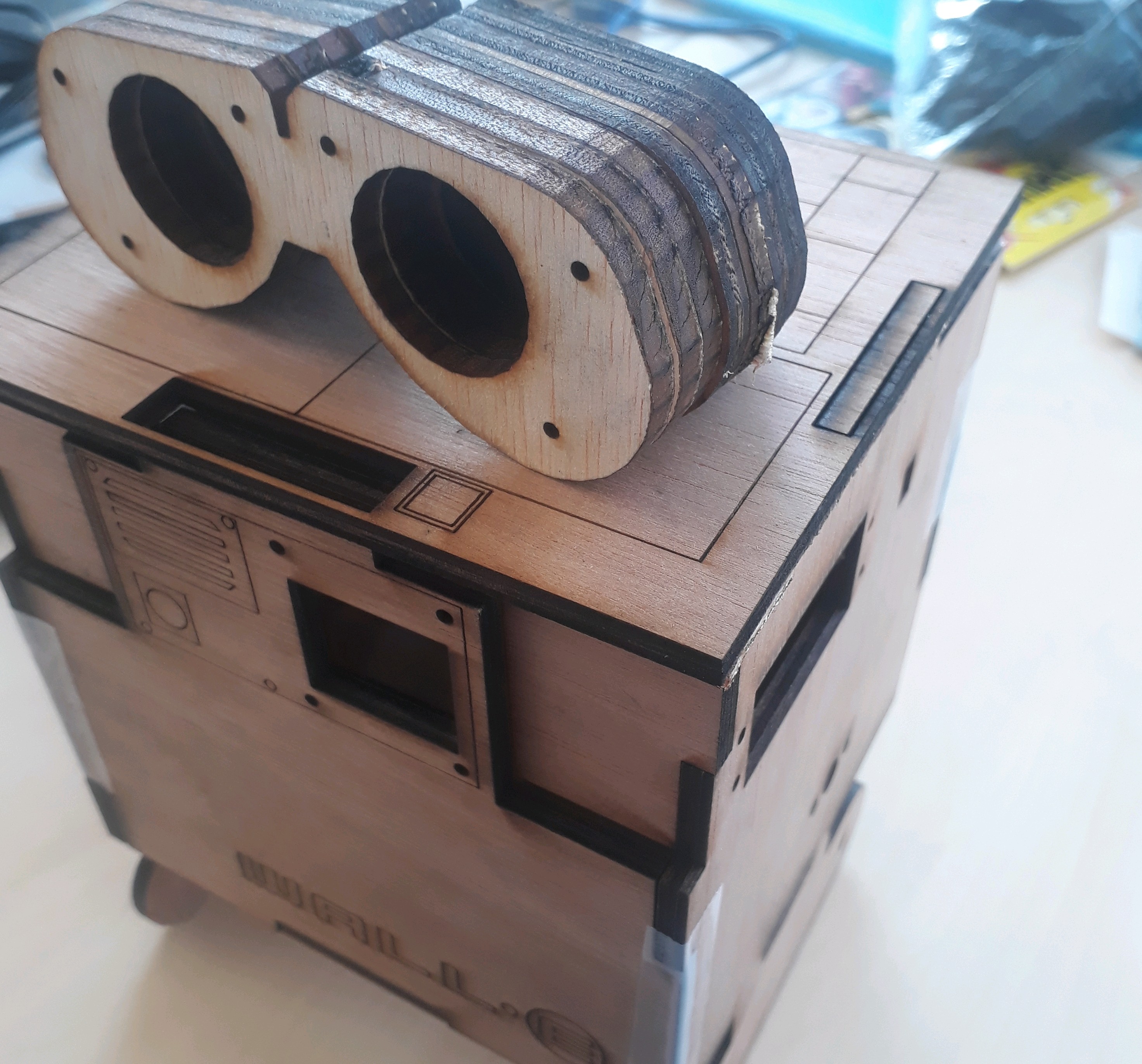
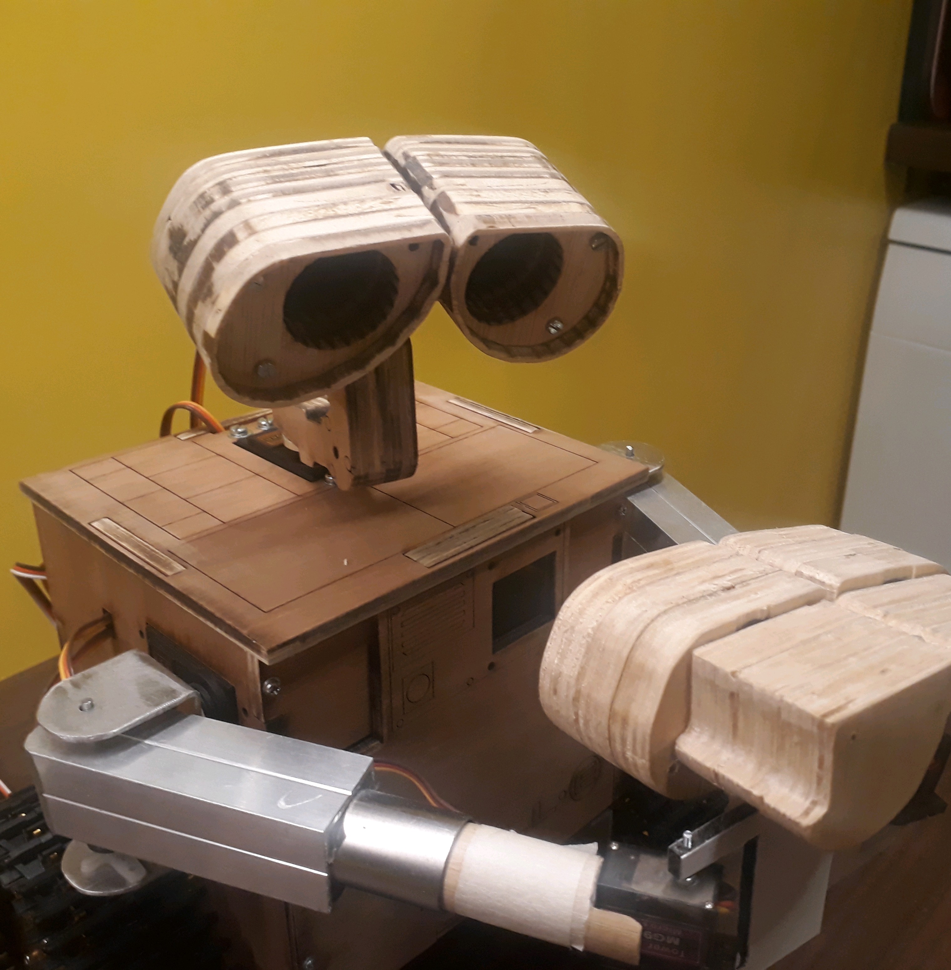
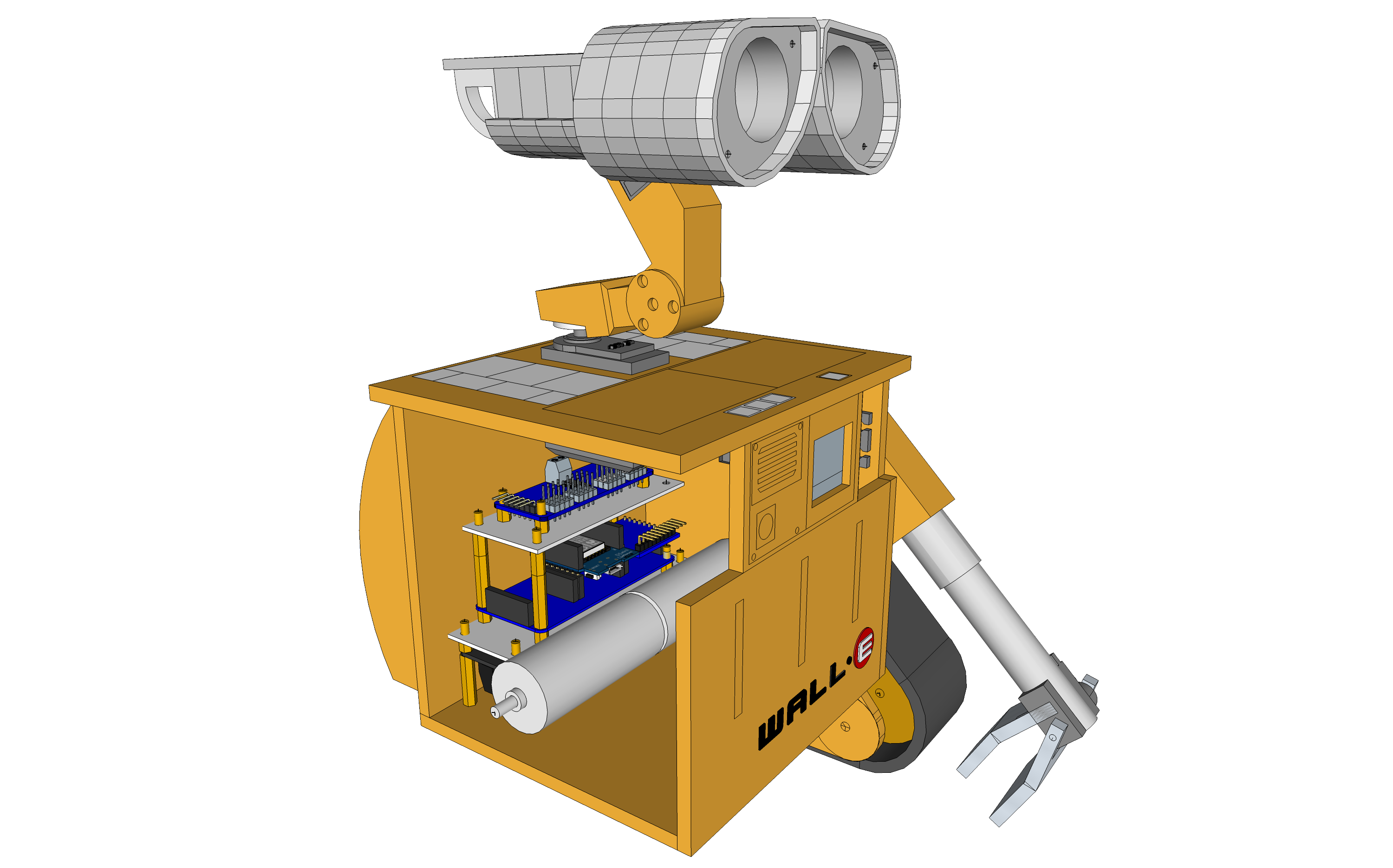
Wall-E
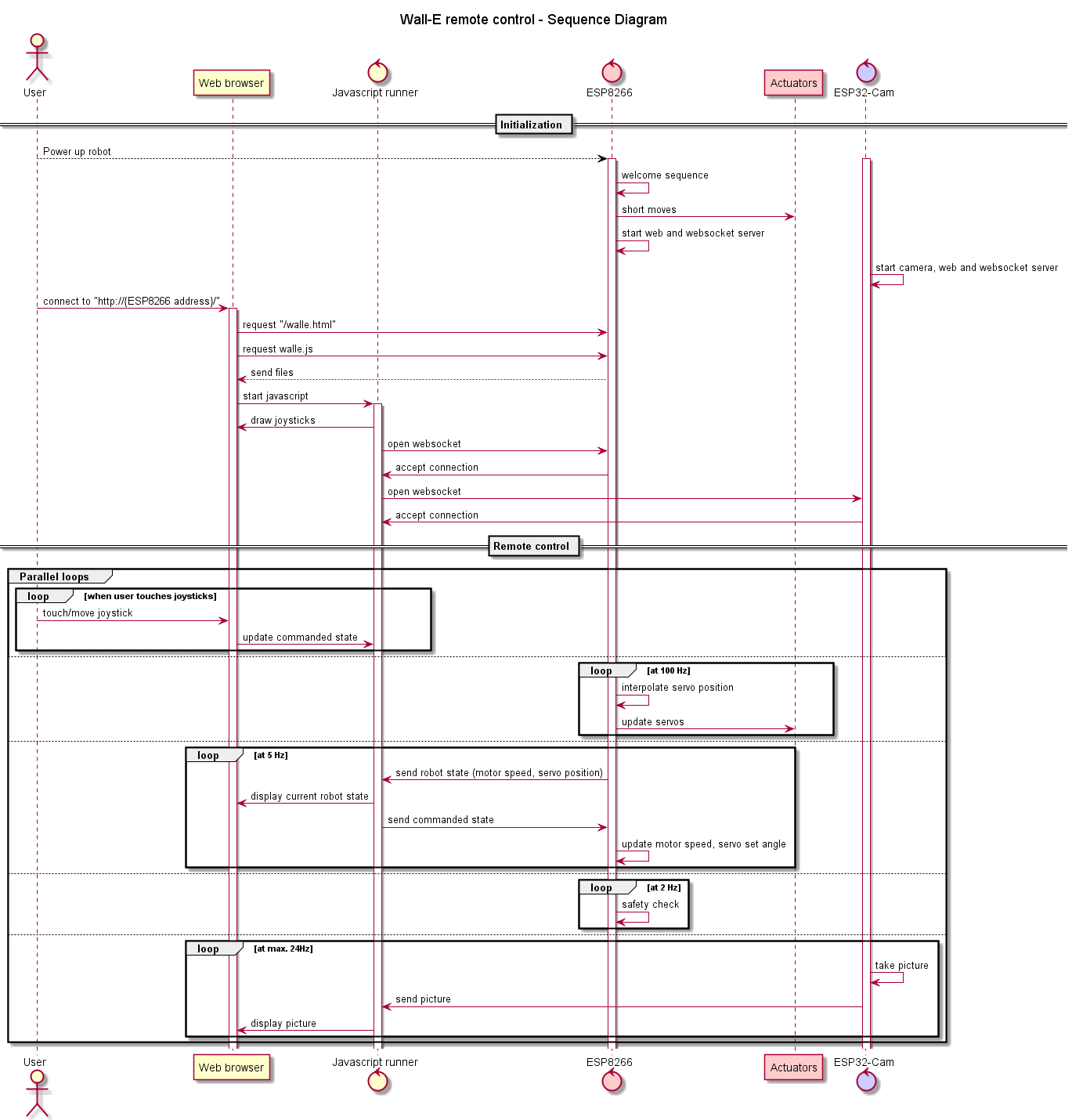
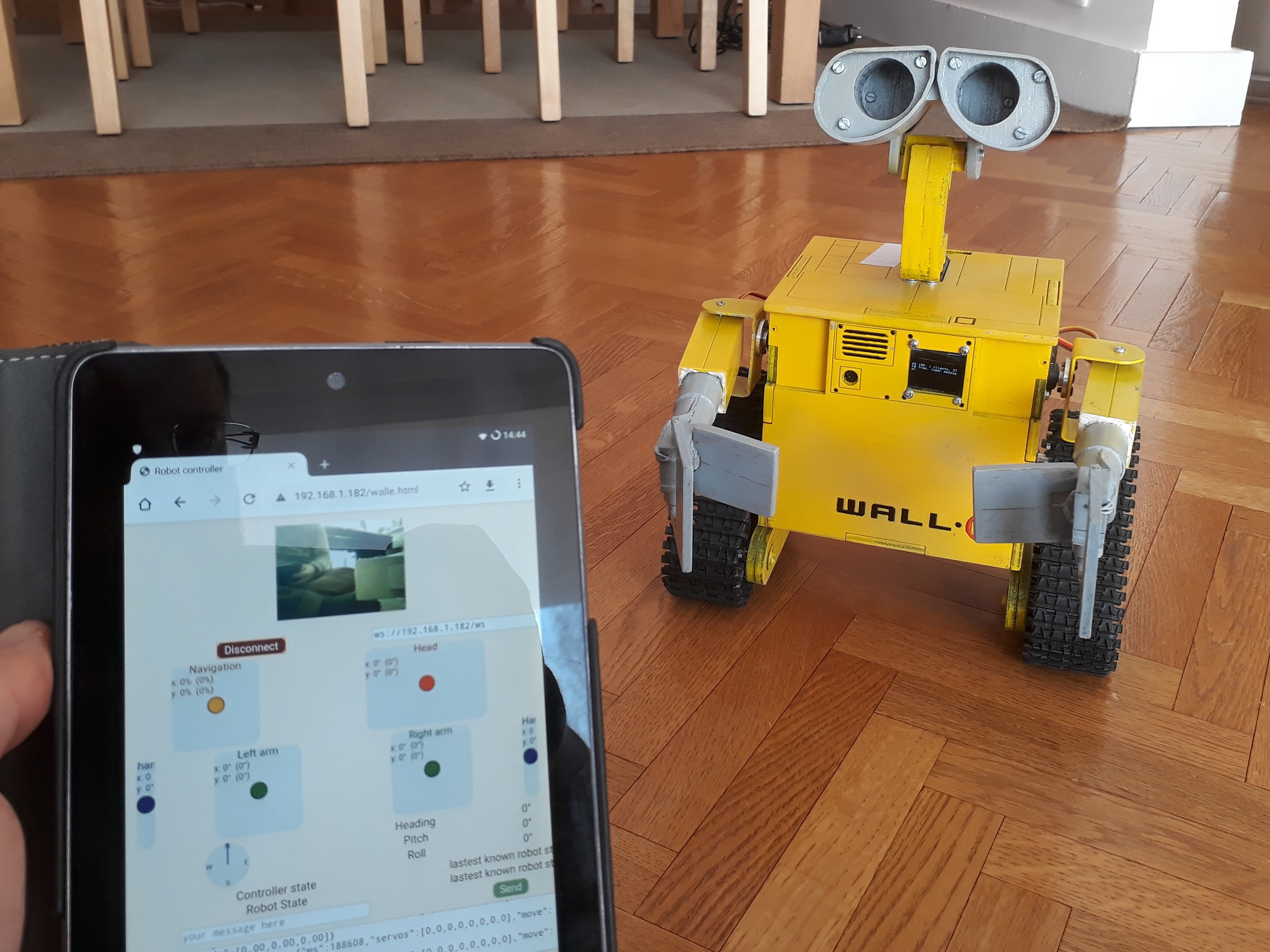
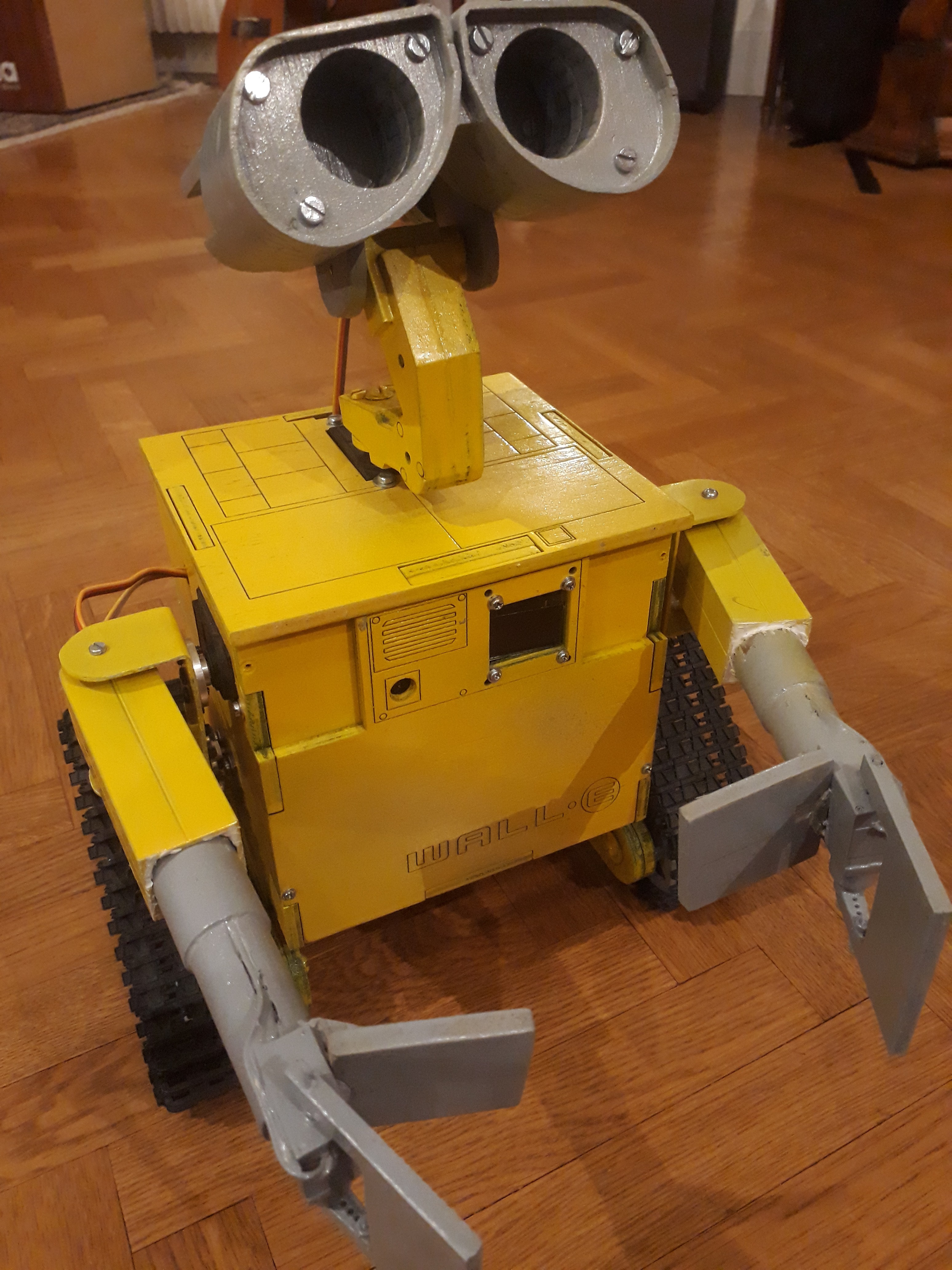
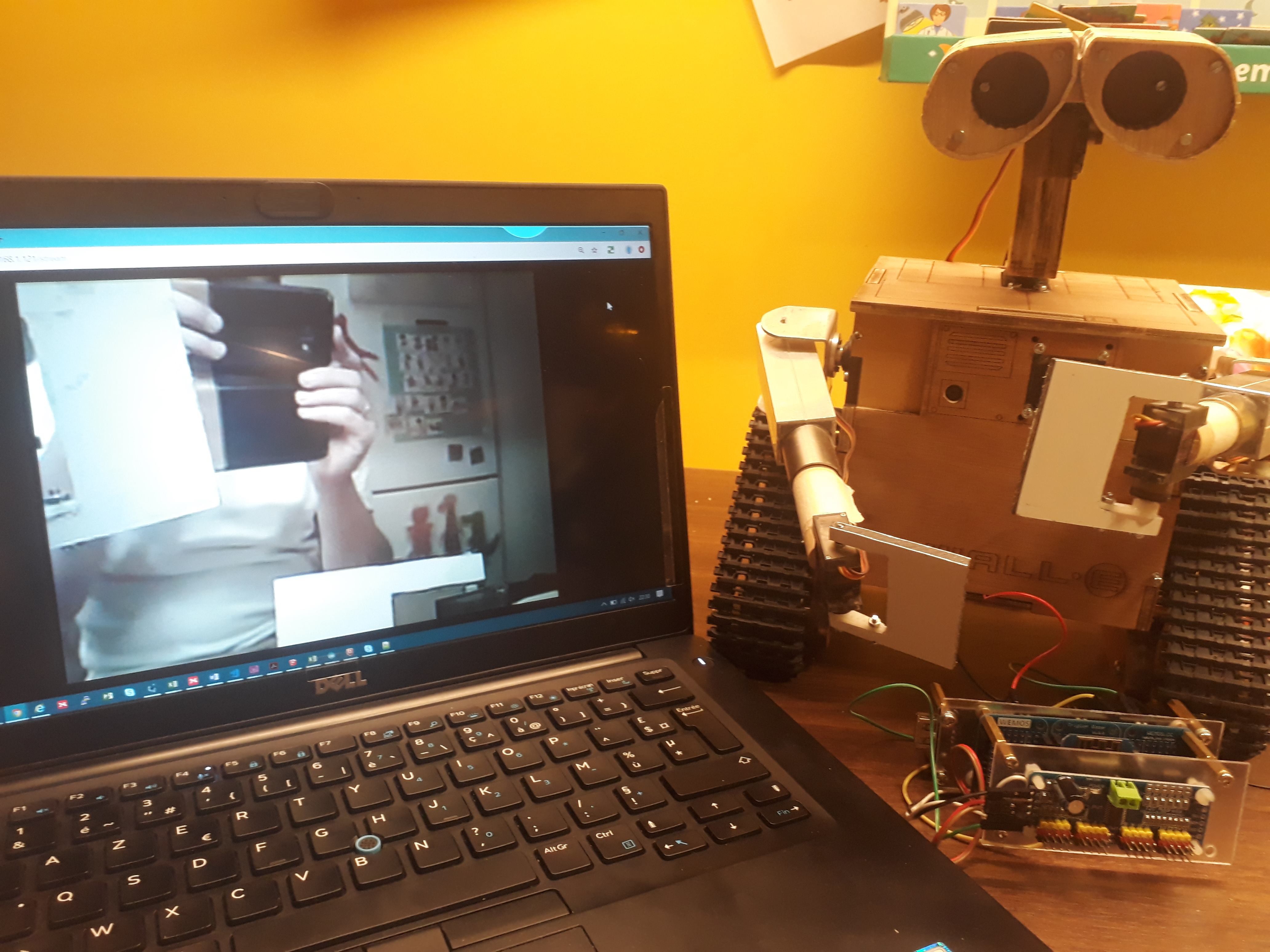
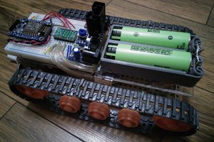
A small-size, low-cost, Wall-E robot. Remote controlled from a HTML5 interface, through WiFi websockets.
 Etienne
Become a Hackaday.io member
Already have an account? Log in.
Just one more thing
To make the experience fit your profile, pick a username and tell us what interests you.
Pick an awesome username
hackaday.io/
Your profile's URL: hackaday.io/username. Max 25 alphanumeric characters.
Pick a few interests
Projects that share your interests
People that share your interests


 Benjamin Broce
 ArsenioDev
 Tim Wilkinson
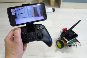
 hypnotriod
200ms latency on a local lan/wifi is *very* tame for websockets. For HTTP based control, you definitely picked the right framework. You could easily get a round trip time of < 10ms with this protocol alone. I'm sure your front end is adding to that, but it is a good place to start.