 danjovic
Circuit Descritption
The circuit consists of a couple of I2C EEPROMs that are connected to ATARI controller port.
The pins are pulled up through 10K resistors and the circuit provides one decoupling capacitor and one LED (with limiting resistor) for indicating power status.
The EEPROM has three lines to allow multiple devices on the same bus, bus according to the datasheet the TSSOP package for 24LC256 provides only line A2 for address select, being lines A0 and A1 disconnected.
Hence one of the EEPROMs is available at I2C address 0x50 (write at 0xA0, read at 0xA1), just like the original project, while the second EEPROM is available 0x54 (write at 0xA8, read at 0xA9).
How to Program
The post below has information on how to use SaveKey in your homebrews
http://atariage.com/forums/topic/249966-savekey-for-dummies/
To use the second eeprom change the base address in the macros provided
ORIGINAL ...
...
i2c_startread
; use V to flag if previous byte needs ACK
    ldy     #%10100001     ; 2 eeprom read command 0XA1
    .byte   $2c            ; 2
i2c_startwrite
    ldy     #%10100000     ; 2 eeprom write command 0xA0
    I2C_START              ;12 start signal ...
...
SECOND EEPROM
...
...
i2c_startread
; use V to flag if previous byte needs ACK
    ldy     #%10101001     ; 2 eeprom read command 0xA9
    .byte   $2c            ; 2
i2c_startwrite
    ldy     #%10101000     ; 2 eeprom write command 0xA8
    I2C_START              ;12 start signal ...
...
Just remember to contact the authors and reserve space for your game

 Timo Birnschein
 Kaili Hill
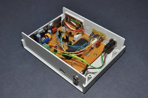
 Dilshan Jayakody
 Jeremy g.