 Yann Guidon / YGDES
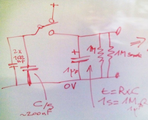
Last time (20161023) the kids wanted to build their own circuit. Well, fair enough : why did I even think I should limit the number of circuits anyway ? I'm only limited by the number of push buttons after all. So we built the following circuit:
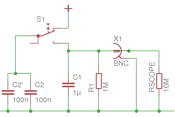
The 200nF charge pump lets the trace go higher faster but reduces the accuracy of the trajectory. It's always a matter of compromises...
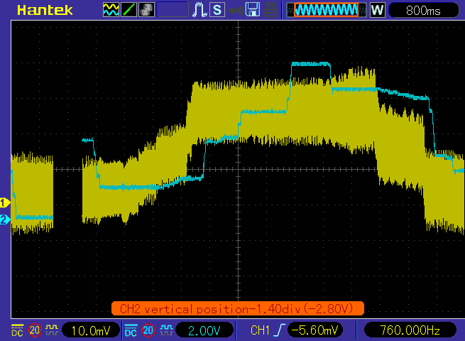
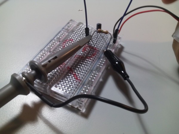
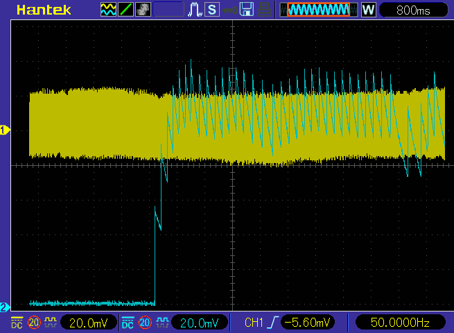
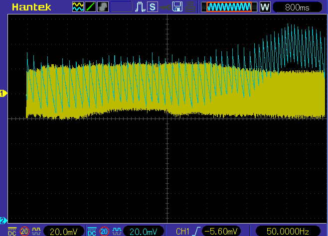
This time, we don't use a potentiometer to simulate the "walls". An external circuit is here to help us create a thick trace: a cold-cathode desk lamp provides a strong oscillation that we can adjust, in thickness and position, with the scope's knobs.
I had left the probes unconnected near the lamp's mains wire and when I pressed "autoset", the scope picked the high frequency induced signal. That's one way to show the direct effects of interference and EMI measures.
Now, this parasite could be harnessed, by placing the probe carefully, and the vertical deviation knob moves the "track" up and down.
If you don't have a CCFL, you can still create a high frequency source with discrete oscillators (for example with a 74HC04) but beware of the nasty habits of DSO, aliasing can make crazy shapes...
Another drawback of this kind of scope is the response time and granularity of the adjustments, which are not as good as analog where the reaction is immediate and more fun to use for such a game.
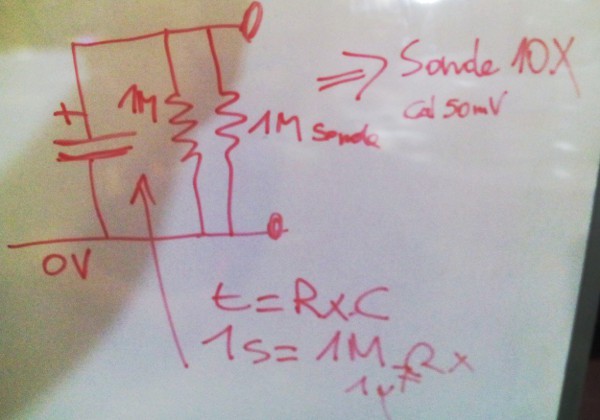
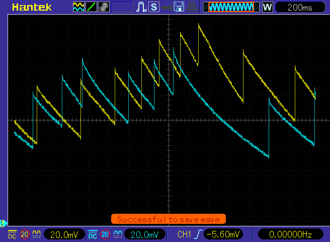
Let's now simulate the gravity : the altitude capacitor and the gravity resistor are wired in parallel then the typical RC (dis)charge curve is displayed on the 'scope (using the button as a push-button to recharge C1).
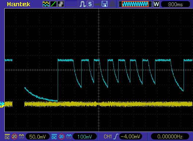
With two circuits, it's a bit more fun:
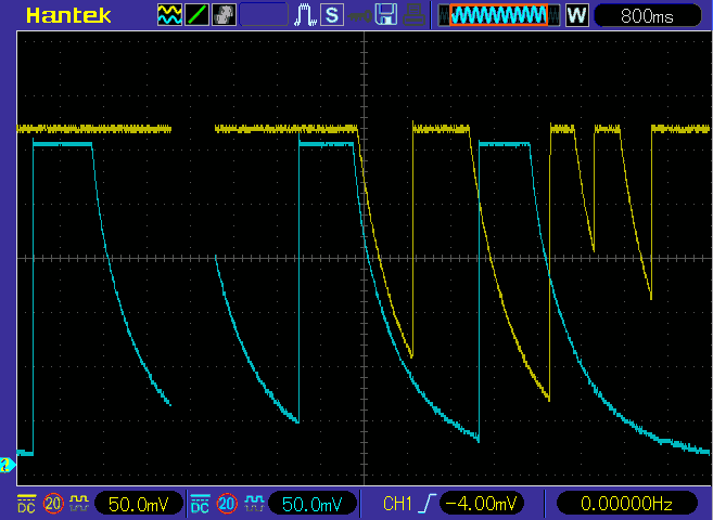
Now we have to add the "flap": a pulse "upwards", charging the capacitor, but with a limited amount. There must not be a direct connection between the altitude capacitor and the power supply, so the intermediary "flap" capacitor is charged instead, and discharged in the other.
The thought process is quite interesting, and tells a lot about electricity : it's made charges. Capacitors can hold those charges, which can be translated into current and voltage when they move or stay. We can control the flow and voltages through the values of the capacitors...
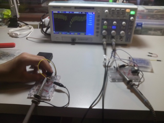
When channel 2 is left dangling, it picks up the CCFL's EMI and we can "play" with the traces again:
Discussions
Become a Hackaday.io Member
Create an account to leave a comment. Already have an account? Log In.
perty-slick with that "course"
Are you sure? yes | no