The filtration pump of a swimming pool does not support running on empty (that is to say without water). It's the same for a water pump. To solve this problem several solutions exist:
• An automatic water level device of the pool is responsible for ensuring that the level of water in the pool is always sufficient.
• A device monitors the level of water in the pool and prohibits the use of the pump when this level is insufficient and the pump may run empty
• A device monitors the phase shift (see fig 1,2 & 3) between the current and the voltage supplying the pump. When this phase shift is too large, it means that the pump is running empty. It must then be powered off.
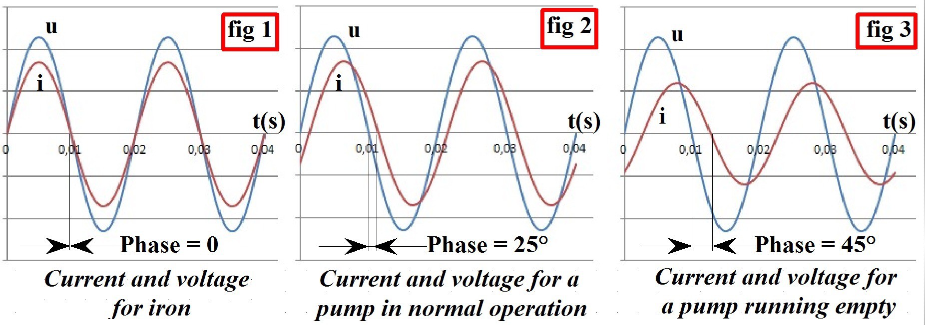
The third solution can only work with asynchronous motor pumps (most pool pumps and pumping) and it is this solution that I use in this project. It is more reliable to monitor the phase shift rather than the current value. This solution has the following advantages:
• No water level sensor
• The phase shift threshold corresponding to a no-load operation is relatively independent of the pump used. This is not the case of the current.
• The pool is only filled when it is deemed useful. If thunderstorms are expected in the 24H it is often useless to waste water ...
• It is easy to associate a programmer with times and filtering periods since the device plans to use a relay to control the pump.
My project is therefore the following (fig 5 & 6) :
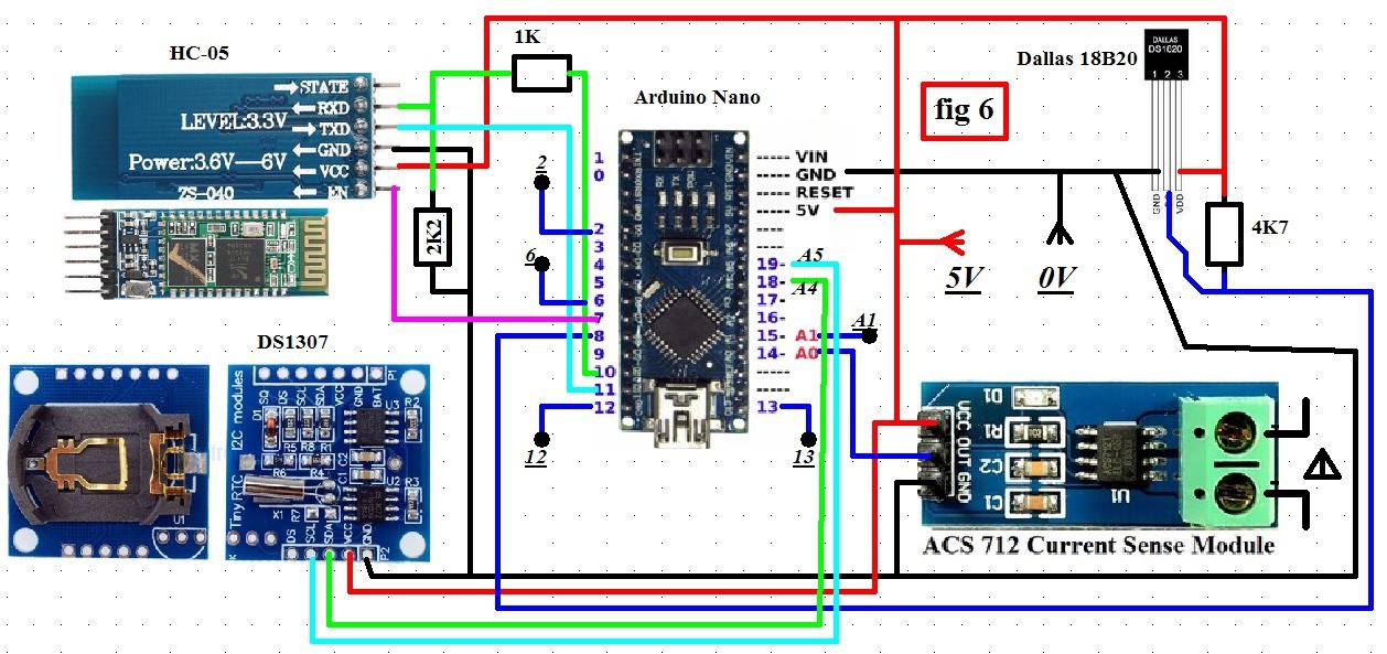
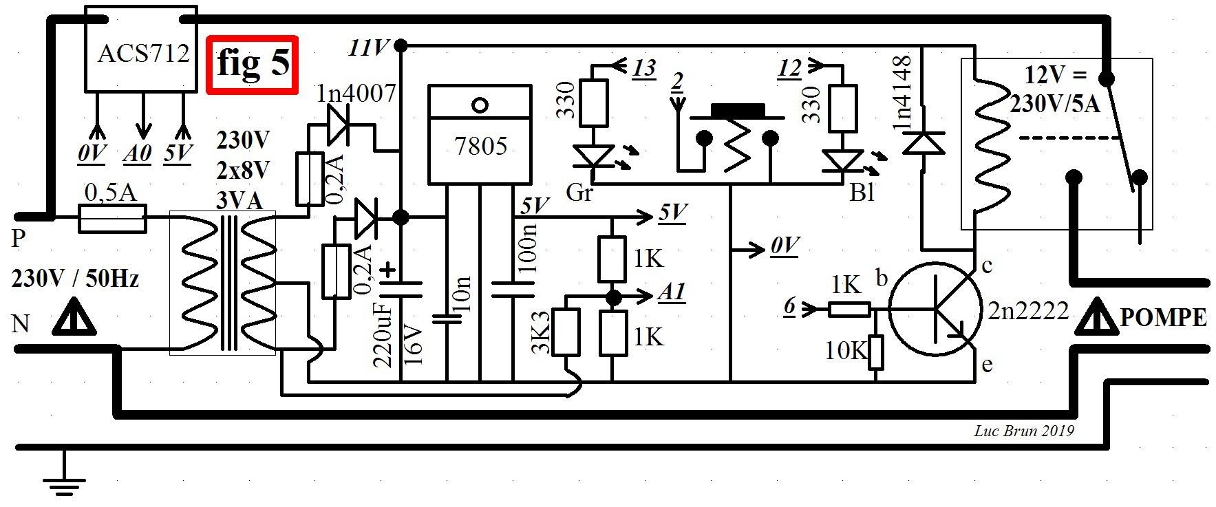
Pilot a relay to turn a pump on and off. Use an ACS712 current sensor to detect the current i over the duration of a network period (20ms in France since the network at 50Hz). The sampling frequency of an Arduino Nano (5V 16Mhz) is perfectly suited to this project. So to raise the network voltage u it seemed logical to use the secondary of a transformer that will take care of the power of the Arduino. I use a recovery transformer with output at mid point: 230V / 50Hz 2x8V 3VA.
In order to manage the useful periods of filtering it seemed useful to me to associate with the Arduino a RTC DS1307 and a temperature sensor DS18B20. Indeed, the daily filtering periods required depend closely on the water temperature.
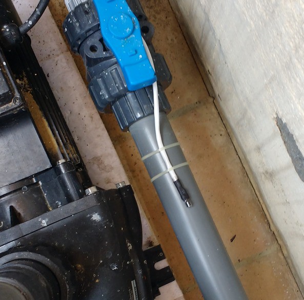
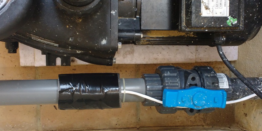
Simply put, the temperature sensor will be mounted with conductive thermal paste on the outside of a pipe, making sure to thermally insulate everything from the ambient air.
To visualize the information raised by the Arduino, I could use a small graphic display type OLED I2C SSD1306. I validated the project with a display of this type. But it seemed more judicious to use a Bluetooth module HC-05 thereafter. So I developed an Android application (with App Inventor) that allows me via the HC-05 module connected to the Arduino to drive my pump and receive the information that interests me such as the water temperature, the current in the pump and of course the phase shift. The use of the Android application is optional. See figs 7 to 11.
Finally, a simple push button and two LEDs on the case of the device allow me to turn on and off the Bluetooth module and control the pump in manual mode. After 10 minutes of inactivity the Arduino turns off the Bluetooth module. After one hour in manual operation, the Arduino returns to automatic mode.
To measure the phase shift, I proceed as follows: from 128 acquisitions of u and i (via A1 and A0) (in synchronism) over 40ms (2 network periods). Then I look in the series of u for the moment when u goes from a negative value to a positive value. From this moment I look for the first passage of i from a negative value to a positive value. The two moments I just described are separated from X acquisitions. As two successive acquisitions are separated by 20/64 = 0.322ms, the phase shift will be F = X * 0.322 * 360 / 20. Let F = 5.63 * X
Each series of acquisitions begins when u goes from a negative value to a positive value.
In the past, I had some problems with relays that were aging badly. Indeed, a relay that closes when the network voltage is large usually causes a current peak harmful to the contacts of the relay. In addition, a large current relay opening generates an electric arc that is also harmful for the relay contacts. Since I had already included a current sensor and a voltage sensor in the project, it was easy for me to implement the following functions:
• The relay must close only when the voltage is zero. • The relay must only open when the current is zero.
Of course, this is possible here because the pilot relay of the alternating current. It does not work in direct current. This relay is driven by the Arduino through a simple transistor mount (2n2222). In order for the above functions to be correctly carried out, I had to take into account the lapses of time necessary for opening and closing the relay. These timers were quite easy to adjust since on the Android application I visualize current and voltage, opening and closing the relay.
I also implemented some safety functions in the event of too much current (overload of the pump), error on the temperature sensor, temperature too low in winter ...
If there is a large phase difference between the current and the voltage, or excessive current, the pump stops. The next day, the Arduino starts the pump again, but if an error persists, it stops the pump again the next day and so on. The two leds of the box then flash in opposition.
The water temperature is measured only when the pump has been running for at least 5 minutes. This is to allow the piping on which the sensor is mounted to reach a temperature close to that of water. The temperature displayed in the Android app is the last measured when the pump was running.
In manual mode, the Arduino does not deal with errors. This allows for example to prime the pump or to connect a pool cleaner to the pump inlet.
During the first ten seconds of starting the pump, the Arduino does not take into account possible errors. This duration, which may have diminished in the program, seemed to me not to compromise the good health of the pump in case of idle operation.
Usage:
A brief press on the push button of the box turns on or off the pump according to its initial state. A long press on the push button of the box turns on or off the Bluetooth module according to its initial state. When power is turned on, Bluetooth is turned on (then turns off 10 minutes later).
The Android application has two display modes: Simplified Display and Extended Display. See fig 7 to 11. In simplified mode you can turn the pump on or off (as if you pressed the button briefly) but you can also read the current value, phase shift, date and time of the RTC, the water temperature, the state of the pump (error or not), the operating mode (manual or automatic).
In extended mode, current and voltage can also be displayed during normal operation, but also during the closing and opening phases of the relay. During these transient phases, the current and the phase shift are not measured and retain their previous values. The date and time can be updated on the BTI. You can also enter 'codes' online to perform various debugging actions (see help on the application) ...
Warnings:
This device is connected to the 230V / 50Hz electrical network, its realization is not within the reach of everyone. The indispensable rules of security for goods and persons must be perfectly applied. I present here a prototype whose realization by others can not in any case engage my responsibility.
The diagrams: see fig 5 & fig 6
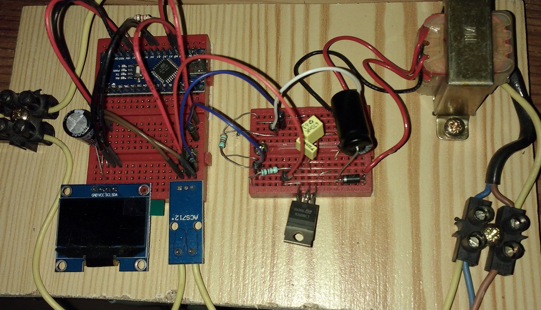
Photos: see end of document.
Possible errors:
If the current measurement wires are connected upside down on the ACS712 sensor, the phase difference between current and voltage will be close to 180 °. If you see this on the Android app, turn off the power, reverse both wires and everything will be back in order.
You have to choose a current sensor adapted to the pump you are using (5A for the one I used). It is also necessary to adjust in the Arduino program the parameters associated with the current measurement: maximum value, scale for Android display ...
I changed the default value of the speed of the serial link with the HC-05. By default it is 9600 Baud, I chose to set it to 38400 for this project.
Beware of the RX terminal of the HC-05 which should not receive 5V voltage. I used a divider bridge based on the two resistors 1K and 2K2.
The consumption of the system:
The voltage is supplied by the transformer, rectified, filtered, regulated by 5V. The consumed current by the controller is around 20mA when HC-05 is off and around 65mA when HC-05 is not paired. The relay takes its power directly at the output of the rectifier, a few milliamperes
The cost is around 30 € (see much cheaper if you want ...):
Clone Arduino Nano 5 €
HC-05 + ACS712 3 to 5 € + 3 €
DS18B20 + RTC DS1307 3 € + 2 €
Battery
LIR2032 for RTC 4 €
The case 5 €
1 push button & 2 leds (green and blue) recovery
Transformer 230 / 2x8V recovery
Regulator 7805 recovery
Capacitors, resistors and transistor recovery
Diodes, relays, fuses and fuse holders recovery
The settings :
The filtering strategy is to be refined in the program according to your use and the flow rate of the pump in relation to the volume of the pool.
I chose to run the pump for 10 minutes per half hour if the temperature is below 3 degrees Celsius. Above 3 ° C, the filtering times depend on the temperature of the water. This is to prevent the pipes from freezing in winters. The temperature rarely drops below -5 degrees Celsius in my region.
The maximum operating current and the maximum phase shift are also to be adjusted. Contrary to the maximum current the phase shift limit depends little on the pump and must be of the order of 30 to 45 degrees. The measurement error of the device on the phase shift is of the order of 12 degrees.
The current direction in the ACS712 sensor is important and is to be verified via the Android application.
The bridge consisting of three resistors 1K, 1K and 3K3 is intended to provide the Arduino (on A1) a voltage between 1 and 4V whose AC component is the image of the network voltage (fig 4). It is this voltage which will make it possible to measure the phase shift of i with respect to u.
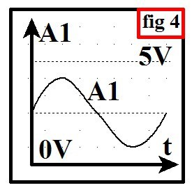
On A1 we have an image of u shifted positively. This is mandatory because the Arduino does not know the negative voltages. The passage of u from a negative value to a positive value is made by observing that A1 crosses the threshold of the offset of u (FIG. 4). If the three resistors above (1K, 1K and 3K3) had been well chosen, the threshold would have been the value 511. But in reality, this measured threshold is of the order of 425 because I did not seek to optimize my calculation of resistances. 425 is the value of the ZeroU constant of the Arduino program. This threshold is also the average value of the voltage measured on A1.
Possible (and unnecessary) simplifications:
After the debugging phase the Bluetooth module can be deleted. But we can not use the Android application anymore. The temperature sensor can be removed but this gain of 2 € is very harmful to the system. The RTC could be deleted but the Arduino program should be modified accordingly.
My mistakes :
The debug phase of the transfer of current and voltage curves from the Arduino to the Android application caused me some problems. In fact, it involves transferring 128 one-byte coded measurement points twice. As I chose to transfer each value in text mode, it is to transfer 2x128x3 = 768 bytes. The frame arrived wrong on the application. I first suspected the Bluetooth connection ... But I was wrong. The problem came from the variable 'String' called 'recep' which is used to send the data frame. It was too big and therefore difficult to manage by the Arduino. The solution was to cut the frame into subframes of reasonable size, with an '&' header and an end-of-frame character '@' and to use 'recep.reserve (112)' to set the receiver size.
My main mistake is to have chosen a box a little too small ... see photos.
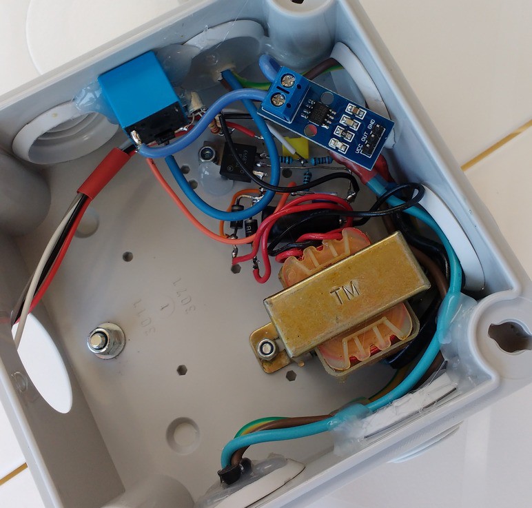
photo during progress
The improvements :
A WIFI module, type ESP8266, could be added to warn a person on his cell phone in case of error detected by the system.
The system has been working properly for several days. I tested the various features expected successfully. I made these documents because it seemed interesting to me to share the technologies that I implemented, especially the phase shift measurement and relay control.
I still have a lot to write, but it seems to me that I've said enough.
Luc Brun (Spring 2019)