Gertlex
Somehow, I was busier with life and work than I was during grad school, when I built my first two Mechs, so Numa 2 took me 3 years to finish. Major components of this work included:
- Converting the original Numa's C++ codebase into micropython (essentially python3.4)
- Customizing BB loader designs by others to achieve BB storage in the base, piped up to the turret
- This included using current based motor load detection, and LED + photoresistor detection of BB loading in order prevent the system from jamming itself
- Using Jupyter notebooks to evaluate the new (possibly better) leg designs, and validate walking gait code
As usual with mechs, during development, I tracked progress on this project over at the Trossen Robotics Forums.
Hardware
Numa 2 uses the following electrical hardware, most of which is off-the-shelf components:
- 14 Dynamixel AX-12a servos
- Pololu micro metal gearbox motor (not sure what gear ratio): used for BB loading
- 2 Pololu VNH5019 Motor Driver carrier boards: drives BB loader motor and airsoft gun motor
- 1800 mAh 3S LiPo battery
- 3V laser diode, driven by a simple NPN (?) transistor and a GPIO: used for aiming
- Amber LED + photoresistor, driven by a simple NPN (?) transistor and a GPIO: BB loader stops running if BBs are detected
- XBee Series 1 plus carrier board: wireless communication with Arbotix Commander
- Arbotix Commander: Arduino+XBee-based controller with buttons/joysticks for driving the robot. Sold by Trossen Robotics. Heavily modified, with a Wixel and OLED screen added.
- Analog camera + transmitter
The body of the robot is a combination of 1/32" carbon fiber plate, 3D printing, 1/32" polycarbonate, Dynamixel AX-12 brackets, and various fasteners, etc.
Switching to Micropython
Since I've started working on mechs, my real life work has moved me towards almost exclusively using Python. When I learned about Micropython, I wanted a project to use it on.
The first key step was to see if someone else had already gotten Dynamixel servos working with micropython. Luckily, the Hylands brothers saved me a lot of effort with their projects: Jon's uCee (github) and Dave's Bioloid library.
Then was the survey of what board to use. The biggest thing with mechs is that smaller boards are better. Initially I worked with the HydraBus board, but in 2017, I managed to fry the board, and couldn't get replacements at a reasonable price. At that point, I moved to the more conventional PyBoard - the reference board for using micropython.
Overall, micropython is great to work with. It aligns nicely with what I do at work, meaning that I have unit tests, mocks of hardware, plotting, and Jupyter notebooks. It has caused my C++ knowledge to get rusty, though.
Forced BB Loading
On my previous mechs, I handcrafted/tweaked a setup for feeding the airsoft gun(s) via gravity. This was mostly a passive approach, and depended on the jarring vibrations of the robot's walking to shake loose any jams in the BB supply.
For Numa 2, I wanted to try a forced BB loading setup, inspired by several robots built by R-Team members.
The majority of my loader is not visible on the assembled robot, as it is within the body of the robot. Here's some pictures showing its parts:
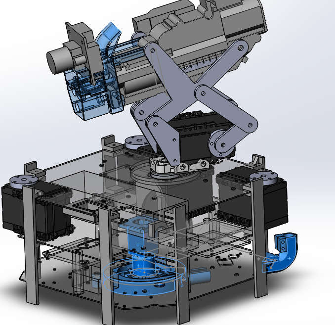
First, there's the 3D printed parts where BBs are fed into piping (not shown), as well as an elbow joint to convert to piping BBs vertically:
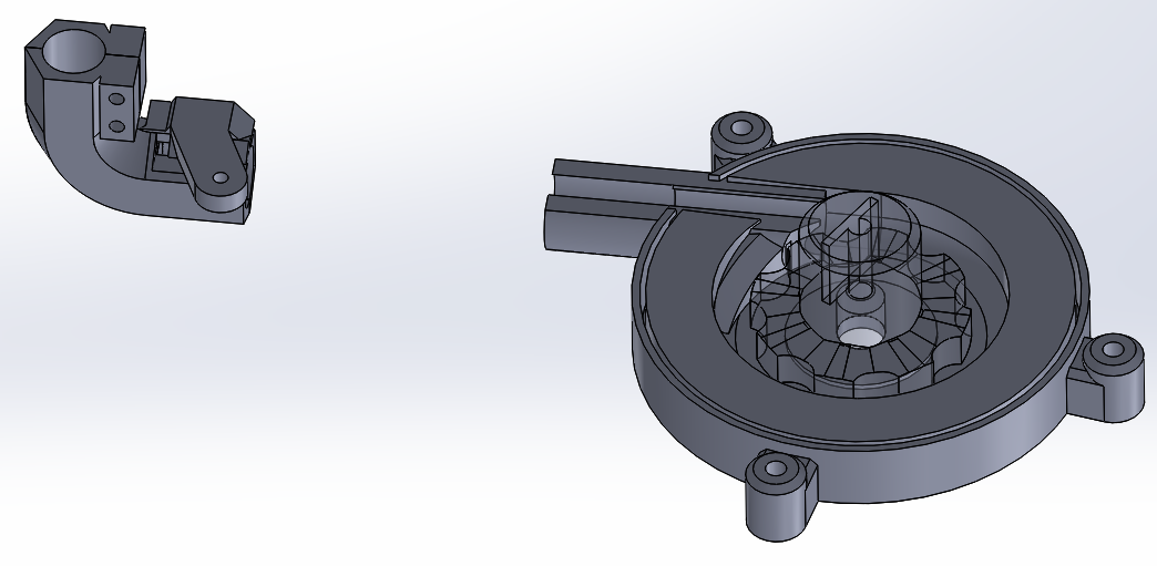 Some considerations in these parts:
 - Can drive the wheel reverse, to unjam (rarely happens)
- Smaller drive wheel gives slower load rate, but reduces the counteracting torque from the weight of BBs being pushed up to the turret.
- This is Rev 2 of the design; it accommodates for holes already created in the body for Rev1 which used a larger wheel. (what I'm saying is... the design looks funny)
- Using hard tubing, in this case 5/16" OD aluminum arrow shafts, minimizes the friction on the BBs being pushed through. This worked way better than using spiral wrap wire sheathing for the entire length.
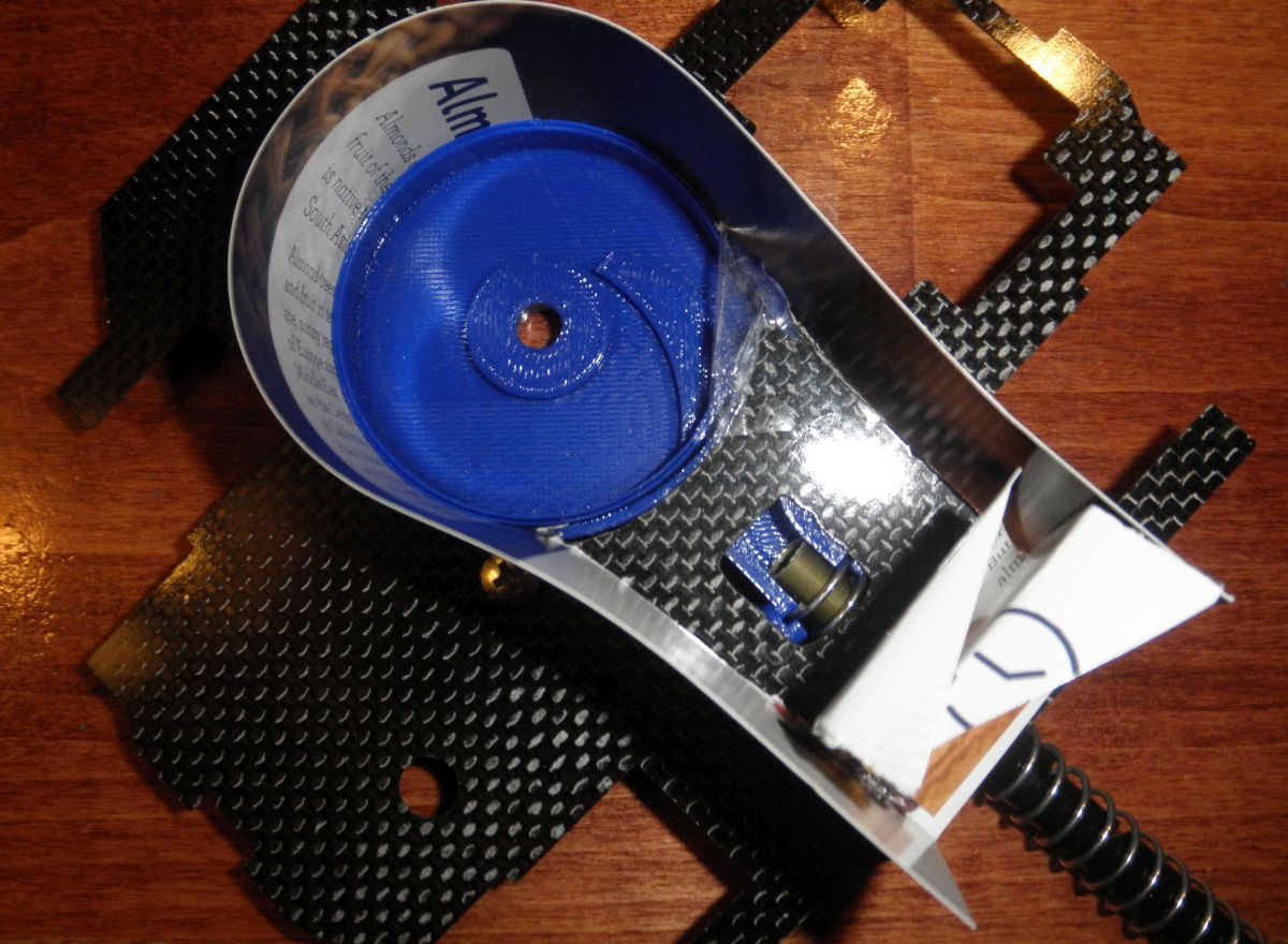
And the below is a picture of prototyping of Rev 1, minus the wheel, with the prototype BB holder made out of cardstock (a Blue Apron recipe sheet, it appears). Ultimately, I recreated the cardstock out of 1/32" thick polycarbonate, and changed the BB feeding angle to be about 30 degrees from straight back (so that the piping doesn't get in the way of the required score panels):
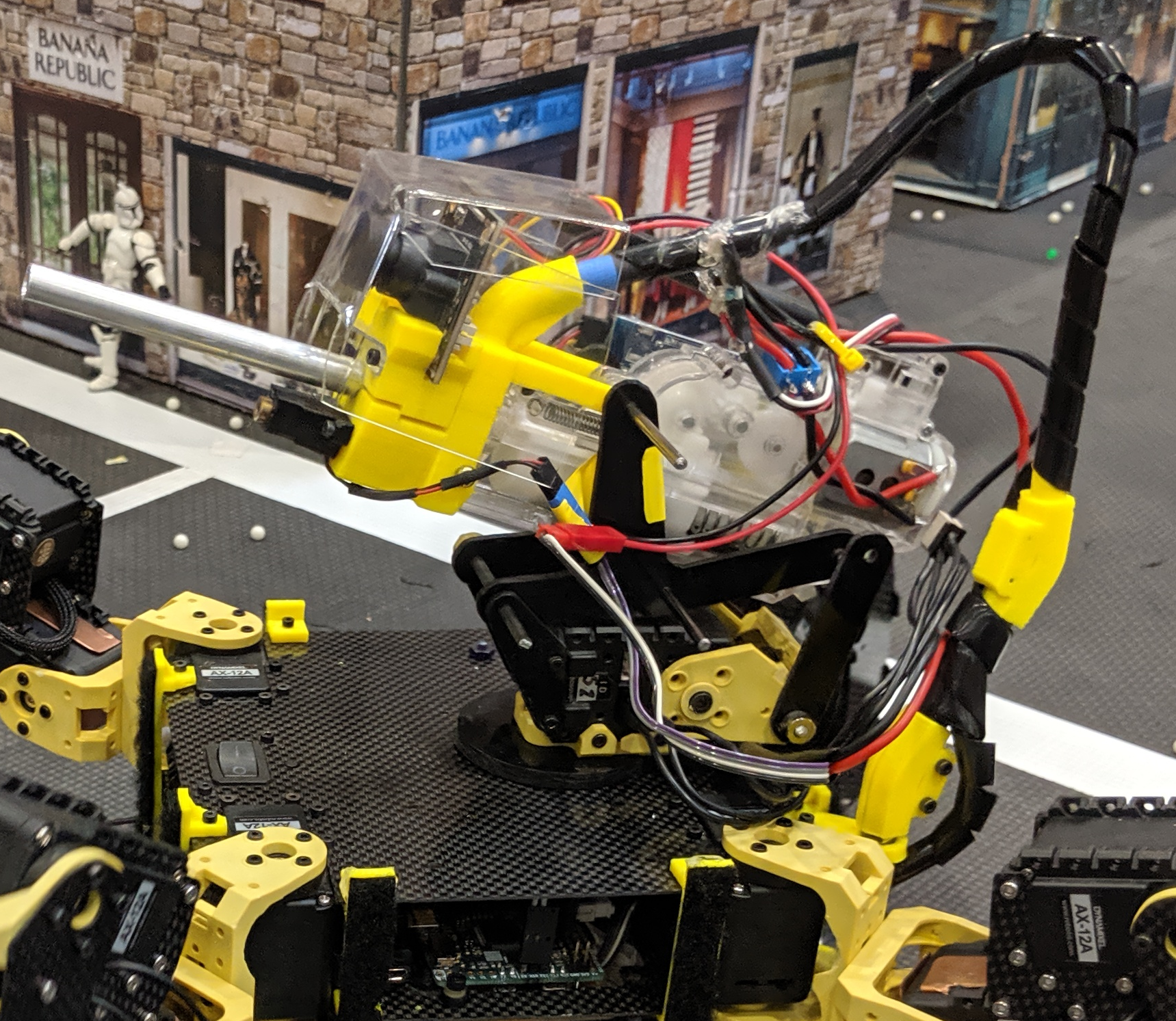
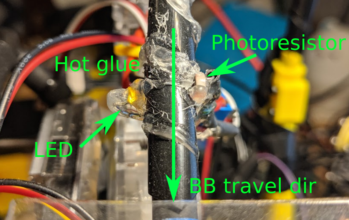
Where I most diverged from others' BB loader implementations, was in how I auto-fed the BBs. At the top, above the gun, I have an LED and a photoresistor, which detect if I have loaded BBs waiting to go into the gun (probably around 10 BBs). The loader will run until BBs are detected.
From conversation, it sounds like most other forced loaders are instead (1) timing their gun motor to do exactly one reciprocation of the mechanism and (2) running their loading motors for the precise amount of time to load one replacement BB at a time into the gun. My approach is quicker and dirtier; I just fire the gun for 100ms, which is one or two shots, and separately let the loader refill.
Fun fact... LED power math is hard (>_>), so first I had a resistor that made the LED too dim to get reliable readings... then I redid the wiring (and hot glue) with a different resistor. Works great now, except I'm dumping enough power in that the LED can melt the hot glue if left on too long!
Using jupyter notebooks for design
A direct follow-on to moving to Micropython is that Numa's code is 95% Python3, and thus I can interact with portions of the code via a Jupyter notebook (which, used to be called iPython notebooks, and are very similar in usage to Mathematica). With a bit of mocking of hardware interfaces, the robot code can be run in "simulation." Mostly, I used this to generate plots of the leg segments during the gait.
Here's the gait visualized as the leg segments move through one half cycle of the walking gait.
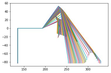
(note, this has some extraneous lines that would let me check for interference of leg segment edges, if I were drastically tweaking the design or gait)
And here's a plot of foot height and foot position (distance from the shoulder) for a half cycle of the walking gait.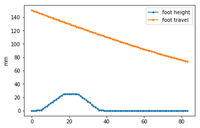
Less visually, the Jupyter notebooks was great when I needed to troubleshoot my gait without sending bad positions to the servos.
Final leg design (2019)
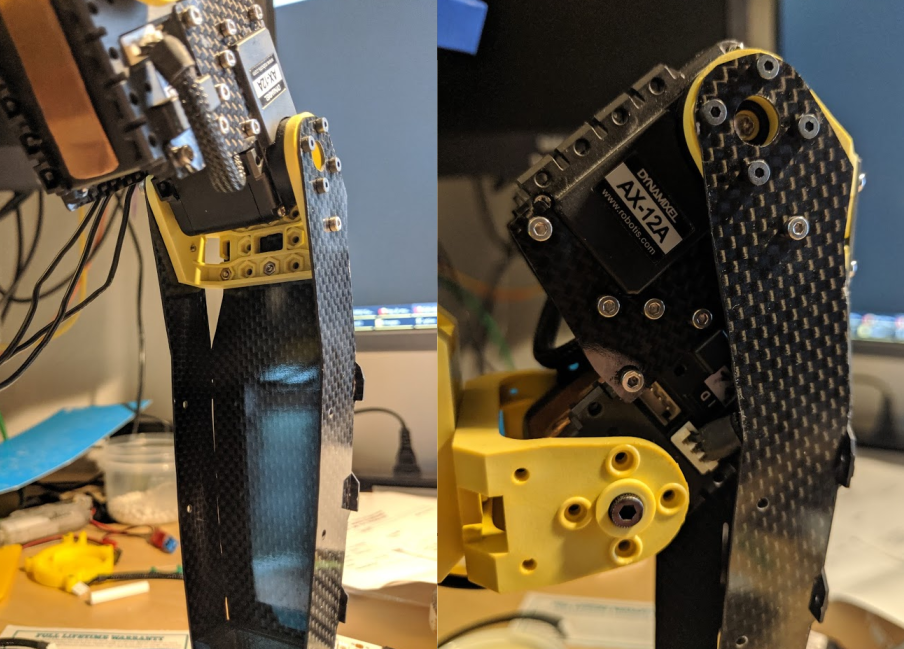
The final leg design isn't anything too novel, but there are a few things people have commented on or asked about. First, here's a side-vew of one of the legs:
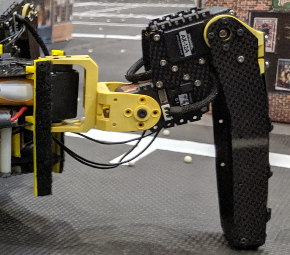
One question asked was why I designed the 2nd and 3rd servos in this "Z" configuration, instead of putting the 3rd servo in the last leg segment. My take is that the following factors are all slight positives for me:
- Keeps the weight of the 3rd servo ever so slightly closer to the axis of rotation of 2nd servo (which is the most stressed servo in each leg)
- Reduces the amount of wiring that is moving and twisting, so wire failure is less likely
- I didn't want to extend the leg any further from the body, and this design is very compact.
Then, as a bonus, once I started fleshing out the design, I realized that with a C channel style for the long part of the leg, it could fold on itself, giving a great range of motion: