Product Specifications
General
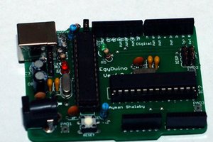
Type: Development Board
Architecture: For Arduino
Software: Arduino IDE
Flash Memory: 32KB
RAM: 2KB
EEPROM: 1KB
Clock Speed: 16MHz
Hardware Features
1. Fully compatible with Arduino sensors and modules.
2. Integrated with an ATmega328P microcontroller.
3. Features 14 Digital I/O Pins (6 PWM outputs).
4. Features 6 Analog Inputs.
5. Features an ISP Header.
6. Is Arduino Uno R3 Shield Compatible.
7. Uses a micro-USB programming input and power supply.
8. Has 3 On-board Grove connectors.
9. Features a 3.3v/5V system operation power switch.
10. Consists of additional pads aligned to 0.1” grid.
Power
DC Jack Input Voltage +7 -15 volts
Output Current (5v): 500mA max. (with micro-USB) & 2A max. (with DC Jack Power)
Output Current (3.3v): 500mA (from both sources)
DC Current per I/O pin: 40mA
Weight and Size Dimensions
Product Weight: 26g
Product Size (L x W x H): 68.6mm x 53.4mm x 11.6mm
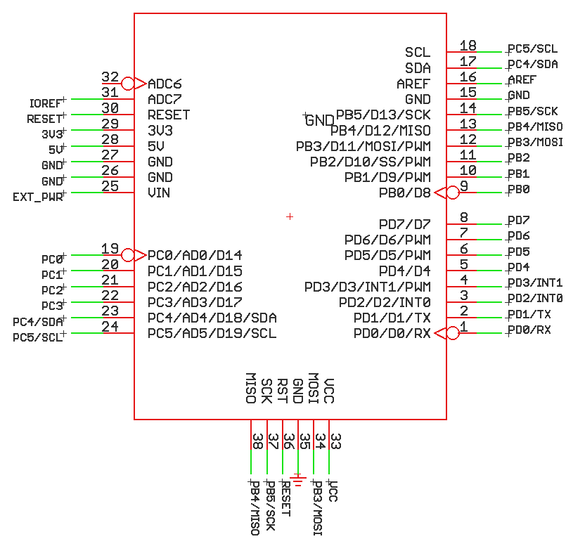
Pinout
Product Review
Throughout my test of this development board, I found out that there are some very unique touches to this module which is unlike to any other development board including:
1. A very uncomplicated and simple setup with an easy way to program.
2. There're straight-forward pinout markings and clearly marked labels.
3. There're empty pins on the PCB for female pin headers to be added as well, give capability to multiple types of jumper wires.
4. This board has 3 on-board Grove connectors, so it is compatible with all Grove inputs and outputs.
5. This board has pins for direct serial communication.
6. It is based on surface-mount components mostly.
7. There is a power operation switch, switching the board between +3.3 volts and +5 volts to cater for different sensors and modules.
8. It includes solder pads at the back of the PCB for additional, external connections.
9. There is not a need for any installation of drivers this microcontroller for programming on the Mac Operating Systems.
There are aspects that needs to be improved such as the roughness on the sides of the PCB, and, the DC input jack isn't properly aligned with the board.
Arduino Seeeduino v4.2 Sample Code
void setup() {
  pinMode(LED_BUILTIN, OUTPUT);
}
void loop() {
  digitalWrite(LED_BUILTIN, HIGH);
  delay(1000);
  digitalWrite(LED_BUILTIN, LOW);
  delay(1000);
}
Seeed Studio Product Page
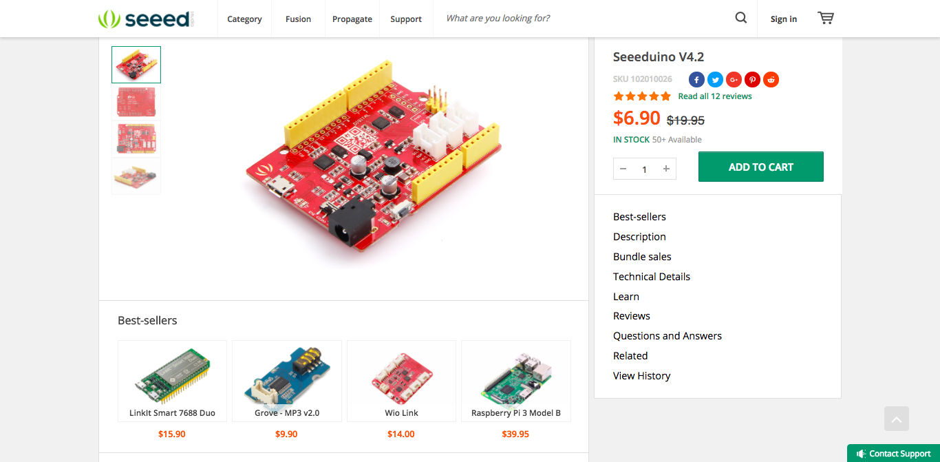 Check out the product here: https://www.seeedstudio.com/Seeeduino-V4.2-p-2517.html
Sponsor Link:
UTSource.net Reviews
It is a trustworthy website for ordering electronic components with cheap price and excellent quality.
Amazing opportunities
Also, be sure to check out PCBWay, a leading manufacturer and distributor in PCB design and manufacturing. They have amazing prices and excellent quality in their services, so don't miss out on them! Plus, PCBWay has an amazing website, online Gerber viewer function and a gift shop so make sure to check out their links below:
PCBWay Free Online Gerber Viewer Function: https://www.pcbway.com/project/OnlineGerberViewer.html
PCBWay Gift Shop: https://www.pcbway.com/projects/gifts.html
Be sure to check out the Seeeduino v4.2 setup by clicking here.
Enjoy! Contact us for any inquiries!
 Lithium ION
 Dr Ayman Shalaby
 OzQube