 Patrick
Background
This is my fourth or fifth iteration of this basic circuit.
When I started doing rPi bare metal program I used FTL232 serial-to-usb modules to connect the rPi serial port to the PC in order to download programs, monitor serial output, and do some basic input to my programs.
In time I decided to use a Teensy 3.2 instead of the less expensive FTL232 board, especially since with the Chinese clone FTL232 boards I have, and in conjunction with the stupid behavior of Microsoft Windows with regards to polling and resetting comm ports, I eventually decided to (a) use a Teensy, with it's multiplicity of hardware serial ports, to hook up to the Pi and (b) write my own terminal program / rPi programmer for uploading programs.
The circuit can be easily put on a small, separate, breadboard, you don't have to use the breakout setup I have here. But the other thing I got really, really, really sick and tired of, especially with additional hats on the Pi with cheap pins, are/were the dupont female connectors and always having to fuss with and sort out the rPi pins every time I wanted to simply change a hat. The connectors continually fail to make good contacts, and it's a pain to try to connect devices, and disconnect them, and then reconnect them, to the male pins of the rPi connector.
So, at this stage of the game I have created a board that stays hooked up to the rPi, provides me with some basic functionality, and allows me to change hats and/or play around with different circuits without worrying so much about bad connections, or the time it takes to rewire a circuit.
Connections
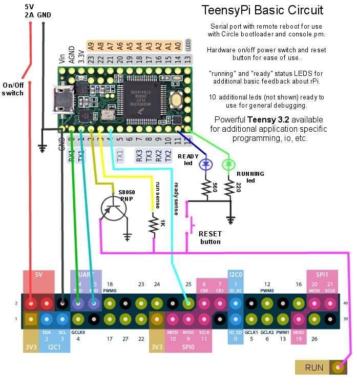
Teensy GPIO 0 and 1 (RX1 and TX1) are connected to the rPi UART pins 4 and 5 (TXD and RXD) respectively.
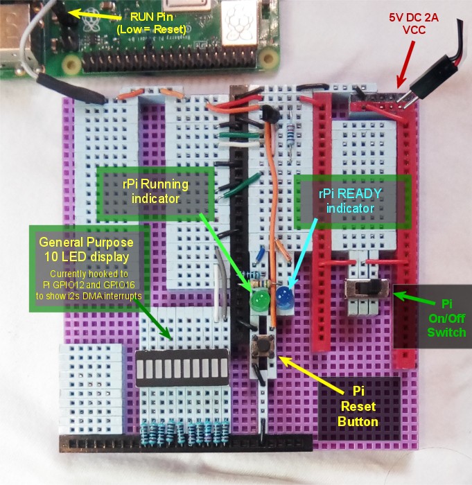
The Pi RUN pin is connected to a PNP transistor that is controlled by Teensy GPIO 2. When Teensy GPIO2 goes high, the Pi RUN pin is grounded, and the Pi is rebooted. There is also a reset button wired in parallel with the transistor so you can just press the button to reboot the rPi. The state of the rPi run pin is sensed by Teensy GPIO3, which is then reflected back out GPIO12 to a green LED.
I use the PI GPIO25 connected to TeensyGPIO4 to sense a "ready" state for the Pi. This is simjply a single line of code in my generic Circle kernel.cpp programs, in the Run() method usually, indicating that everything is setup and the program is running correctly. The state of the "ready sense" pin is reflected back out Teensy GPIO11 to the blue LED.
Besides that, there just an on off switch for the rPi power. Some of this is obviously to taste, or based on your circuits, but the micro usb connector on my Pi is wearing out and I also wanted a way to provide VCC without changing wires every time I change a hat, so that is integrated into the circuit as well.
Breakout Board
(note: the Hackaday editor is not working well for me, I cannot consistently format text and weird things happen if I try)
These are commonly available oh ebay etc, and often come with 50 pin cable connectors. I don't like the cable connectors, or that whole approach. Often the cable length is an issue, and the way they work is that the cable has to be connected to the top hat, so still every time you change a hat, you have to change the cable. The cables are also big and unwieldy and I have a very limited amount of room in which to work.
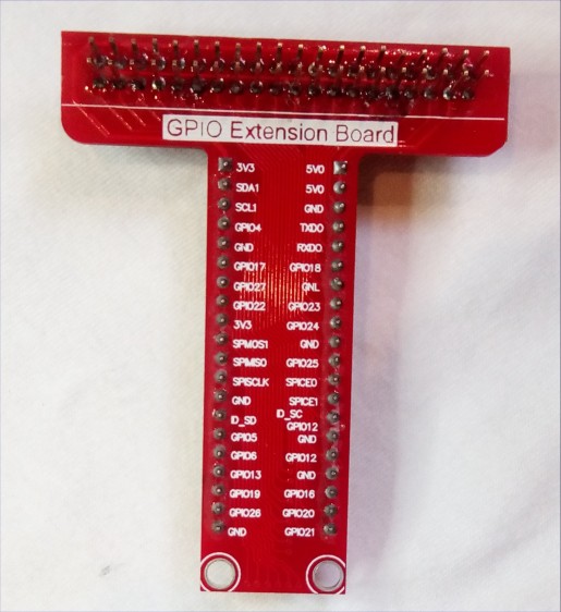
Unfortunately, mine came with the usual cable connector on the top and male pins on the bottom, so I had to remove them and put a new header on it. One nice thing I learned was a better way (for me) to remove the solder from the 40 holes. Works especially well with a hot-air soldering machine but probably good with a soldering iron too. I heat up the connections then stick the nozzle of my shop vac up there and lol. You...

 Bill Peterson
 RodolpheH
 Andrew Mitz
 Jeremy