 Kevin Kessler
Several 3D printed parts were installed into the mailbox. I haven't uploaded the STLs anywhere, since it is unlikely that anyone has the same Home Impressions mailbox that I do, but I will provide them if someone asks.
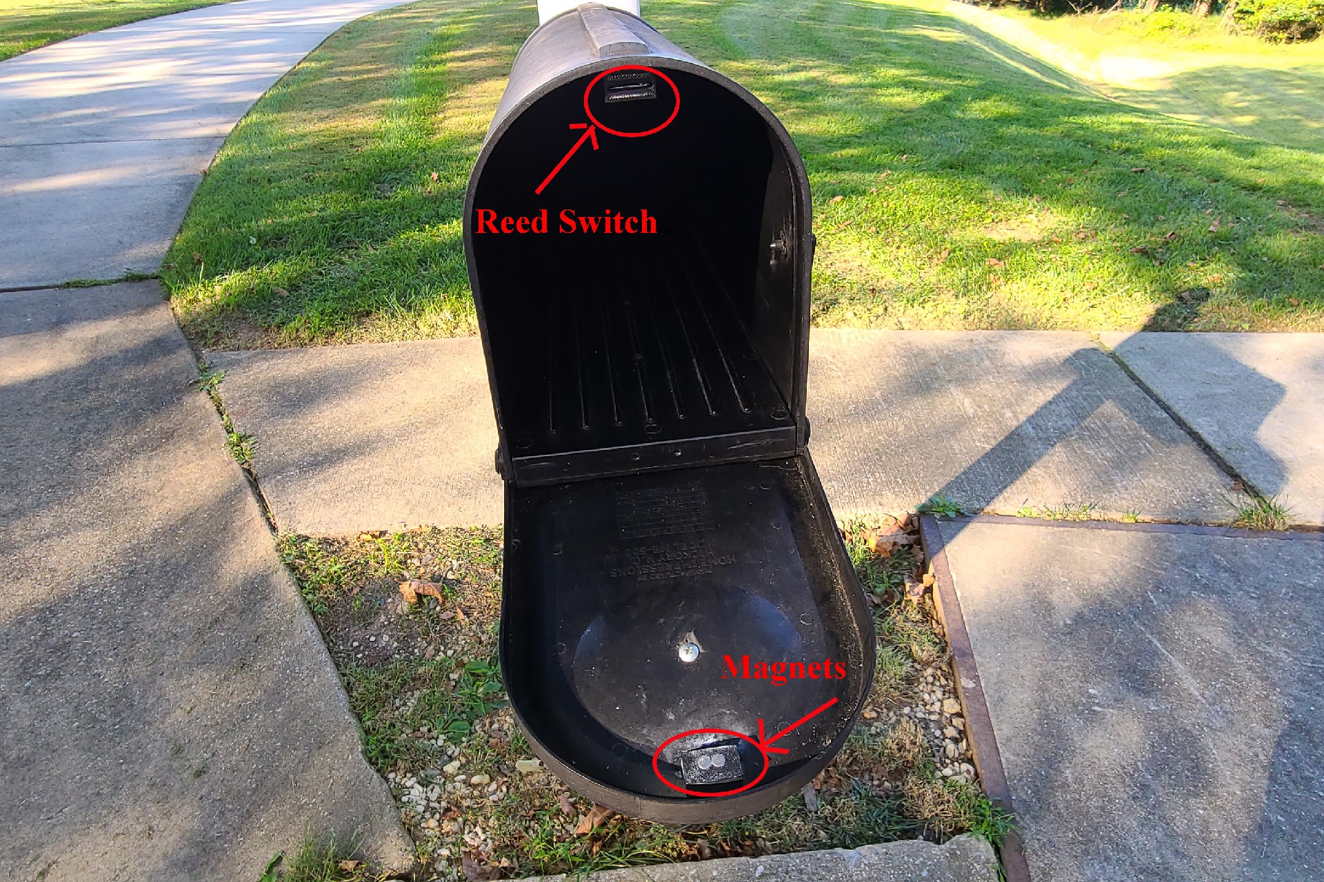
The reed switch is normally closed, so that, when the mailbox is closed, the magnets engage the reed switch and open it, letting no current flow. The 3D printed holders for the magnets and switch are just glued in place, along with a wire channel glued across the top of the mailbox to guide the reed switch wires to the back of the mailbox.
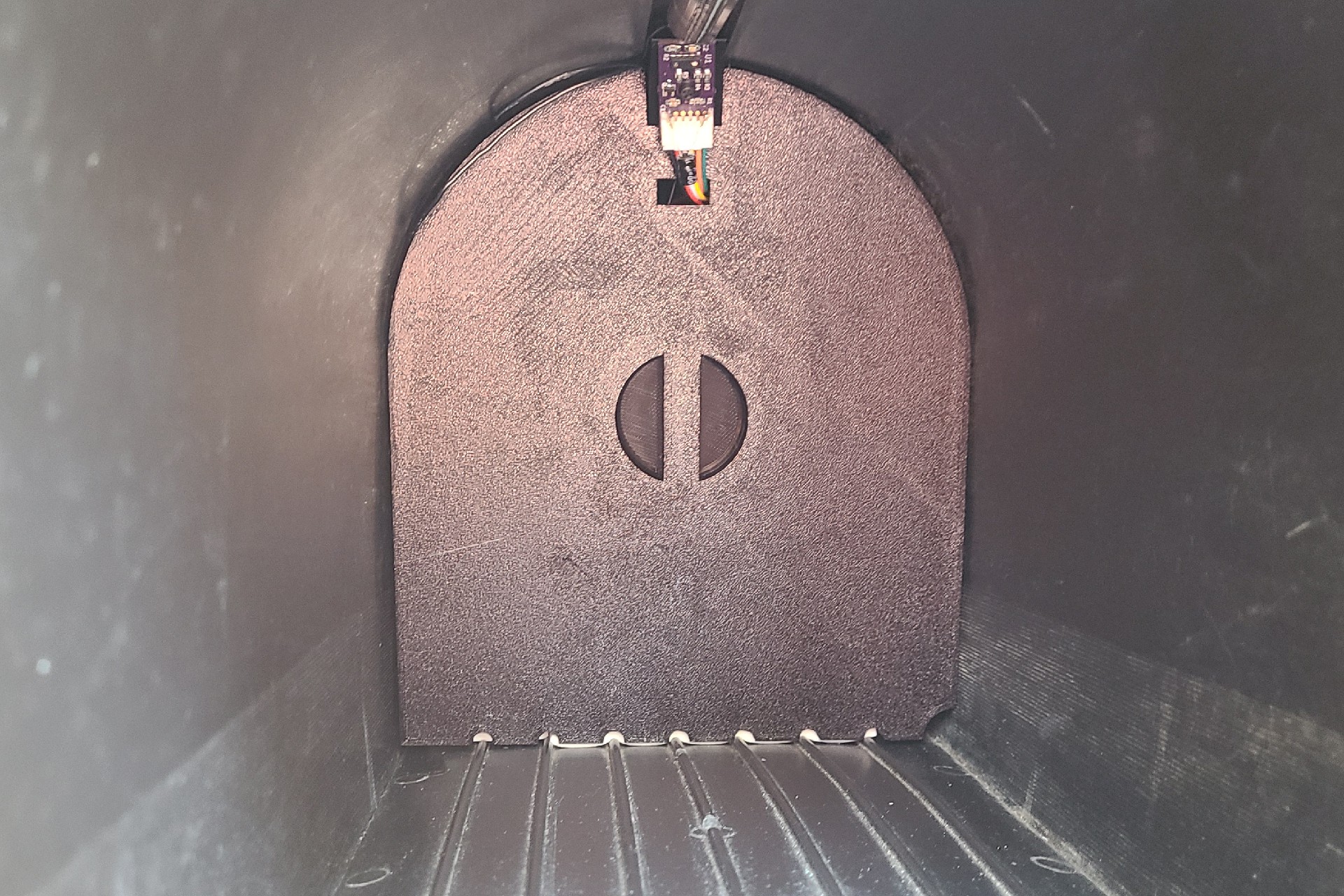
This is a picture of the false back in place in the mailbox.
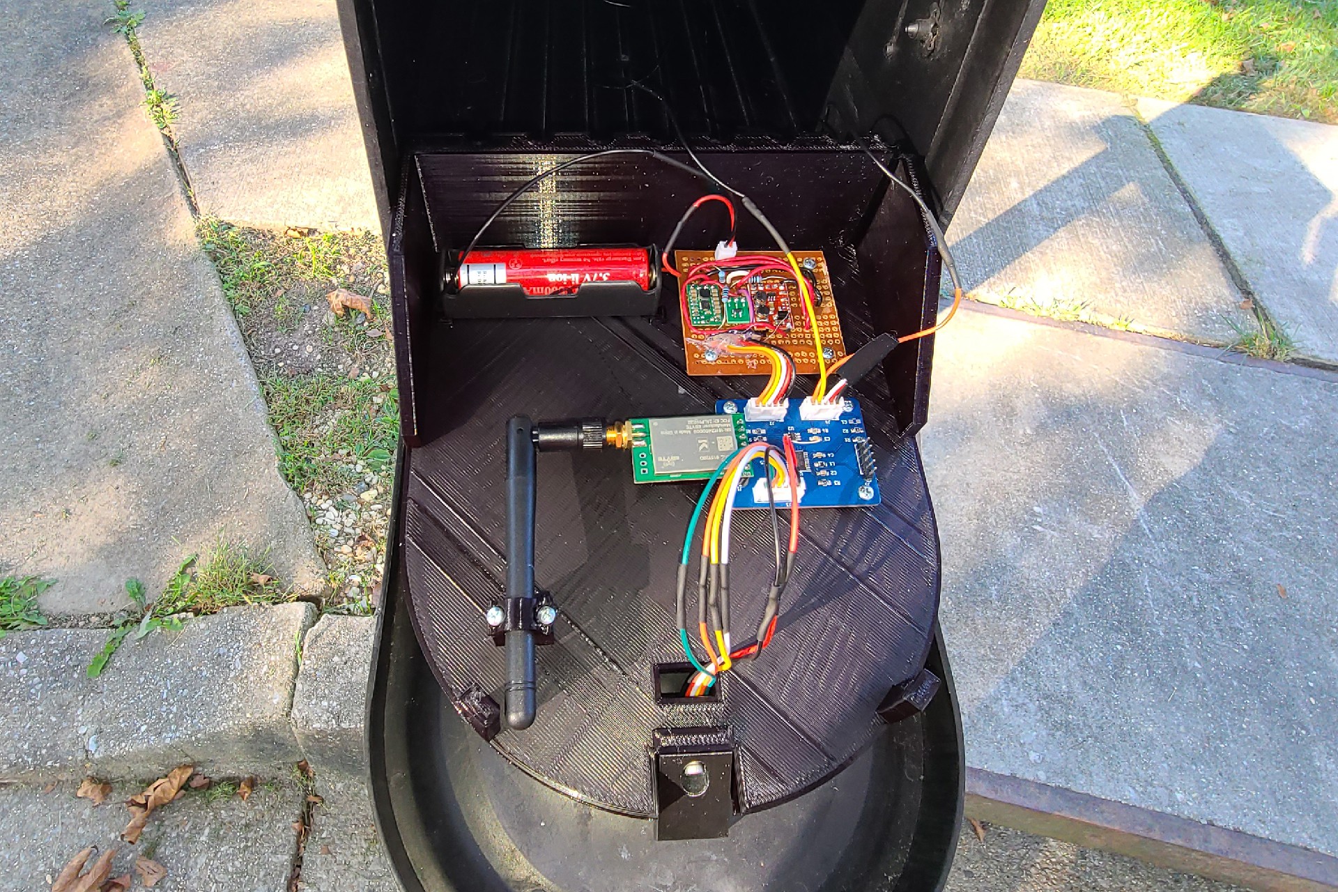
This is a picture of the electronics housed in the false back of the mailbox. The blue PCB is the processor board with the STM32L0 chip, and the perf board contains the 3.3v buck/boost converter and the 5V boost converter. The bundle of wires going through to the front connect the proximity sensor to the processor board.
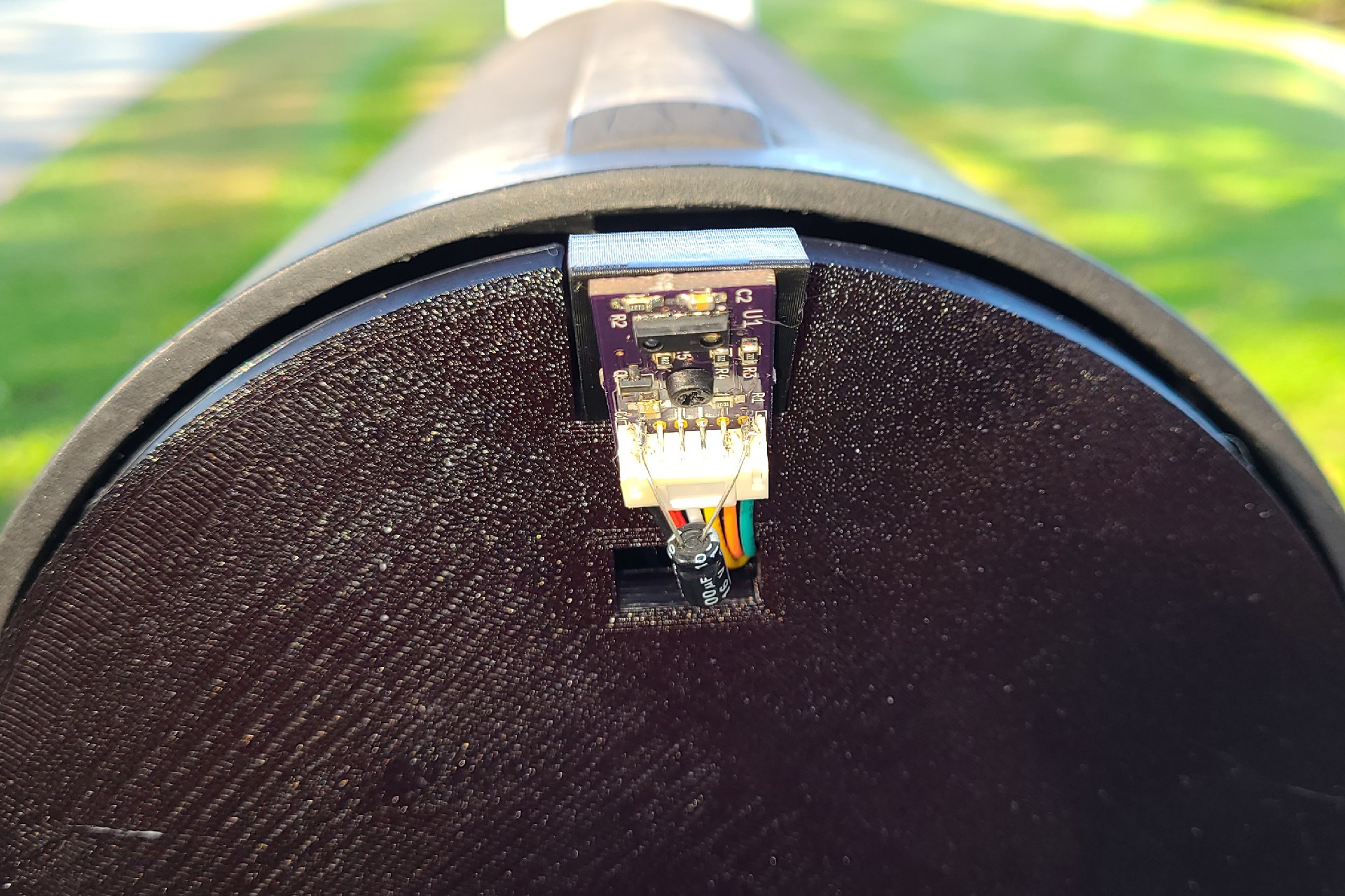
This is a close up of the proximity sensor on the front of the false back, which fits nicely into the groove on the top of the mailbox. The capacitor bodged onto the PCB is across the 5 V supply for the IR LED. This helps supply the high current pulses required by the IR LED.
Discussions
Become a Hackaday.io Member
Create an account to leave a comment. Already have an account? Log In.