 jed
jedProject Goals:
. Interesting for at least most of the grandchildren
. Quick enough to be completed during our summer week together
. Not too expensive, since 9 * (expensive) = prohibitive and I need one for myself, too
. Simultaneous control to allow racing - necessary to get the interest of some
Simply building a line-following robot would probably interest between three and five of the nine grandchildren. Adding the ability to control them with a phone or tablet and then to RACE them against each other will probably get the rest involved.
So, what sort of control from the tablets and phones? First I considered Bluetooth, but I fear that the multiple robots being controlled by multiple phones over Bluetooth would interfere with each other. Since simultaneous control is a MAJOR goal, that is OUT.
I settled on trying short UDP datagrams that set the state of the robot, with the processor on the robot taking it from there. Any WiFi network could support more robots than could fit into a room, so this seemed a good target.
Digression: UDP - User Datagram Protocol is the text message of the TCP/IP world. No "phone call" , no connection, just squirt out a limited size transport-layer datagram with no promise of delivery. The minimal requirements and overhead are just right for this application.
Next I needed to decide on the hardware to be carried on the robot. To me the choice was obvious - some version of the ESP8266. It has all the capability I need in an inexpensive package. I can't use the smallest versions but some ESP8266 Mini NodeMCU version has all the power plus easy implementation that I could ask. I found a three-pack at Amazon for $13 with amazing one day shipping and I found many on eBay for less with not so amazing one month shipping.
Link to single example on Amazon
I purchased samples and started developing.
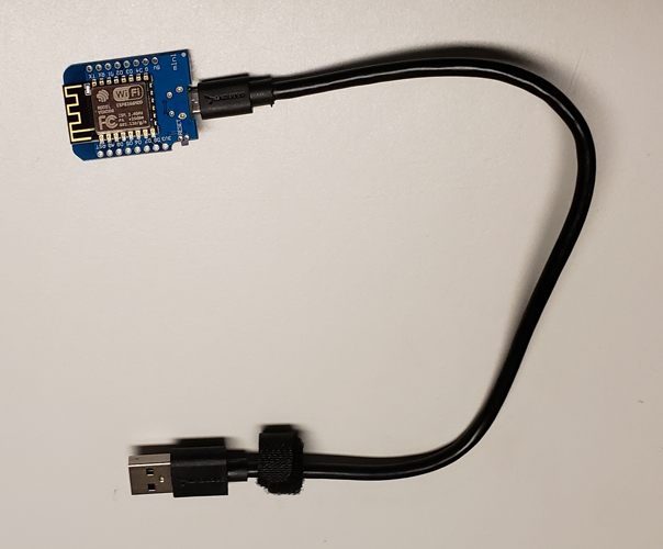
There are various versions of the mini NodeMCU but they all share an onboard 3.3 volt regulator, a USB<->serial conversion circuit, and the various other support circuitry so that they work right out of the box. The ESP8266-12 that they have onboard needs some pins tied high and others tied low before it will load software. It also needs a special "program" lead held high while reset is toggled. The NodeMCU package takes care of all of this for you. The version I use here is best documented at Wemos Electronics.
I use the Arduino IDE for ESP8266 development, so I just started my version 1.8.7 and selected the NodeMCU 1.0 as my target board. That let me look at the Examples and I found (under File>Examples>ESP8266WiFi) a "sketch" called Udp. I nabbed a little code from there and went into "software blacksmithing" mode. I heated it up and pounded on it a bit to beat it into my first test application.
All that application needed to do was:
1) connect to the WiFi network
2) get an IP address
3) display the IP address on the debug terminal
4) loop while
5) listening for UDP packets and displaying them
6) interpreting properly formatted packets and displaying the result
The result of this is called ESPlineUDP.ino and is the first program. Since this was only testing communication with the NodeMCU, I needed only to connect one to a USB port on my PC and proceed.
To send test UDP packets, I used a Linux system and the script sendudp.sh. That script is also in the program section, but is so short that it follows here:
cat bin/sendudp.sh <-- Linux command to display the script
#!/bin/bash -x
IP=192.168.95.107
# test sending UDP packet (only in bash)
echo -n "996,025" >/dev/udp/$IP/4949
sleep 3
echo -n "096,955" >/dev/udp/$IP/4949
sleep 3
echo -n "000,000" >/dev/udp/$IP/4949
Obviously, once an IP had been assigned to my NodeMCU, as determined
by monitoring the console, I had to change the IP addresses in this script before running it. The port number 4949 I pulled from the air but it needs to be the same in the script and in ESPLineUDP.ino.
Once that worked, I added LEDs in place of wheel motors and controlled their brightness with Pulse-width Modulation (PWM). If you don't know the term, Wikipedia explains it well.
https://en.wikipedia.org/wiki/Pulse-width_modulation
It was my plan to use PWM to control the speed of each wheel in the line-following robots. I regulated their maximum current with 91 ohm resistors. My LEDs drop 2V and run up to 20mA. I calculated resistors of 130 ohm for 10mA but found I was missing most values near there. Time to restock, but until then I found 91 ohm resistors for a maximum current of 14.3mA. Close enough. Since the ESP8266 should only drive 12mA as a source, I wired the LEDs to the 3V3 rail and used the ESP8266 to sink rather than source the drive current. Since the ESP8266 is rated to sink 20mA on multiple pins, that should be fine.
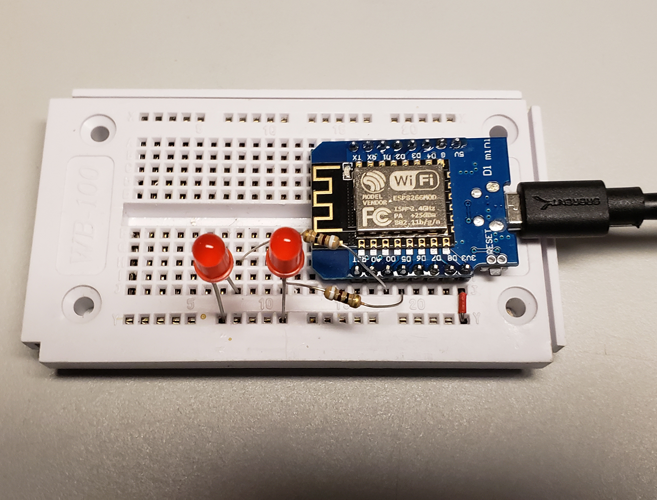
I soldered pins to my NodeMCU and placed the whole circuit on a 24 row breadboard. I used variables in the program to make changing pins easier, but I used GPIO16 and GPIO14 for the LEDs to be eventually motors. One more step complete. That program is called ESPLinePWM.ino.
A note on the breadboard wiring: There is a (red) jumper from the 3V3 output of the NodeMCU's voltage regulator to the + rail of the breadboard. The positive leads of both LEDs are plugged into this. The other LED leads are wired through the 91 ohm resistors to GPIO16 and GPIO14 to represent left and right motors. That's it!
A digression: What do I mean when I say "source" and "sink"? If you're clear on the concept, skip this paragraph. The obvious way to drive a LED is to provide a "1" level when you want the LED on and attach the other lead of the LED to ground (through the appropriate current limiting resistor). That works fine and with an ESP8266 you may do this for any load up to 12mA. This is using a current SOURCE. An alternate way of attaching a LED is to tie the other lead to the voltage source. This way when you provide a "1" level no current flows but when you provide a "0" level then current flows from the voltage source through the LED and into the port which SINKS the current. Remember, LEDs are polarized devices and you must turn them around to sink rather than source. The longer lead goes towards the source of the current.
Running a robot attached to my USB port would be inconvenient, to say the least. I need to find the IP address assigned to each robot when it powers up. To do that will take a small display.
I love the readability of small OLED displays and they are not too expensive. Some NodeMCU modules even come with them built-in but these were more expensive and harder to find. 128x64 pixel OLEDs are easy to drive because of extensive libraries available for the Arduino IDE. I like the U8g2lib.h, so that's what I've used.
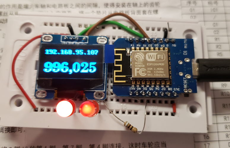
Physically, attaching the OLED is dead simple, too. It only takes four connections - VCC, GND, SDA (data), and SCL (clock). I used GPIO5 for the clock and GPIO4 for the data. The small display fits nicely on the same breadboard with the NodeMCU.
To be clear about the wiring, I added a black G jumper from the NodeMCU to the - rail of the breadboard. I used that rail and a black wire for the GND pin of the OLED. I used a red wire around the end of the OLED from the + rail to the VCC connection. The brown and green wires for the data and clock are mentioned above. The LED wiring didn't change. That's it!
Finding the right fonts and type sizes for the display takes a bit of trial and error, but in the end I was able to have a VERY readable display. I soon got it working (once I put my glasses on and found a displaced ground wire).
Note the sendudp.sh script above has sent a datagram that has been received and set the two GPIO ports to two different values. 996 corresponds to a pulse stream that results mostly high levels and 025 mostly low levels. Since I'm sinking the current rather than sourcing it (see digression above), I reverse the signals in the program and it all works out.
This program is doing everything that the final version needs to, so it gets the final name in the series - ESPLineMouse.ino. It will be tweaked, but if the design doesn't change in any major way, it is DONE.
Now that I can control the LED brightness with UDP datagrams sent from my PC (and other sources), I'm ready for the robot.
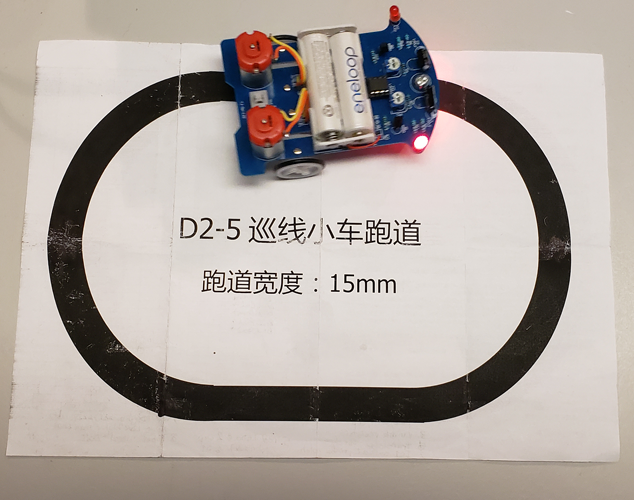
How do I pick out the one that is easiest to modify? After searching the web, I found one. The D2-5 Intelligent Tracking Car, with this wiring diagram from the website of ICStation.com.
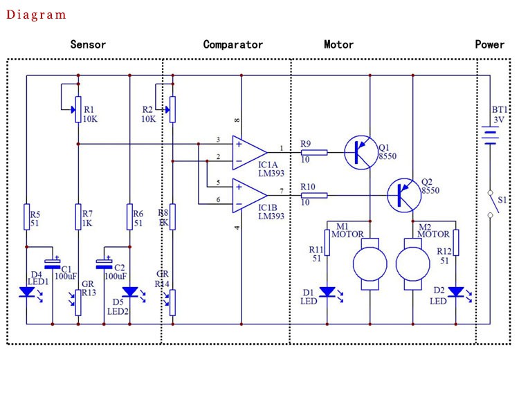
What I notice is a simple circuit that the one IC has connections for everything that I need. There is power, ground, and control of the two transistors that run the motors. In addition, it is available from LOTS of sources. That makes the best prices for 10 units pretty inexpensive, less than $60 with shipping. Okay, I'll order a dozen. Final cost from ICStation is $67.08.
As it happens, I looked in my box of soldering kits for my grand kids and found one right there. It MUST be fate.
The downside is that the instructions are in what I think is Chinese. The characters are ideograms, anyway. The upside is that the pcb is plainly silk screened with component placement including orientation, where applicable. That's just fine.
I used the standard technique of putting in the shortest components first, then the next taller ones, then the next taller ones. I know four band resistor codes by heart (Big Boys Race Our Young Girls But Violet Generally Wins, or something like that) but I had to use an app for these five band resistors. Not too difficult. The color values are the same, just the place values are different. Now I know THOSE rules. I later found GREAT instructions for assembly in English but my car was already running perfectly.
Assembly instructions in English
With a little adjustment, it ran fine and followed the circle that I found on the back of the instructions.
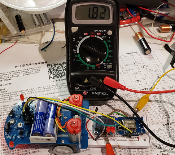
 Now to combine the two projects. I removed the IC1 from its socket. I put some header pins into the socket and attached my breadboarded circuit. I turned on the robot and GOT NOTHING. My theory was that I had too little voltage reaching my NodeMCU from the very old NiMH cells I was using in the line follower. I whipped out my VOM and found only 1.8V at the breadboard. Truly not enough.
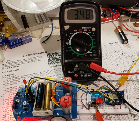
I'm a big fan of rechargeable cells. My next attempt was a Lithium Ion rechargeable cell commonly called a 10440. They are nominally 3.7V and are capable of high current when needed. When I purchase these, I carefully search out PROTECTED cells for my general use. These are a little longer than a standard AAA cell (2mm-3mm) because there is a circuit stuck on the end that protects them from over and under-charging and over-current. These are GREAT for experimenters.
I stuck one in the AA socket and added a dummy in the other AA socket to complete the circuit. (If you don't have a dummy AA, just use a bolt of the right length). This time I measured 3.5V and the NodeMCU fired right up and connected to my WiFi.
 I don't HAVE 10 of the 10440s however and don't want to buy more of these expensive beasts right now. I tried the normal person's solution (sometimes I can pass when you don't look too closely). I tried AA alkaline cells, got 2.7V at the breadboard, and again the NodeMCU connected to the WiFi successfully.
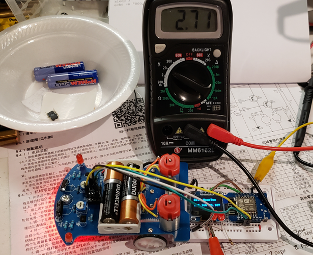
I'm left with three practical choices: alkaline cells, more 10440s, or replacing the battery holder with a 3-cell variety to use with my NiMH. Given these choices, alkaline cells are an easy win. After all, I want everyone to enjoy their robots after our week together when the take them home and I'm NOT giving away all my rechargable cells. However, taking them home will cause more problems later.
Now I've got the circuit attached to the car. When I try the script, the wheels turn as hoped and stop when 000,000 is sent but small numbers don't produce slow motion - they produce noise instead. I may need to just stay away from them.
Editing my sendudp script for the IP address and then running it to control the car is not much fun. Time to send my commands another way.
I investigate the MIT App Inventor but the learning curve seems steep. I come up with the idea of a touch-to-move web page. I'll try than next.
First I need a web server. Apache is a good choice and I've used it before. I've got a Raspberry Pi in my network monitoring the temperature of my living room. That might seem stupid but sometimes we're away in the winter and it will send me a text if the temperature dips below 50 degrees. I'll have time to respond before something REALLY bad happens. That doesn't seem so stupid.
Re-purposing the Pi seems a good choice. Taking it to the lake for a week in the summer is easy. I log in as root and install Apache2 with "apt-get install apache2". I then edit /etc/apache2/sites-enabled/000-default.conf to allow server-side scripting (called CGI) and add a couple other options that I like. I'm older than you but can't easily do the CGI in FORTRAN, so I install Perl CGI help with "apt-get install libapache2-mod-perl2" then enable CGI with "a2enmod cgi cgid". I'll test everything with my printenv.cgi test script.
A word about server-side scripts. Today the trend is client-side scripting for almost everything. Because of this, Javascript is one of today's top languages. This makes sense for many things. If you have hundreds or thousands of clients connecting, getting them to do as much of the work as possible is a good idea. Like many good ideas, it is often taken too far and last year's laptop can't keep up with the demands today's fancy sites.
For my application, server-side seems better. Some tablets and phones we'll use are OLD. A simple web page won't overtax them but I don't want to add more.
My web plan - mouse.html: It will display a picture in the browser. I'm using a smiley face. It will process touches on the picture using an image map. The closer to the top of the image, the bigger numbers I send to the robot. A touch off to the side slows the corresponding wheel to force a turn in that direction. Then the same page redisplayed to await the next touch. The CGI script sendudp.cgi is called by mouse.html to accomplish this. Right now, the target IP address is hard coded in sendudp.cgi. This HAS to change but I have yet to decide on HOW to store and retrieve the correct address to match each message with the correct mouse.