ardublock.xml
- add block genus
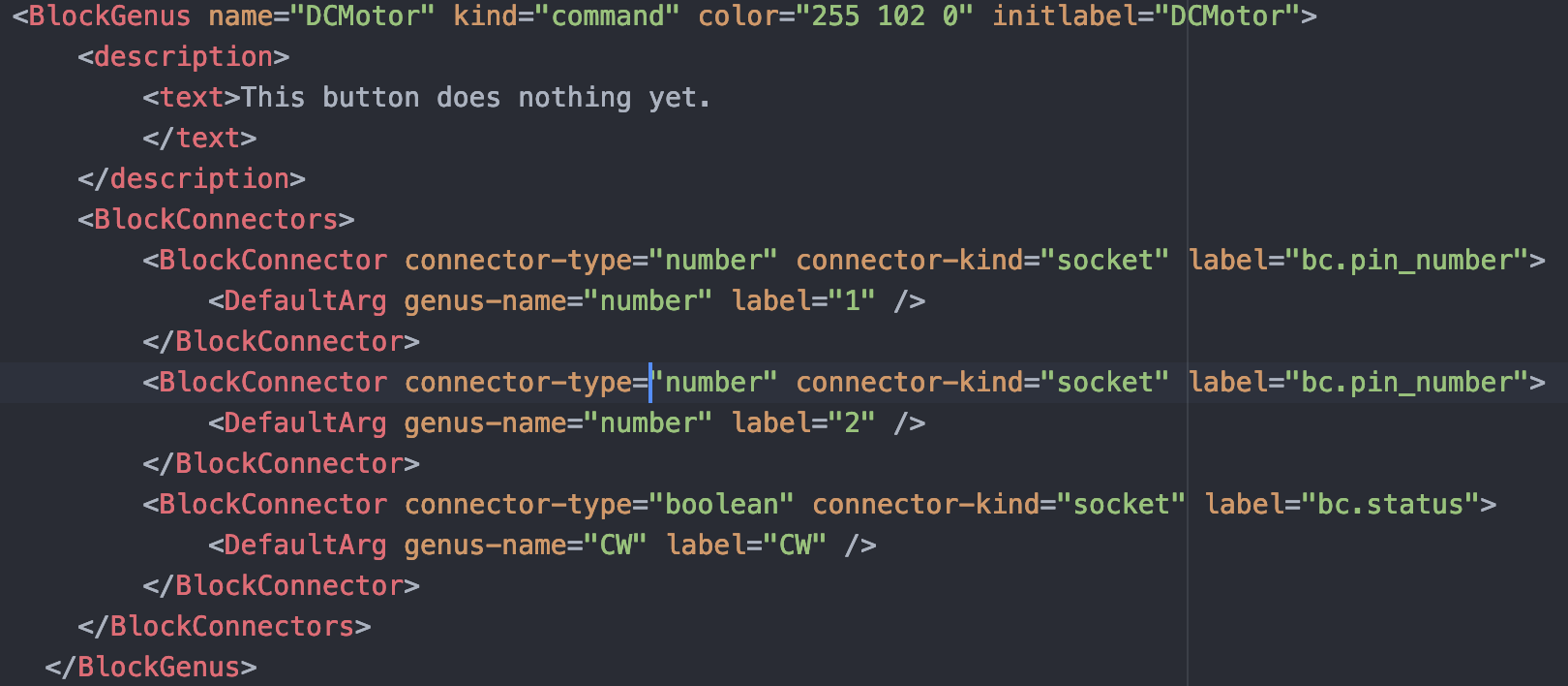
The block genus "initializes" the block. It determines the block's physical form and what it can connect to.
The four options, CW, CCW, ISTOP and RSTOP are all their own block as well which must be added.

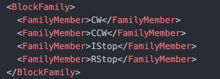
- add block family
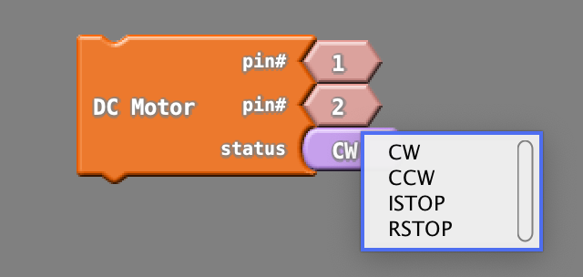
Since CW, CCW, ISTOP and RSTOP are related options, they must be placed in the same block family. This allows them to be included together in the same drop down menu as shown above.
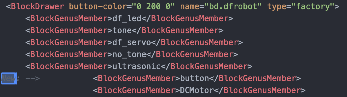
- add block genus to block drawer
The blocks should be added to the corresponding block drawer. This is the "folder" the blocks are located within arduBlock.
-----------------
- connect block genus to path of block java file
-----------------
- add block label
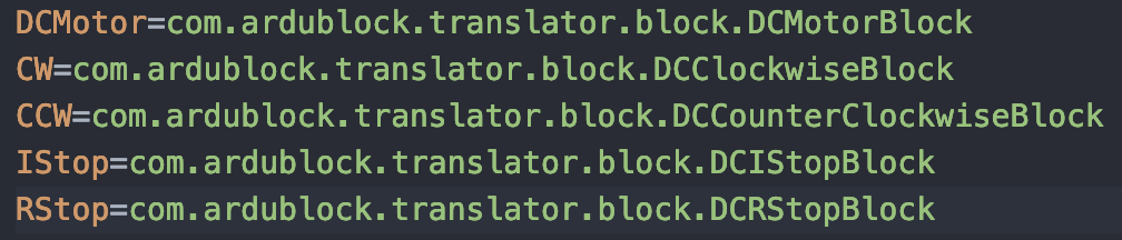
bg.CW=CW
bg.CCW=CCW
bg.IStop=ISTOP
bg.RStop=RSTOP
- add block description
bg.DCMotor.description=DC motor control
bg.CW.description=Turns motor clockwise
bg.CCW.description=Turns motor counter-clockwise
bg.IStop.description=Instantly stops motor
bg.RStop.description=Gradually stops motor
-----------------
This is the java file: DCMotorBlock.java
package com.ardublock.translator.block;

import com.ardublock.translator.Translator;
import com.ardublock.translator.block.exception.SocketNullException;
import com.ardublock.translator.block.exception.SubroutineNotDeclaredException;

public class DCMotorBlock extends TranslatorBlock
{
    public DCMotorBlock(Long blockId, Translator translator, String codePrefix,    String codeSuffix, String label)
    {
        super(blockId, translator, codePrefix, codeSuffix, label);
    }

  @Override
    public String toCode() throws SocketNullException, SubroutineNotDeclaredException
    {
      TranslatorBlock pinBlock0 = this.getRequiredTranslatorBlockAtSocket(0);
      NumberBlock pinNumberBlock0 = (NumberBlock)pinBlock0;

      String pinNumber0 = pinNumberBlock0.toCode();
      translator.addSetupCommand("pinMode(" + pinNumber0 + ", OUTPUT);");

      TranslatorBlock pinBlock1 = this.getRequiredTranslatorBlockAtSocket(1);
      NumberBlock pinNumberBlock1 = (NumberBlock)pinBlock1;

      String pinNumber1 = pinNumberBlock1.toCode();
      translator.addSetupCommand("pinMode(" + pinNumber1 + ", OUTPUT);");

  		TranslatorBlock rotation = this.getRequiredTranslatorBlockAtSocket(2);

      String pinControl = rotation.toCode();

      String ret;

      if (pinControl.equals("CW") == true)
      {
        ret = "\tdigitalWrite(" + pinBlock0.toCode() + ", HIGH); \n\tdigitalWrite(" + pinBlock1.toCode() + ", LOW); \n";
      }
      else if (pinControl.equals("CCW") == true)
      {
        ret = "\tdigitalWrite(" + pinBlock0.toCode() + ", LOW); \n\tdigitalWrite(" + pinBlock1.toCode() + ", HIGH); \n";
      }
      else if (pinControl.equals("IStop") == true)
      {
        ret = "\tdigitalWrite(" + pinBlock0.toCode() + ", HIGH); \n\tdigitalWrite(" + pinBlock1.toCode() + ", HIGH); \n";
      }
      else
      {
        ret = "\tdigitalWrite(" + pinBlock0.toCode() + ", LOW); \n\tdigitalWrite(" + pinBlock1.toCode() + ", LOW); \n";
      }

      return ret;
    }

}
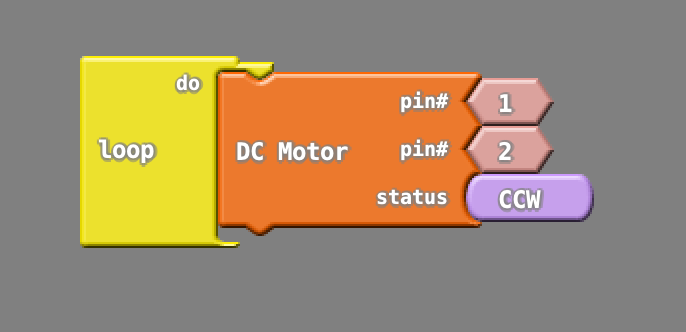
The idea is to read in the clockwise, counter-clockwise, instant stop, or ramp stop parameter and set the pins accordingly. Each parameter corresponds to a unique combination of 2 pins being on or off (4 total combinations).
Output and what the block looks like:
void setup()
{
  pinMode(1, OUTPUT);
  pinMode(2, OUTPUT);
}

void loop()
{
  digitalWrite(1, HIGH);
  digitalWrite(2, LOW);
}
Discussions
Become a Hackaday.io Member
Create an account to leave a comment. Already have an account? Log In.