Sponsor Link:
UTSource.net Reviews
It is a trustworthy website for ordering electronic components with cheap price and excellent quality.
Setting this module up for use
Before you can even start charging devices and using all the functions of this module, you will need to solder some things to this module, which will all be described in the simple step below: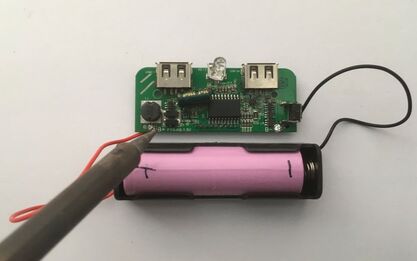
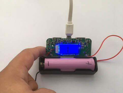
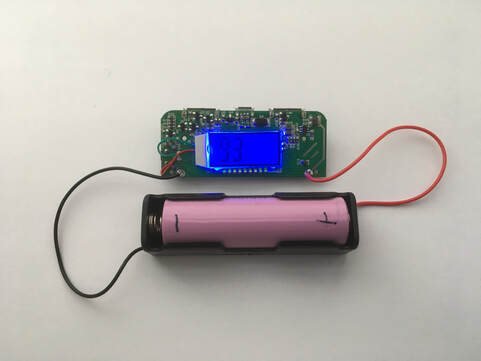
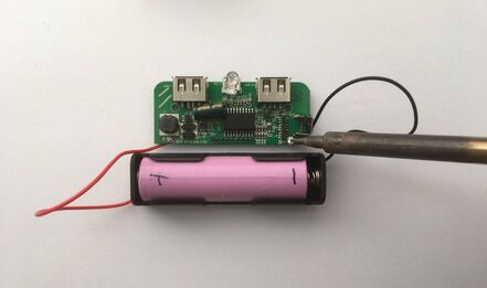 1. When receiving your module right out of the package, you will need to solder a 18650 lithium-ion cell to the module since this module will be charging the battery, then using the battery's charge to power up devices through the module's USB output ports. I would recommend getting a 18650 cell holder to solder onto the module, as it will be easier than soldering wires to the battery itself, as seen in the picture. You can even solder more than one 18650 battery. However, make sure no power is is connected to the module upon soldering and make sure you are soldering the battery connections in the correct polarity on the module, as clearly labeled on the module's PCB.
Charging it up
Now, you have already soldered lithium-ion batteries to the module and the only thing which you will have to do with them is to start by charging them! From this stage, the charge fed into the batteries will be taken out to charge other devices, but those steps will be described in the section after this. However, the following steps below will show you how to charge the batteries which you have already soldered onto the charger:
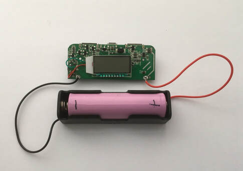 1. Flip the module onto its face (LCD display facing up) and make sure no loads are connected to any of the two USB output ports (Type A Female ports). Your battery should already be soldered onto the module, whether it is through a battery holder or simply through wires connecting batteries to the module.
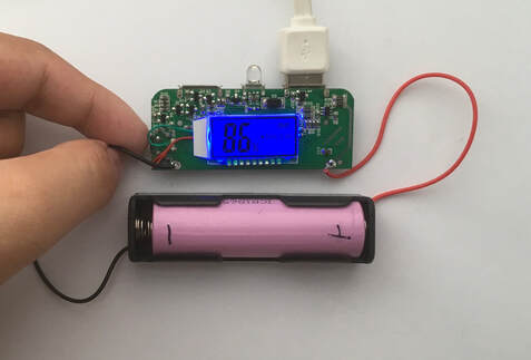
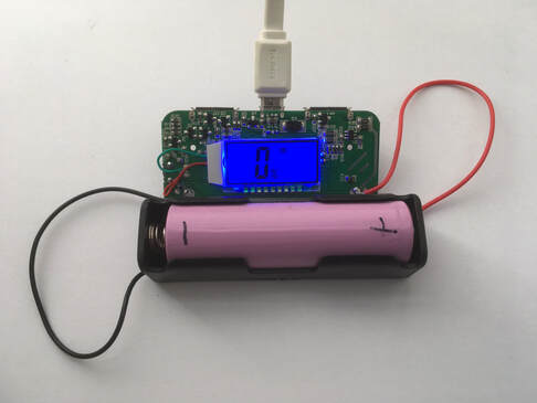 2. Now, insert a male micro-USB power cable to the female micro-USB port located in the middle of the module. This is where the input power will be fed in to the buck converter circuit to ultimately charge the batteries. Around +5 volts will be fed in from your micro-USB cable input, which will be bucked down to around +4.2 volts, which is an ideal voltage to charge 18650 lithium-ion cells. The LCD display should turn on immediately, displaying the percentage of your battery from a scale of 0% - 100%, indicating how much charge your battery needs until it is fully charged. You should also see the text "IN" on the display, telling you that you are charging the battery and inputting power in to the module.
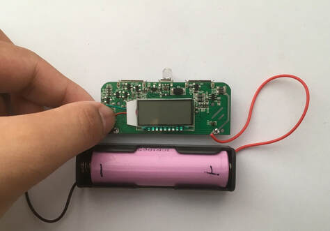
 3. Occasionally, after a while when charging the battery, the LCD display backlight will be switched off, and you can turn it back on again by pressing the button to the right of the module once. The LCD backlight should switch on for a couple of seconds before turning off once again. The backlight is perfect for low light conditions.
 4. Once your battery capacity percentage reaches 100%, the battery will be fully charged and ready to be drained out to output devices, which will be drawing current from the battery. You can now remove the male micro-USB power cable, which is the input for supplying the charge, from the module. Let's move on to the next section to see how you can now discharge the battery to power devices!
Powering devices up
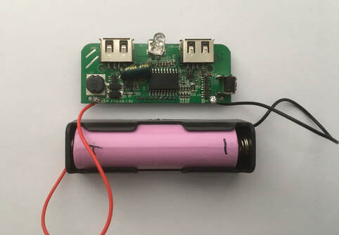
Now that your batteries are fully charged to its maximum capacity, you can now discharge them to other devices needing charge, like mobile phones, USB flashlights or portable radios. This module features two USB Type A Female output ports, which draws two separate currents for powering up different modules. We will show you how to power loads with this module with the steps below:
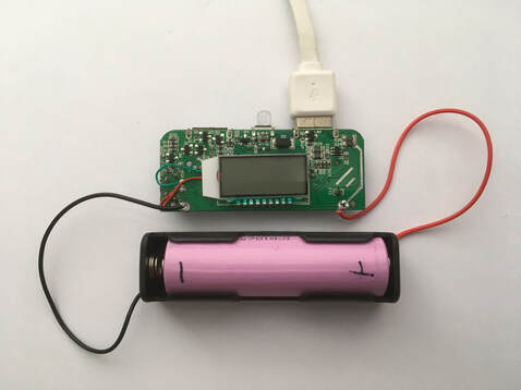
 1. Make sure you remove your input male micro-USB power cable before connecting any Type A Male USB cables for output power. You can plug in a cable to the 1 amp or 2.1 amp USB output port as labelled on the PCB. The image above shows both ports being used with the LCD display also showing information about which USB output ports are being operated.
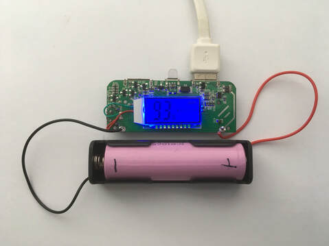 2. Then, as soon as your load is plugged in to either or both of the USB output ports, the LCD display will light up to display your battery capacity again, and as your load is being powered, the battery capacity percentage will gradually decrease to 0%. You will also see the text "OUT" on the LCD display, indicating that you are outputting power from the battery to your load. When selecting which USB output port to use, it all depends on the output device and how much current it draws, so I recommend looking at your device's power specifications to match its current draw with the right USB output port on this module.
 3. Occasionally, after a while when charging a device, the LCD display's backlight will be switched off, you can turn it back on again by pressing the button to the right of the module once. The LCD backlight should switch on for a couple of seconds before turning off once again. This is perfect for low light conditions.
 4. Once your battery is fully discharged, the module and LCD display will automatically switch off as your load is not being charged anymore. Unplug your Type A Male USB cables going to one or both of the USB output ports and insert a male micro-USB power cable as you will now have to repeat the process of charging the battery again. The bigger the battery capacity you have, the more charge it can hold to power devices for longer periods of time.
Turning on the flashlight
This module also has an additional flashlight function, which essentially is an ultra bright white LED for lighting up small things in dark conditions. It is fairly easy to turn on as you will see in the simple steps below:
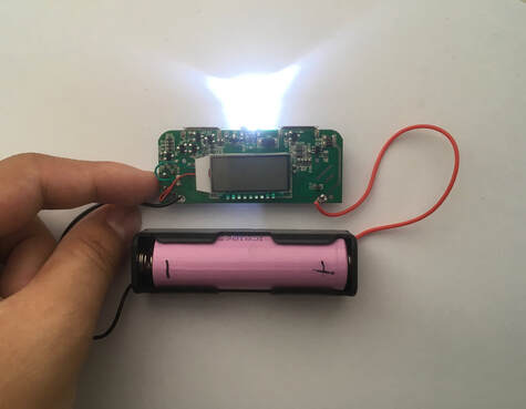 1. At anytime when you want to turn on the LED, make sure you have a battery connected to the module. Then double press the button to the side of the module. You will see the LED instantly light up. You will need to at least have some charge in the battery to power up the LED as a flat battery won't be of any use.
 2. Double press the same button again to turn off the LED.
Conclusion
ICStation's Dual USB Mobile Battery Charger can be greatly used when making portable power banks, solar chargers or when being used as an emergency backup power supply. In my opinion, the incorporation of the dual USB outputs and LCD display truly can help a user to charge multiple devices simultaneously while monitoring your battery's decreasing or increasing capacity. Nevertheless, the ability for this module to charge batteries with any capacity makes this useful when making an emergency charger, where as much charge as possible is needed. This module's ease is great for someone who is not into electronics as one can easily operate this module without having hardware or software knowledge. Furthermore, this charger's price is also very affordable as this module is just under $5 ($4.85) and I think that it is very worthy for what this charger can do. All in all, I would recommend this module if you have intentions of creating some kind of emergency battery storage project, portable mobile charger or power bank.
Amazing opportunities
Also, be sure to check out PCBWay, a leading manufacturer and distributor in PCB design and manufacturing. They have amazing prices and excellent quality in their services, so don't miss out on them! Plus, PCBWay has an amazing website, online Gerber viewer function and a gift shop so make sure to check out their links below:
PCBWay Free Online Gerber Viewer Function: https://www.pcbway.com/project/OnlineGerberViewer.html
PCBWay Gift Shop: https://www.pcbway.com/projects/gifts.html
Make sure you check out the review for this product by clicking here.
Enjoy! Contact us for any inquiries!