mevlüt furkan demir
4 Panasonic / Sanyo CGR18650CG 2200 mAh LI-ion batteries were used to power the motor drive and arduino. One battery provides a rated voltage of 3.6 volts. Batteries are connected to each other in series and 14.4 volt voltage is provided. However, this 14.4 volt voltage is too high for the dc motor of the servo, which can damage the motor. Using the LM7812 regulator integrated voltage, the drive and arduino are powered by reducing the voltage to 12 volts.
Panasonic / Sanyo CGR18650CG 2200 mAh LI-ion 4 batteries connected in series. The positive (+) terminal of the batteries is connected to the 1st leg of the LM7812 regulator integrated. The negative (-) pole of the batteries to the second leg of the Arduino and the GND of the modular driver board are connected to the cable. On the third leg, the Vcc pin of the modular driver board is connected to the Arduino's Vin pin via a cable.
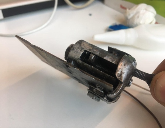
Gear Transmission System Design
17 mm inner diameter 22 mm outer diameter 30 mm length of the iron pipe in the upper part of the lathe 20 mm to 6 mm depth of the bearing was made to widen the bearing. 20 mm outer diameter 6 mm core diameter bearing ball is fixed. A two-mm wide and 20-mm long slit was opened on both sides of the pipe. In this way, the rotation movement of the nut is prevented and therefore it moves axially (longitudinally). The 2 mm thick sheet is cut as shown in figure 4 and punched at the midpoint. The hole is made of 6 metric taps with a nut suitable for the bolt. The nut is drilled with a 1.5 mm crochet hook from the point shown in figure 3. The wire is fixed to the nut through the hole. 6 metric 50 mm long allen head bolts were installed in the ball hub, the bolt was inserted through the bearing and secured with 6 metric nuts on the inside to prevent axial movement. The nut that we have made from the sheet metal is tightened to the screw and the nut is provided to move axially. The output shaft of the servo motor is turned into a hexagonal form with a diameter of 5 mm and it is mounted on the head of the bolt, so that the torque of the motor is transferred to the bolt. By shifting the bolt, the gear change is provided by hanging the gear wire with the axial movement of the nut. Thanks to the gas welding on the outer surface of the bolt head, two mutually tailstock was thrown to form a stigma. The switch was mounted in front of the dunes.
Servo Motor Blog
Some modifications have been made to the servo motor to drive the transmission system. In order to rotate the motor 360 degrees, the limiting pin on the power transmission gear in the gear unit was cut with the help of flex. The potentiometer connected to the same gear was also removed. The motor is supplied with 12 volts power and the drive circuit inside the servo motor is removed for a more powerful and faster operation. The output shaft of the servo motor was grinded and assembled into a 5mm hexagonal form to fit into the 6 metric allen head bolt.
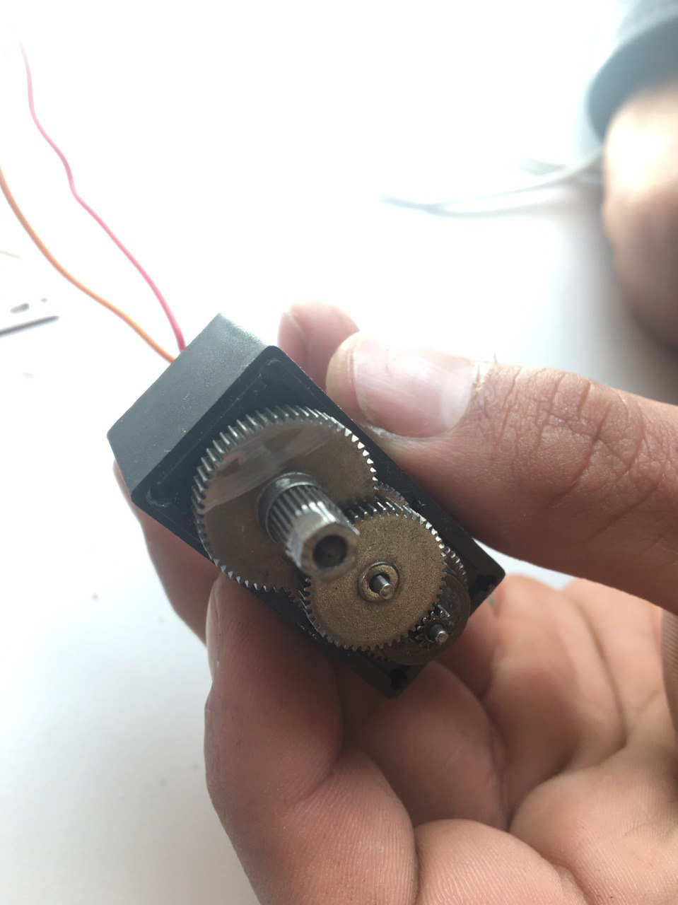
Figure 1. Servo Motor Gearbox
Servo Motor Modification
The four screws on the back cover of the MG996R servo motor were removed. With the help of the soldering iron, the motor drive was removed from the dc motor and potentiometer. Reducer cover opened. Power transmission gear was removed and the limiting pin on it was cut with the help of flex. The end of the gear was ground to 5mm hexagon shape. The gear unit is reinstalled and the gear unit cover is closed. After soldering the cables to the motor with the help of a soldering iron, the back cover of the servo motor was closed with screws.
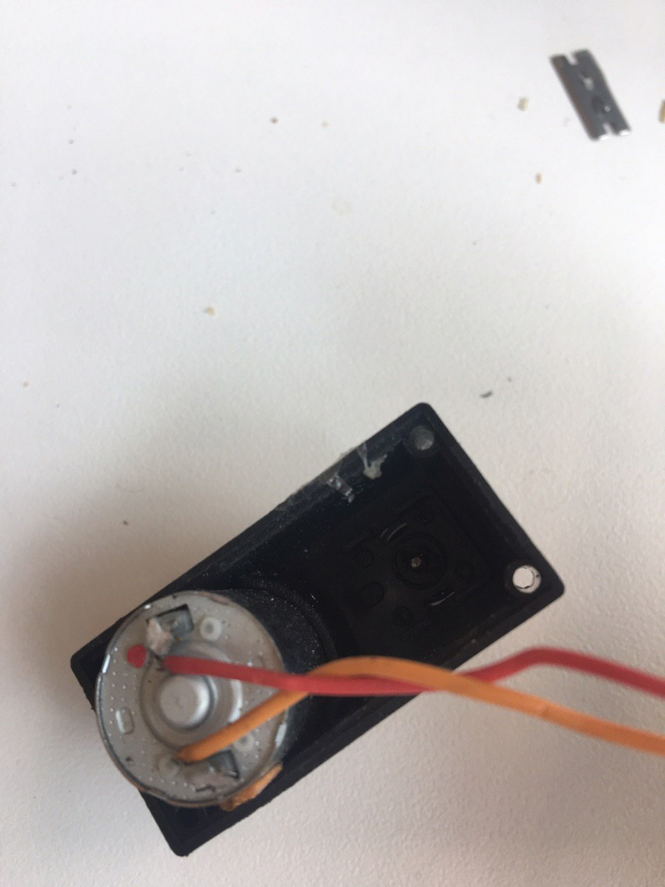
Figure 2. Servo Motor Modification
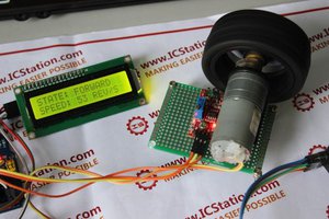
Screen Block
A “16 * 2 LCD” display is used to show the driver shifts, mode changes, speed and current gear status. The GND pin on the display modular board will be connected to the “GND” pin of the arduino, the CC VCC ”pin to the“ 5V ”pin of the arduino, the“ SDA ”pin to the du A5”...
 icstation
 Ozan Enginoglu
 Laura
Laura