 MagicWolfi
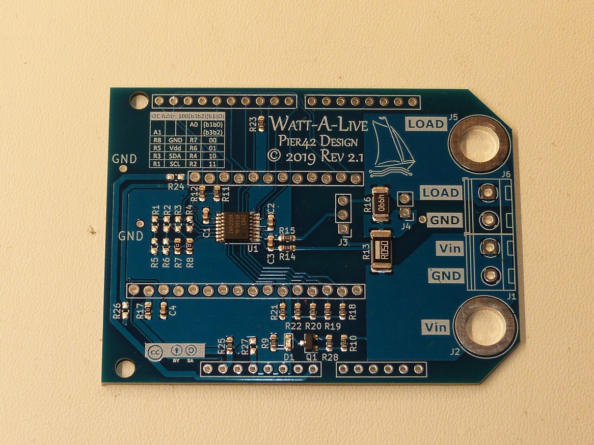
The board enables a wider variety of features compared to the standard INA219 solutions with 2 screw terminals. Most importantly it has 2 dedicated screw terminals for GND connection to measure the bus voltage and power. No need to solder the GND wire somewhere to the breakout board. It also has 16 selectable slave addresses, so multiple units can be used at the same time. And it has additional signalling pins for bus or shunt voltage and power alerts and warnings. It can be used as Feather Wing, Arduino Shield, as breakout board or on a breadboard.
Full feature set:
- Adafruit Feather Wing and Arduino Uno Shield connector option
- Current monitor with 2 different ranges for high current and sleep mode low current measurements
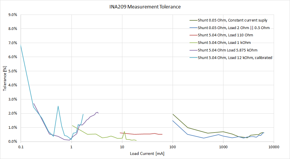
- Rev 2: 0.05 Ohm shunt to measure 6.4A to 200µA. 4.99 Ohm shunt can be added for a current range of 58mA to 2uA (theoretical minimum).
- Realistically the overall range is 6.4A to 1mA measured or 200uA calibrated with 2% error.
- Positive and negative current flow
- Bus voltage and power monitor with 2 dedicated GND terminals
- Communication interface: I2C up to 3.4MHz
- 16 I2C addresses selectable through resistor options
- 6 dedicated signaling pins (SMBus Alert, Warning, Overlimit, Critical, Convert and 1 GPIO)
- Operating supply voltage 3.0V to 5.5V
- Optional 4mm Banana plugs for high current feed or bypass
- Size: 71mm x 54mm (2.8" x 2.1")

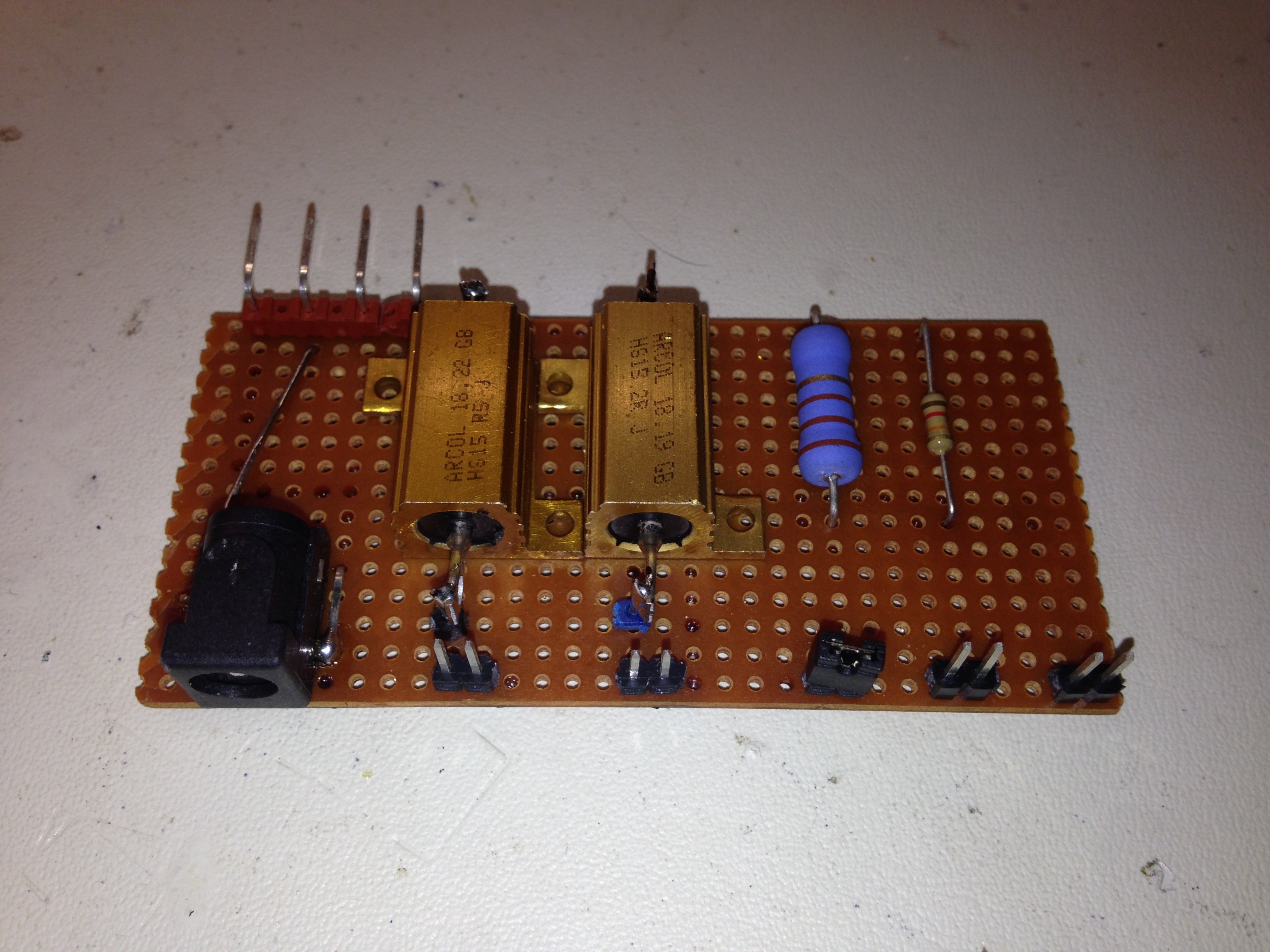 The resistor values are 0.5 Ohm, 2 Ohm, 110 Ohm, 12 kOhm and 10 MOhm (still missing :( ) for a full range of current settings. They can all be selected by jumpers.
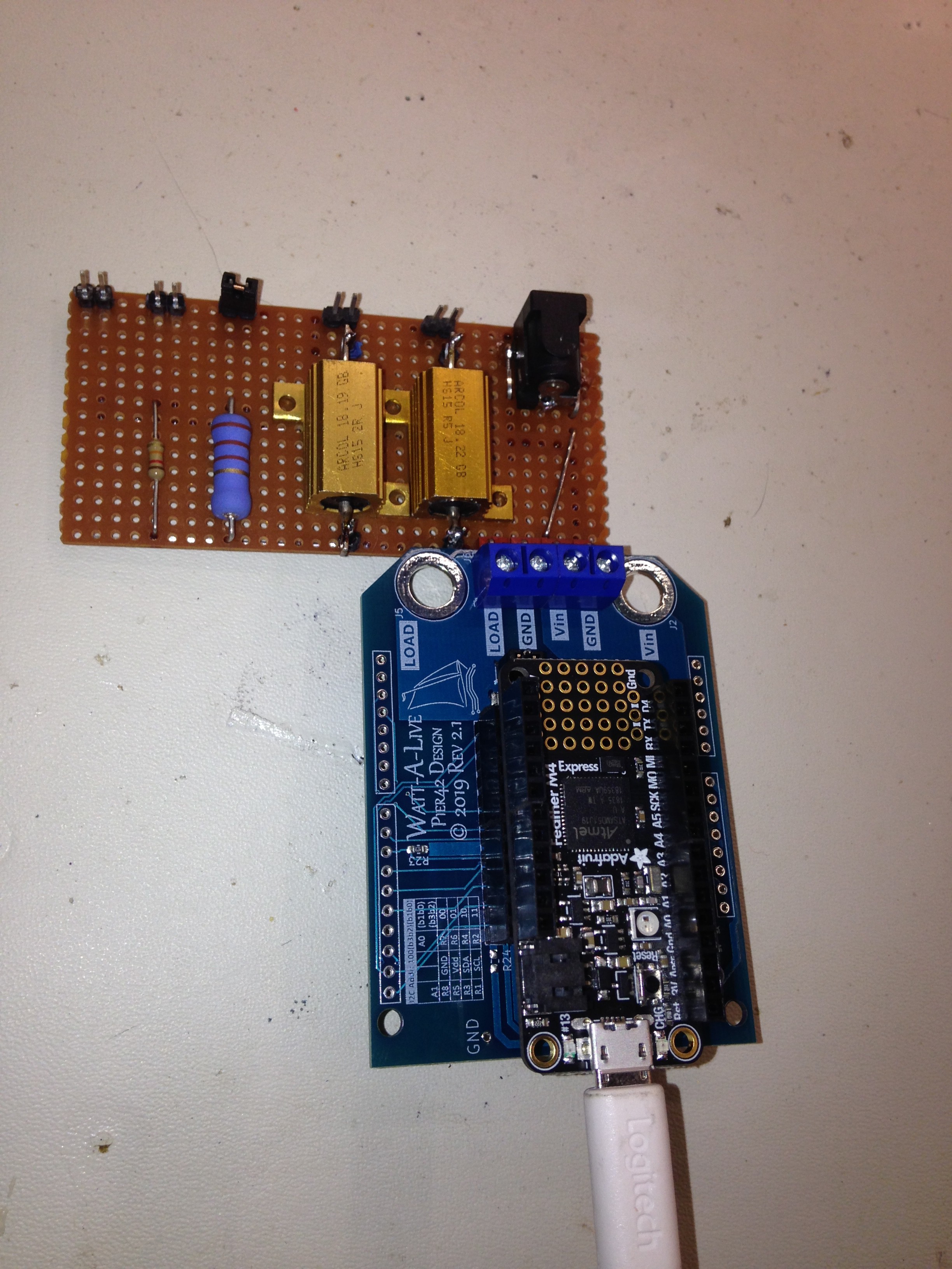
 bhaskar.anil430
 John Loeffler
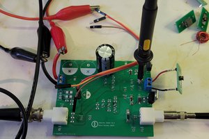
 Kevin Kessler
 Lithium ION