0%
0%
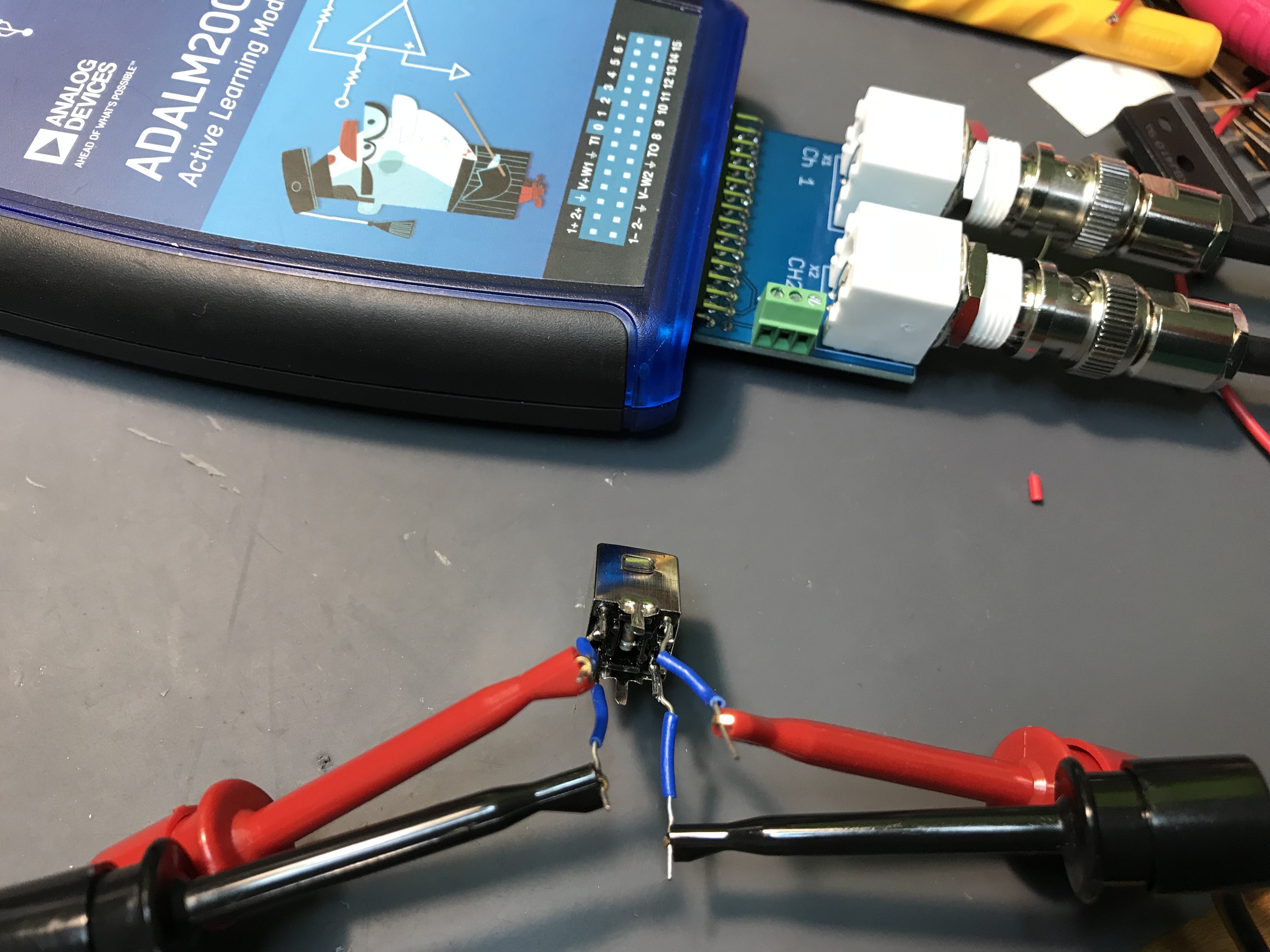
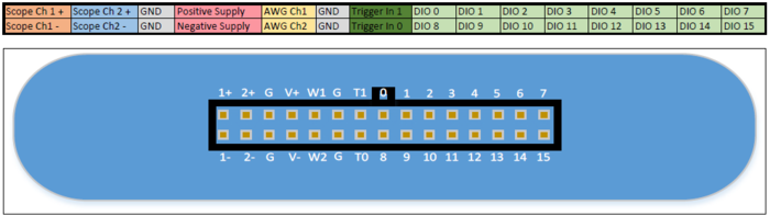
How to handle ADALM2000?
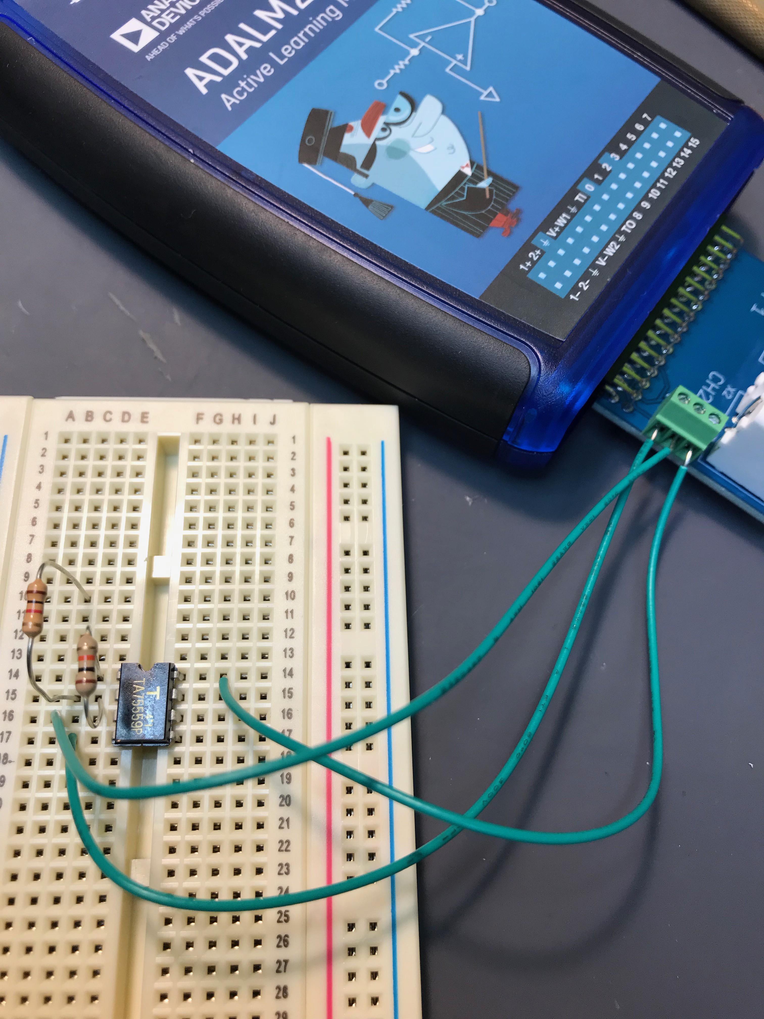
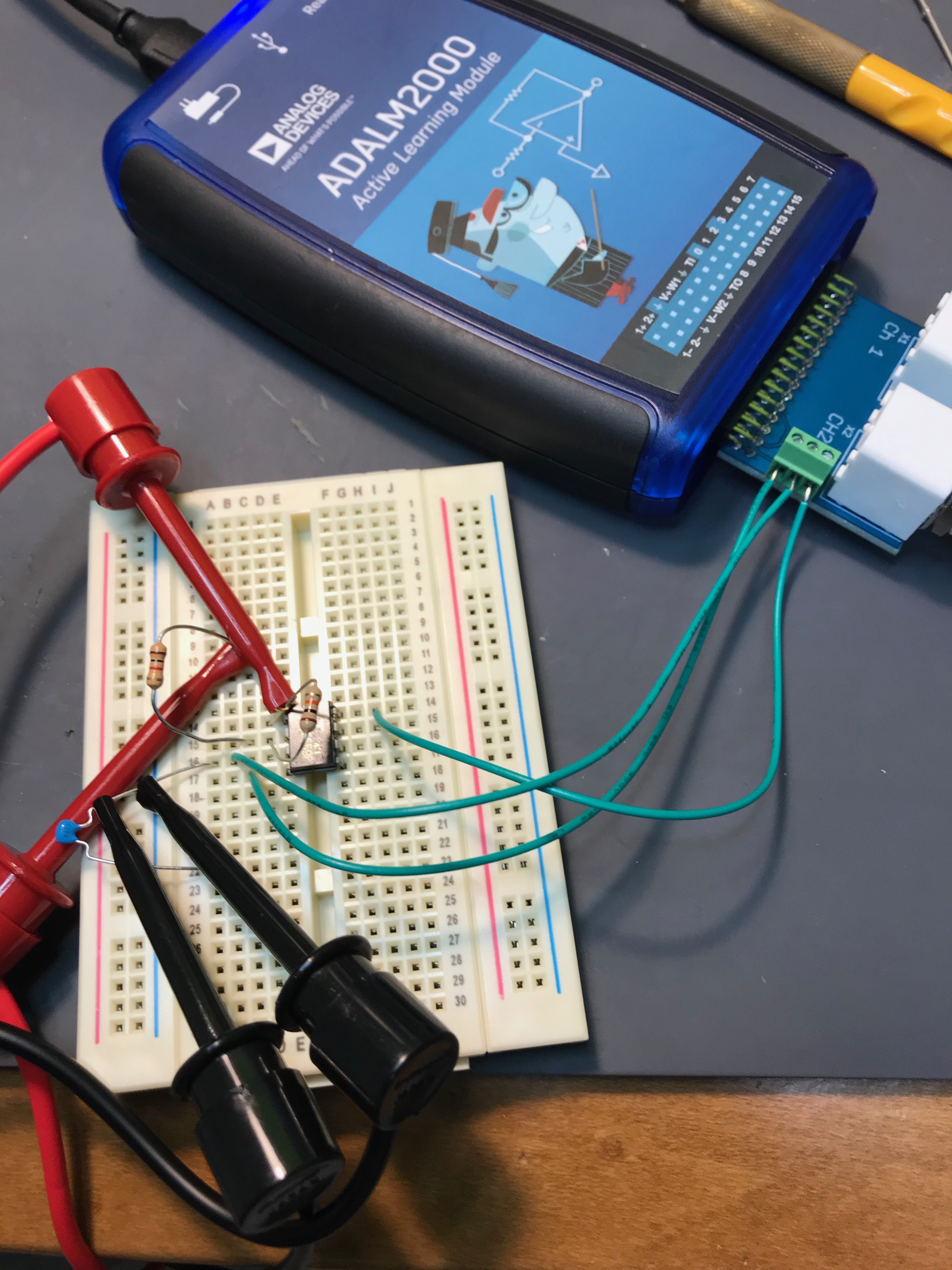
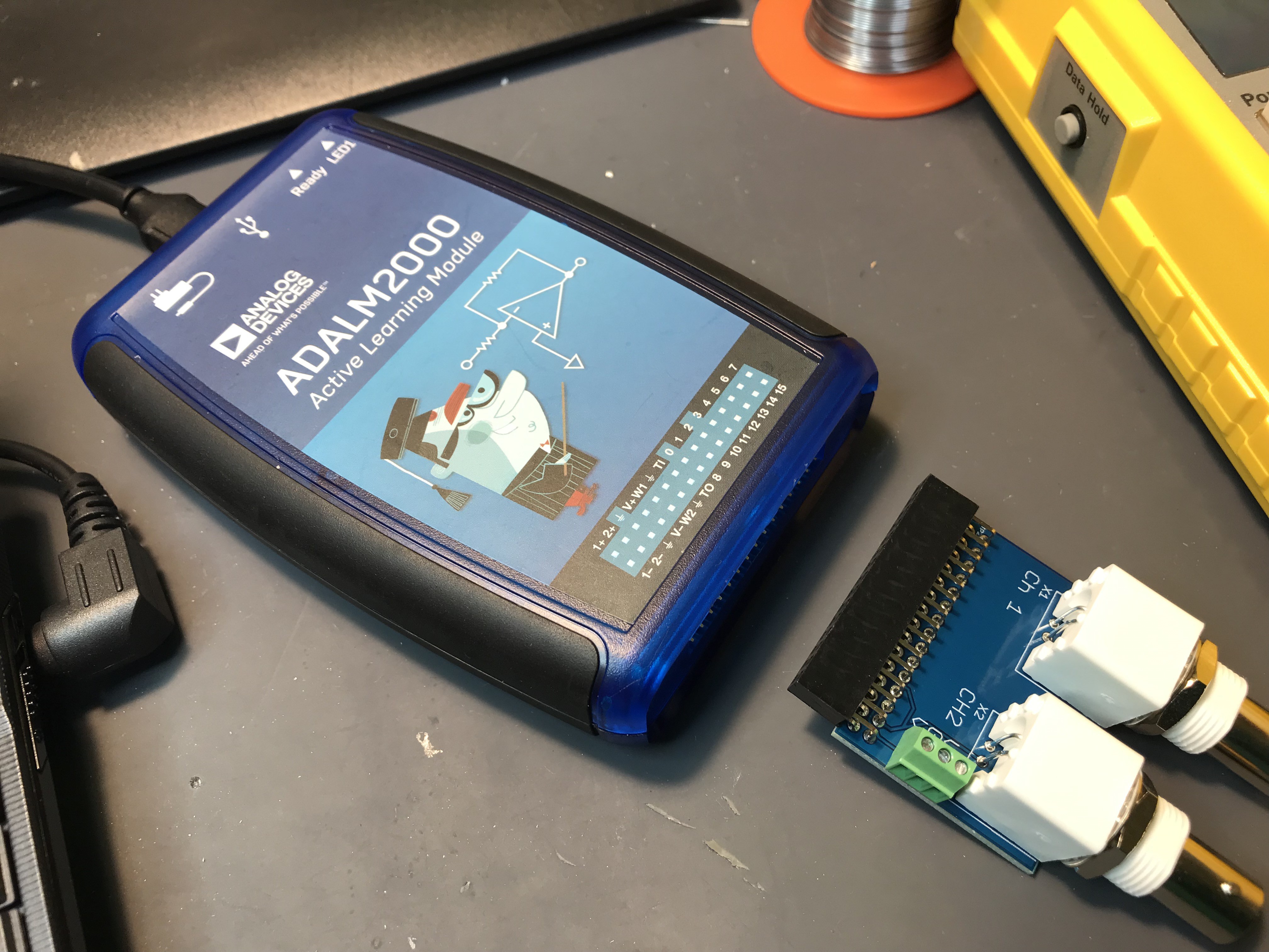
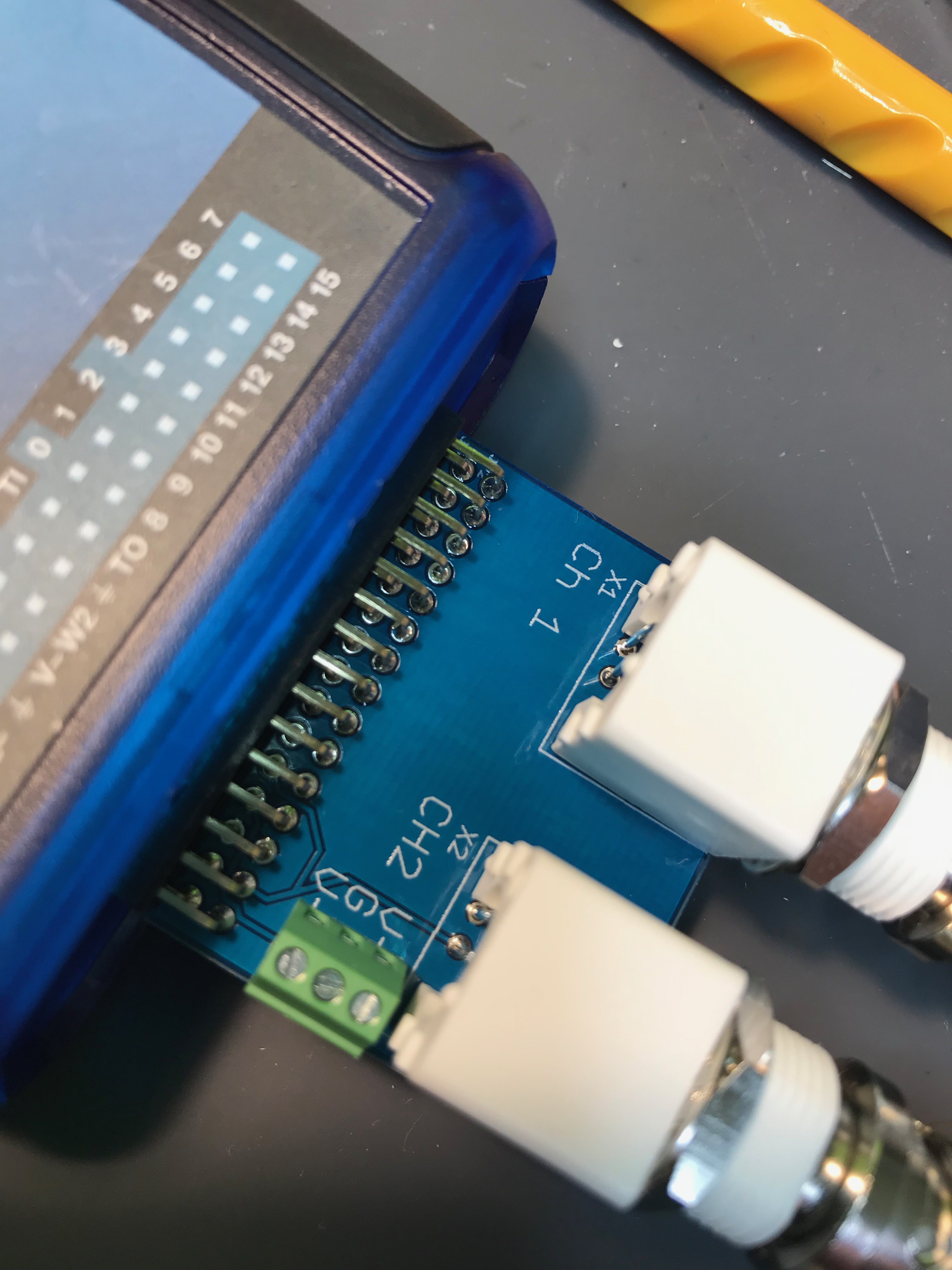
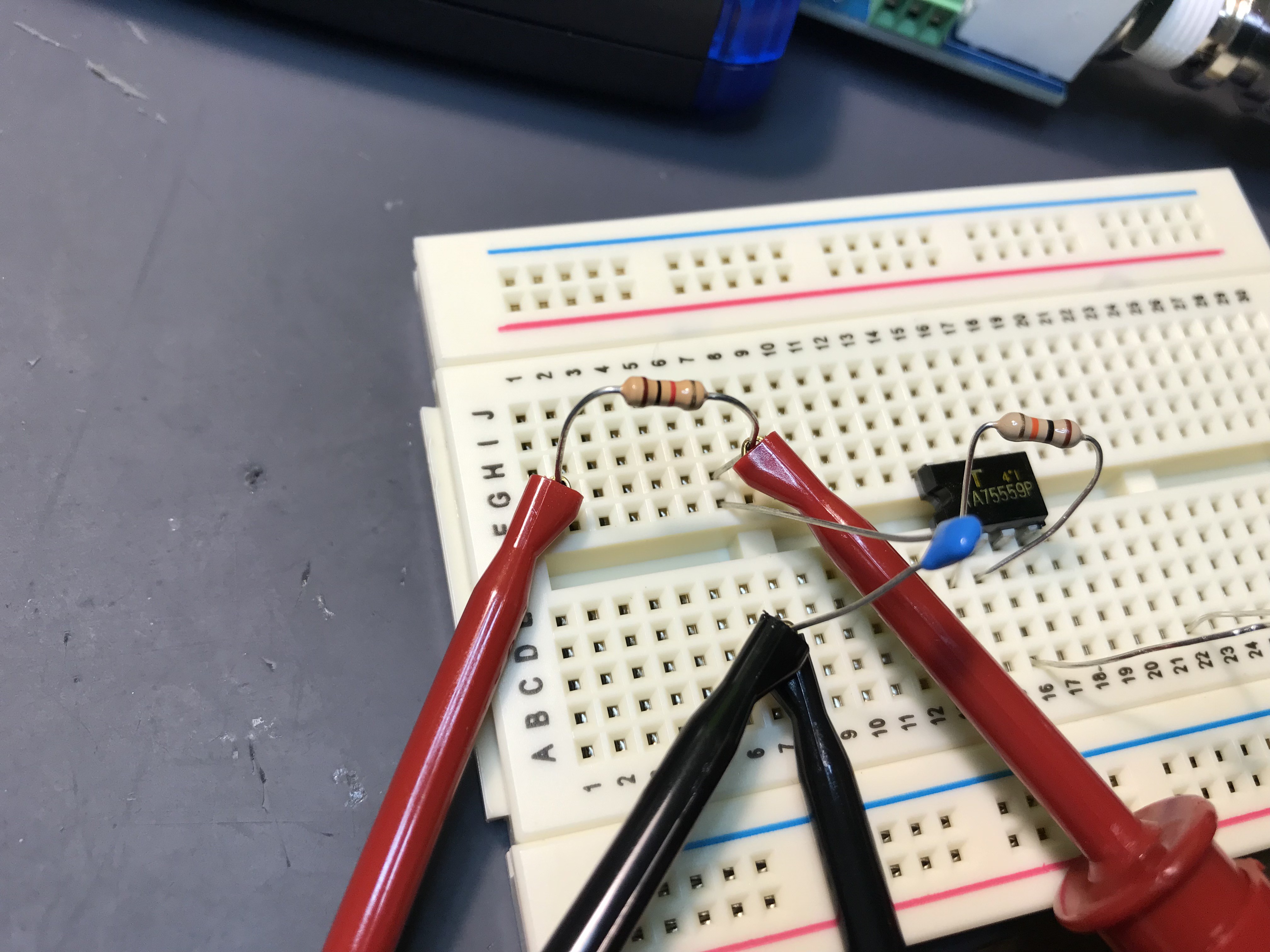
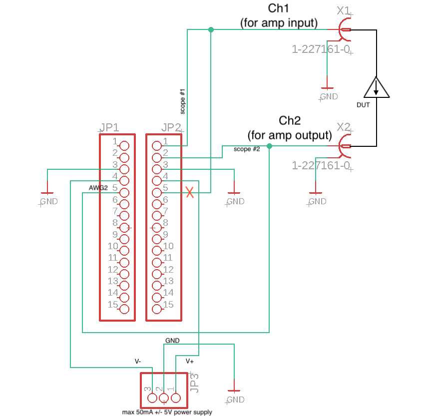
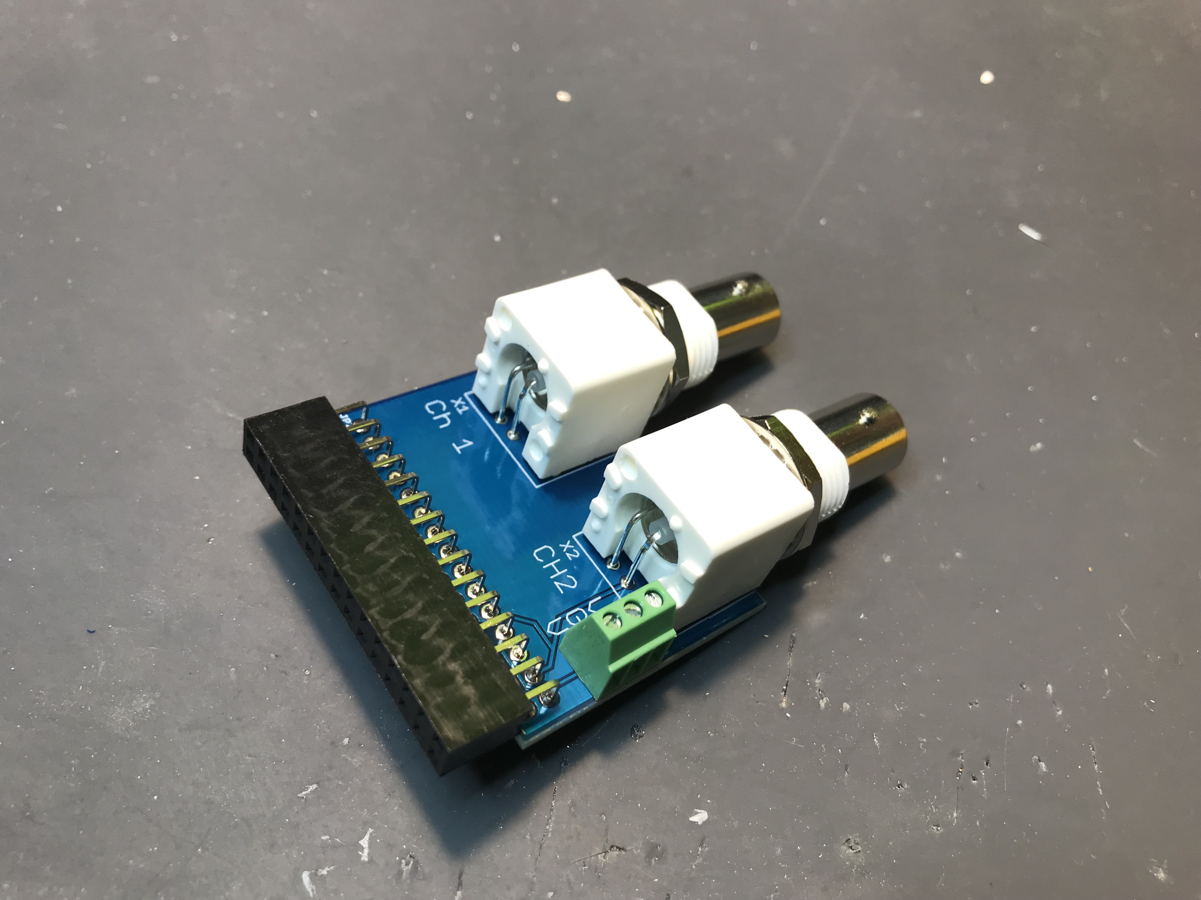
ADALM2000 by Analog Devices is quite multi-function device but I could not find "how-to" for my specific application. So I will show how!
 kodera2t
Become a Hackaday.io member
Already have an account? Log in.
Just one more thing
To make the experience fit your profile, pick a username and tell us what interests you.
Pick an awesome username
hackaday.io/
Your profile's URL: hackaday.io/username. Max 25 alphanumeric characters.
Pick a few interests
Projects that share your interests
People that share your interests

 Boolean90
 mit41301
 kamalkedin123
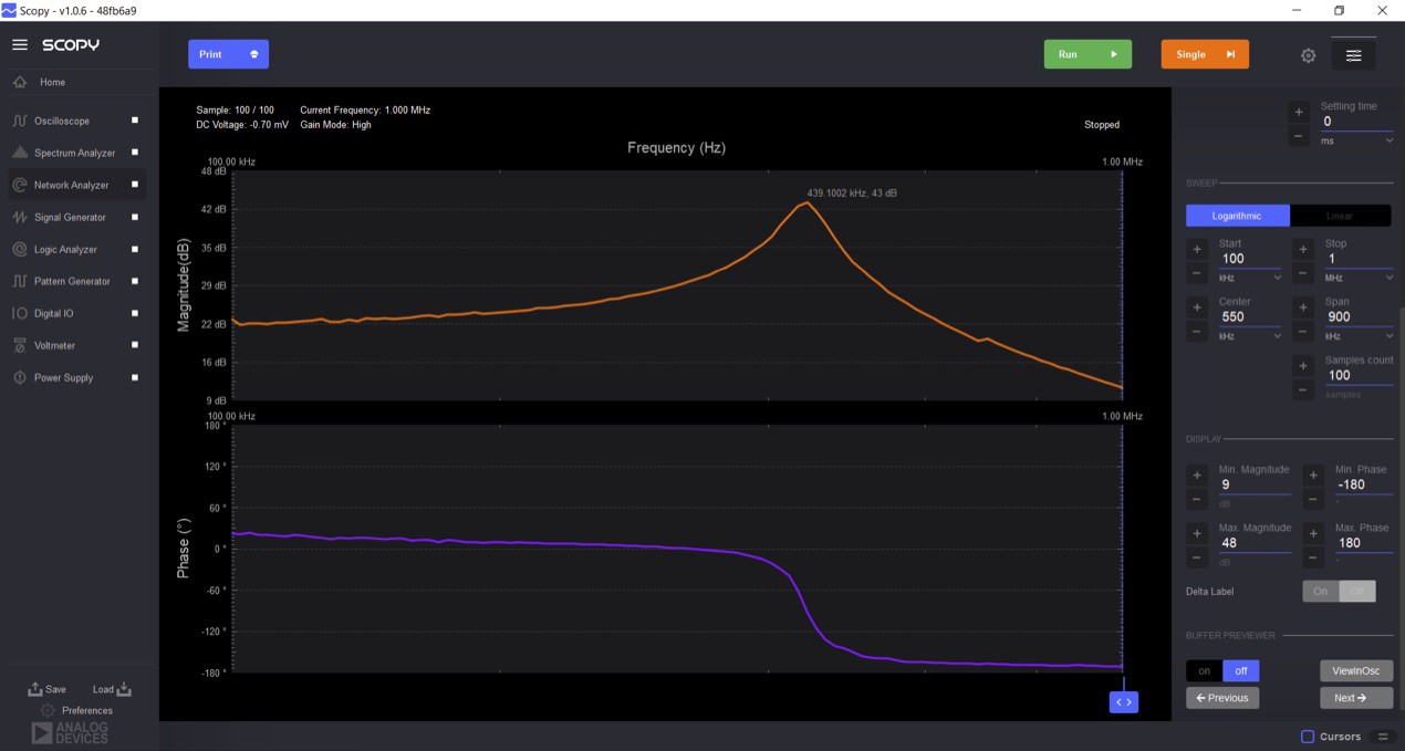
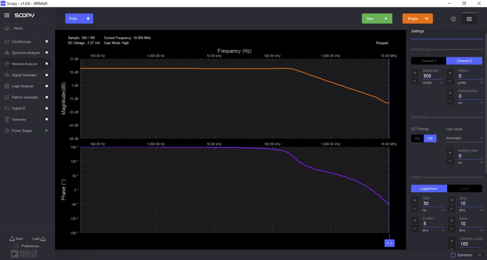
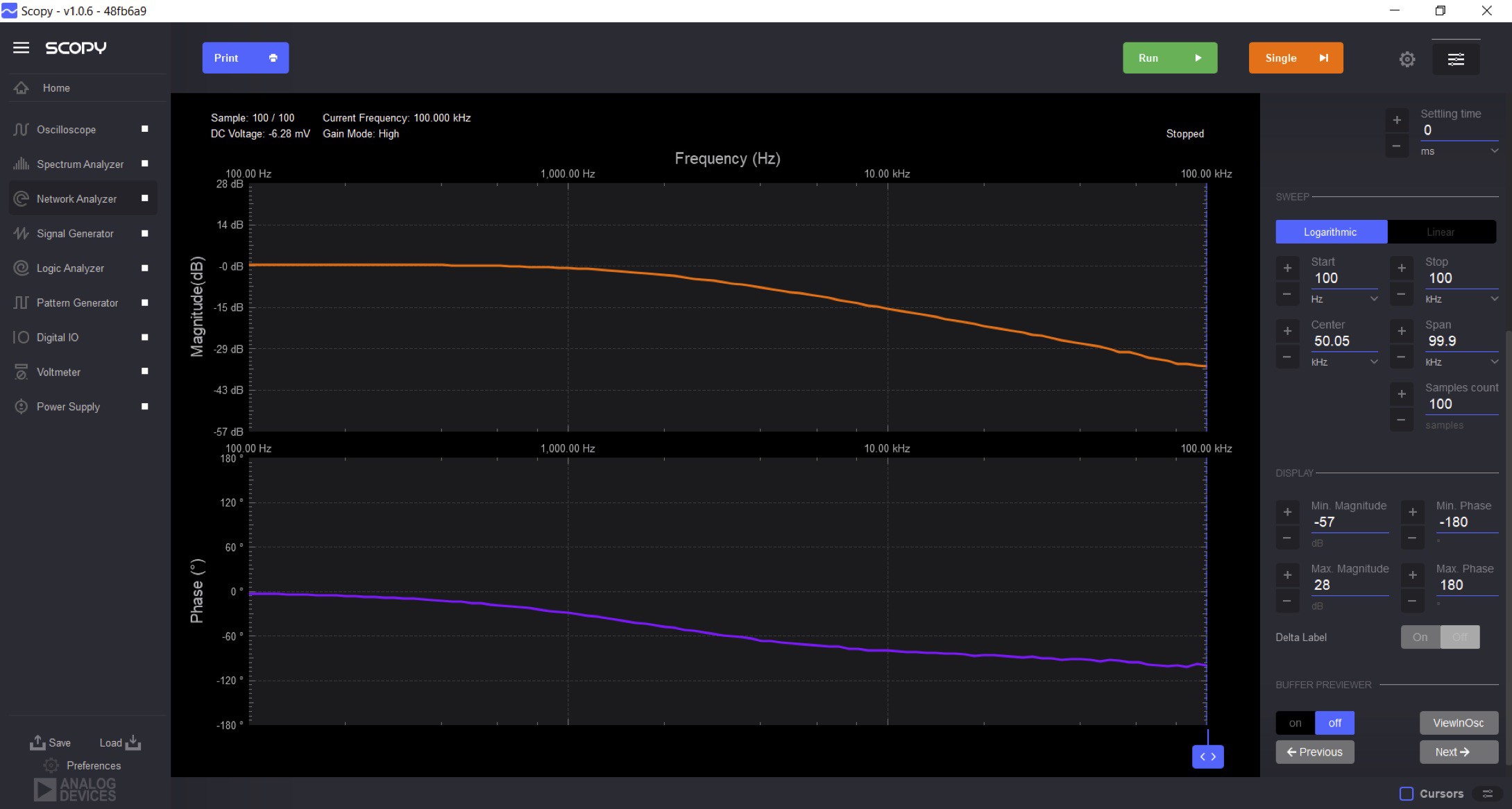
It would be very interesting if you try to measure the gain margin and phase of the control loop of a switched source, I am thinking of buying the adalm2000 but you scared me with the 40dB gain of the inductor, very good your adapter I think the analog discovery brings it.