Travel Configurations:
125-200mm
150-250mm
175-300mm
200-350mm
Specifications:
Designed around 0.125" (3.175mm) ball bearing
Screw Pitch Diameter: 12mm
Screw Pitch: 4.5mm
Actuation Speed: 23.1mm/s
Encoder: 62.66667P/mm
Gearmotor: No Load 560RPM, 0.5A (See attached observations)
Force: 105N @ 1.0A (assuming 75%e)
Force: 367N @ 2.4A (assuming 75%e)
I have not tested linear force simply because I don't have appropriate hardware to do so. At 1.5A, I am unable (or unwilling) to stop the actuator by hand in compression. Further testing will happen as I utilize the design.
Example of encoder/pid positioning: https://www.youtube.com/watch?v=KTAoLJEhHUw
Ball Screw:
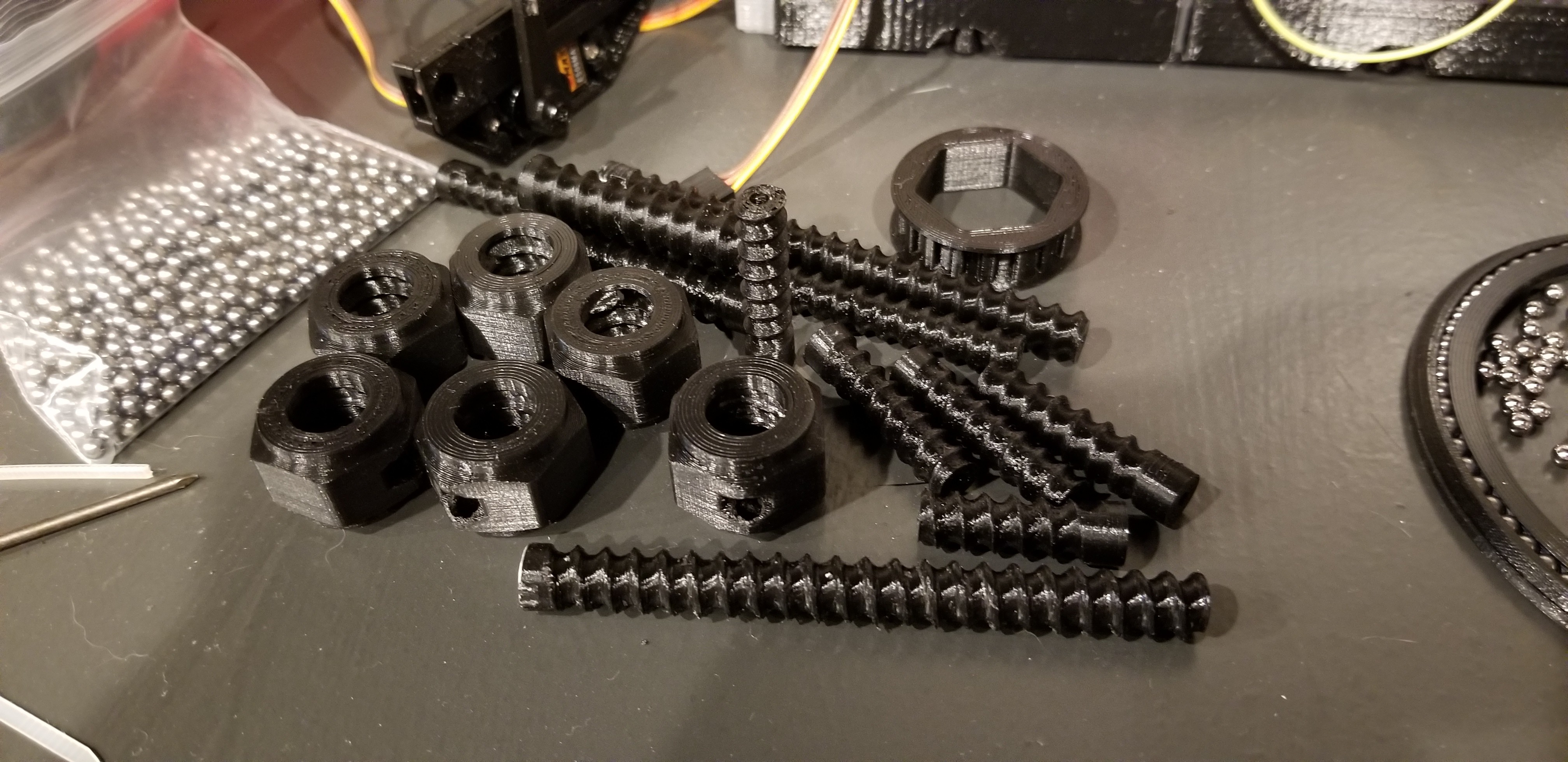
Designing the ball screw was largely trial and error to dial in fit tolerances. Many tests were printed to refine the fit.
Belt Drive:
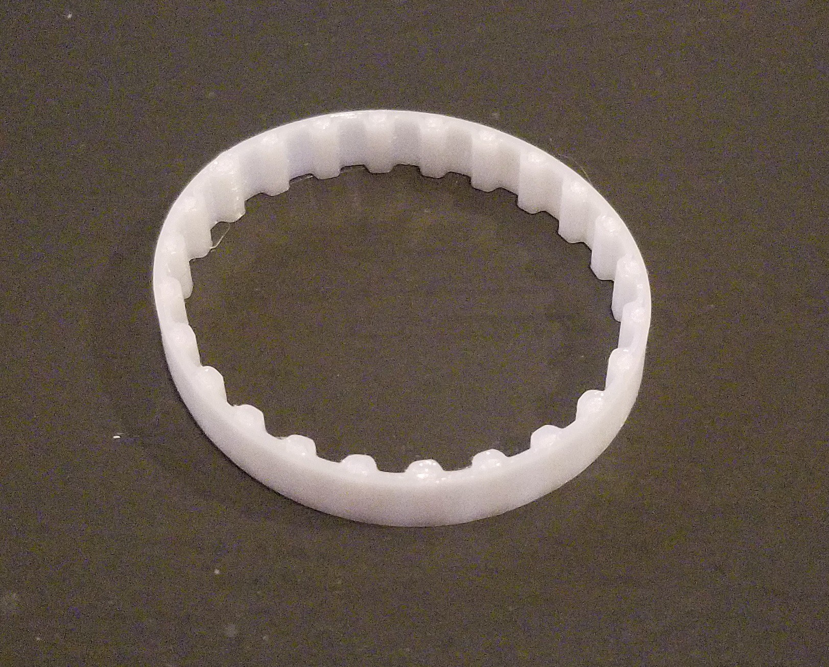
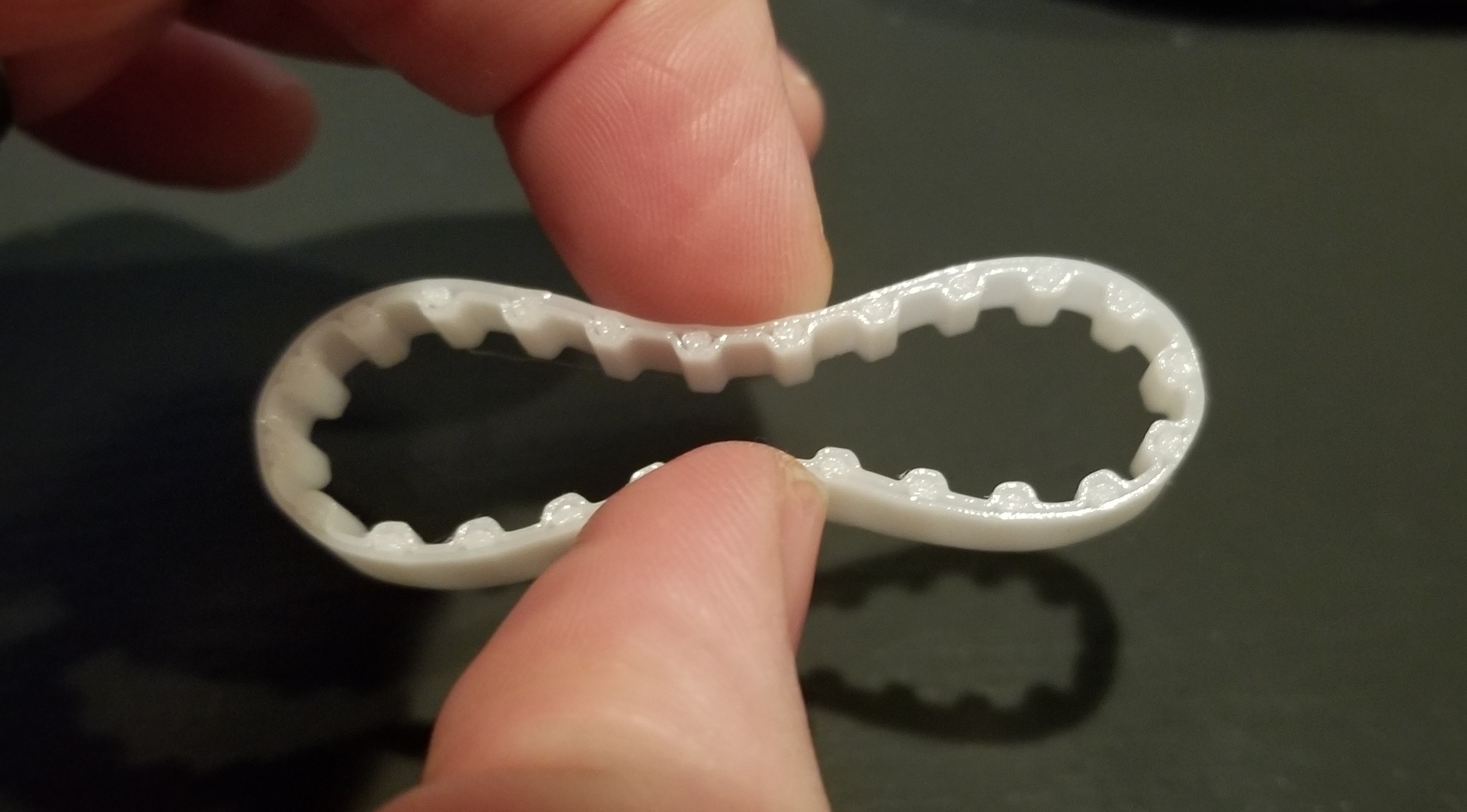
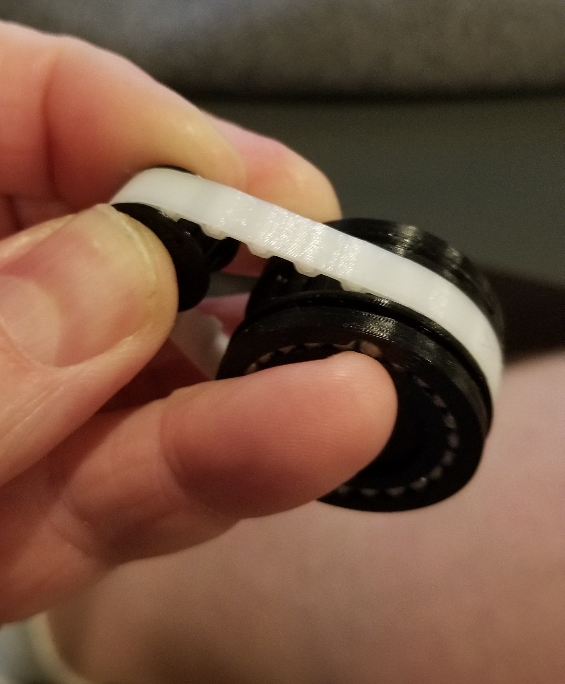
The option to buy T5 belts was considered but I decided to design T5 variants with a flex PLA which has worked out well past my expectations! Not only can I make hundreds of belts for the cost of one, my designs can be flexible with respect to pitch count and belt width to accommodate a wide range of applications.
3D Solutect FlexPLA has resulted with a very flexible yet mostly inelastic belt idea for transferring torque.
Gearmotors:
Starting with the motor, due to the high individual part cost, I purchased several different motors and gearmotors, with and without encoders to test torque/rpm capabilities. This determination was most important in determining the intermediate drive train and ball screw characteristics to achieve a 'decent' actuation speed. The goal of ~15-20mm/s was set.
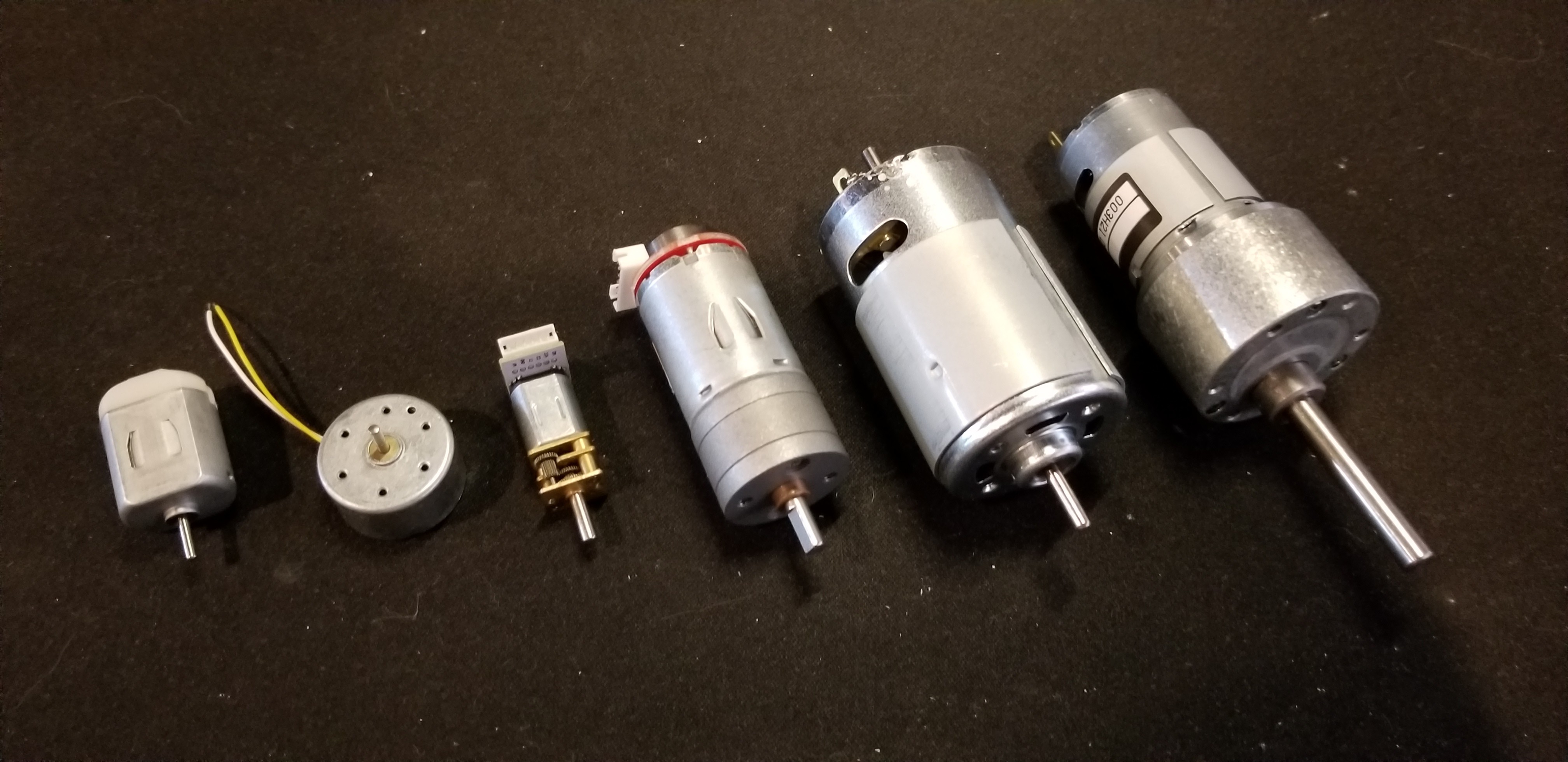
Dozens of motors later (some bulk orders from china)
Gearmotor Load Test:
Gearmotor 003H21-ORB was finally chosen and most thoroughly tested. The testing apparatus was crude but yielded repeatable observations. Utilizing 3D printed components, I was not able to stop this gearmotor even only at 4-5amp at maximum applied load. Recording several high speed runs I was able to plot gram mass, current, and RPM which plotted uniformly and linearly. See attached datasheet for gearmotor. Unfortunately the eBay reseller has very little information on this motor but at 9$ it is a steal.
Purchased from ebay: https://tinyurl.com/y5dbkexq
Mounted gearmotor to desk with 150mm torque arm and gram scale.
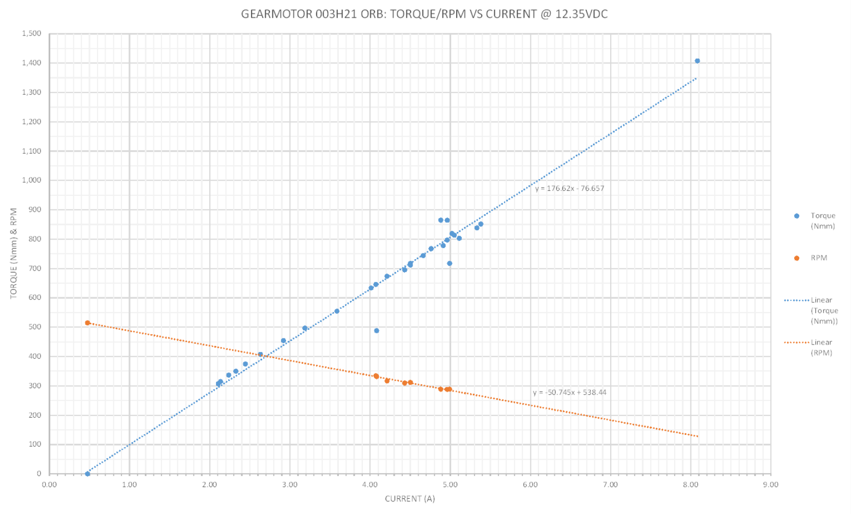
Gearmotor 003H21 ORB Observations
Controller Selection: DC Motor Driver
Testing several DC motor drivers I showed the TB6612FNG 2x1.2A DC motor driver module running both channels in parallel worked very well with the 003H21-ORB gearmotor. This DC drive gave fine motor control >1VDC when using a nominal 12VDC power supply.
Roboshop: https://tinyurl.com/y2vdwjyn
Controller Selection: Encoder
Some gearmotors tested had built in encoders, which was nice, but the selected gearmotor did not. Reviewing different options; magnet incremental encoders were too costly and hall effects would be more difficult to implement. I chose a very cheap, hopefully not too cheap, non-dedenting rotating encoder. The plastic shaft in the metal housing is not idea for longevity so the design best supports the encoder gear to minimize any side loading.
Digikey: https://tinyurl.com/y265l4ul
My original goal was to use (1) Atmega168 to control (2) ball screw assemblies. The limiting factor will be the single microcontroller's ability to read both encoders utilizing one interrupt pin each. I still need to do position repeatability tests to confirm if this is possible. Buying enough for one board per actuator would solve this and at 1.29$ each, I did. I also have a stack of STM32s if needed. Since the DC motor driver is now one per, I was toying with the idea of integrating the controller and driver on the actuator frame itself to simplify connectivity, but that will be later.
For communication among on the child microcontrollers I was excited to implement...
Read more »
 Paul Gould
 yowhwui
 John Taylor
 Saul
Saul
That was the exact same assumption i made a while back. as mentioned the main benefit i got from switching from steel to acetal was wear reduction. 0.2 mm is good! if an application needed better tolerances someone could always just compensate for the backlash in software. Are you able to back drive the screw by hand?
Unsolicited Suggestion Section------(your welcome to ignore)-----
Acetal also works much better with rigid printed plactics, ie acrylic, pla, peek, pc, ect. If you need a really good fit for longer periods of time, lapping compound plus printing slightly smaller seems to work well for me.
NOTE: these suggestions are based off anecdotal evidence, with radial, angular contact, and slew ball bearing ive printed in the past.