 Miroslav Zuzelka
First of all, we need hardware which will interact with firmware of the printer. Since we like and heavily use ESP32, the choice was easy. Basically we need UART communication with printer electronics, some status LEDs and UART to RFID reader. We wanted this to be as simple as possible, so we will use LCD on printer for status messages. Also we want this to be affordable as much as possible, we looked online and found this RFID reader at Aliexpress.
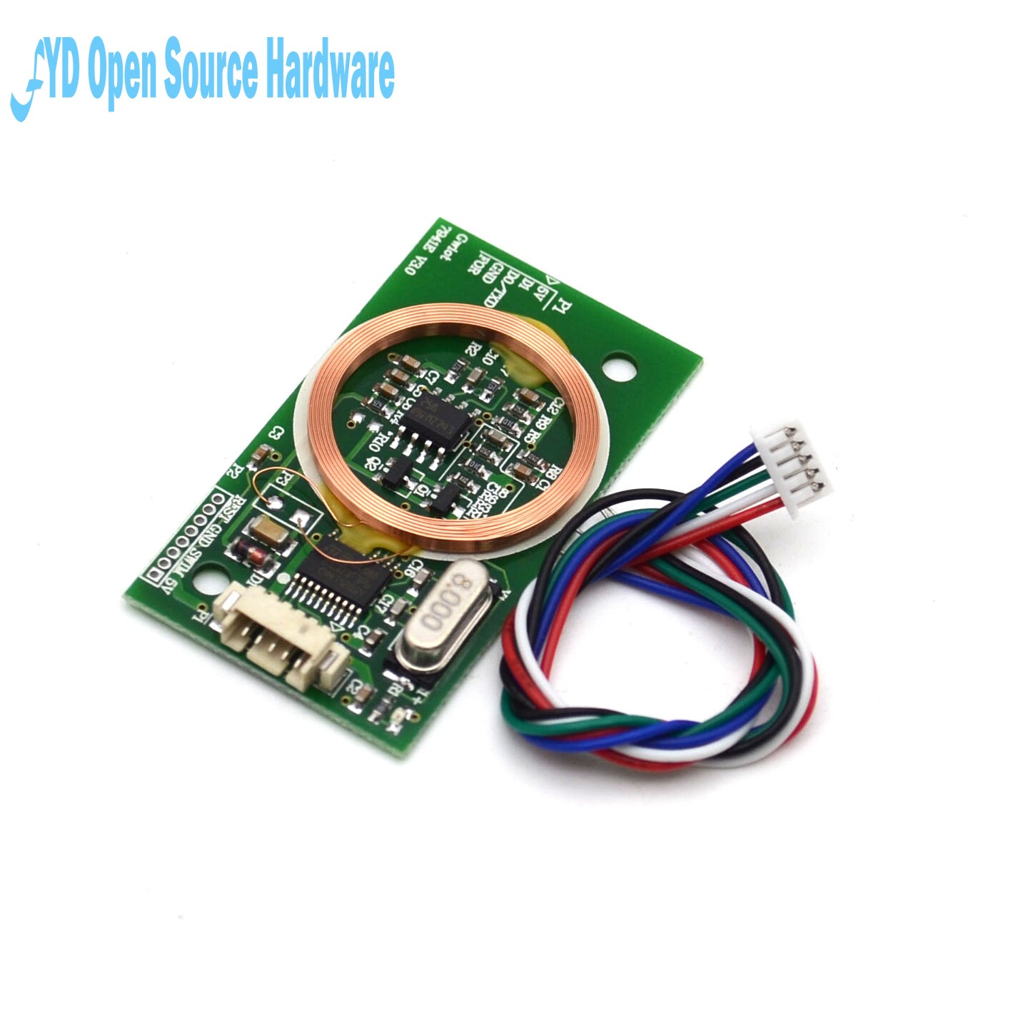
This reader just reads the card and transmits ID of the card to UART port.
Because we think that best place to have this reader would be in LCD cover, our member (Jan Chromec) redesigned LCD cover to accommodate RFID reader & ESP32. These will sit at side of the LCD and can be powered from printer. I designed first PCB and to be sure that everything lines up together, I made prototype from cardboard on laser cutter. I glued connectors to their place to ensure that they will fit in hole and will not collide with anything. You can see how it looks like on next picture. This is just one prototype of the PCB, with spacer and RFID reader in place.
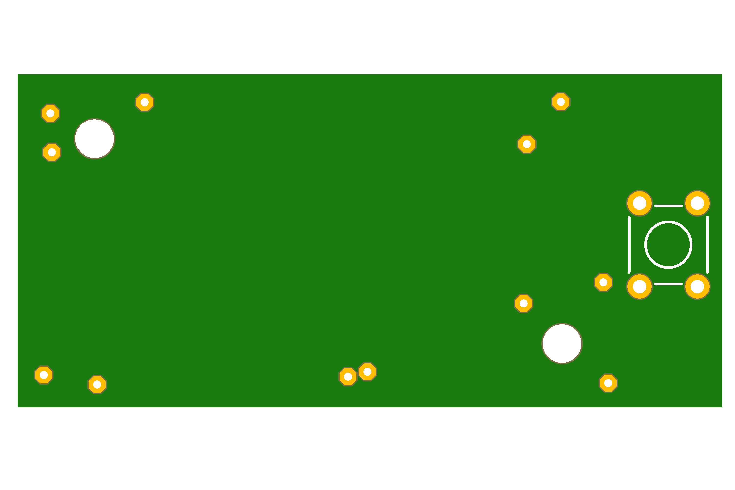
Here is revision A of the board:
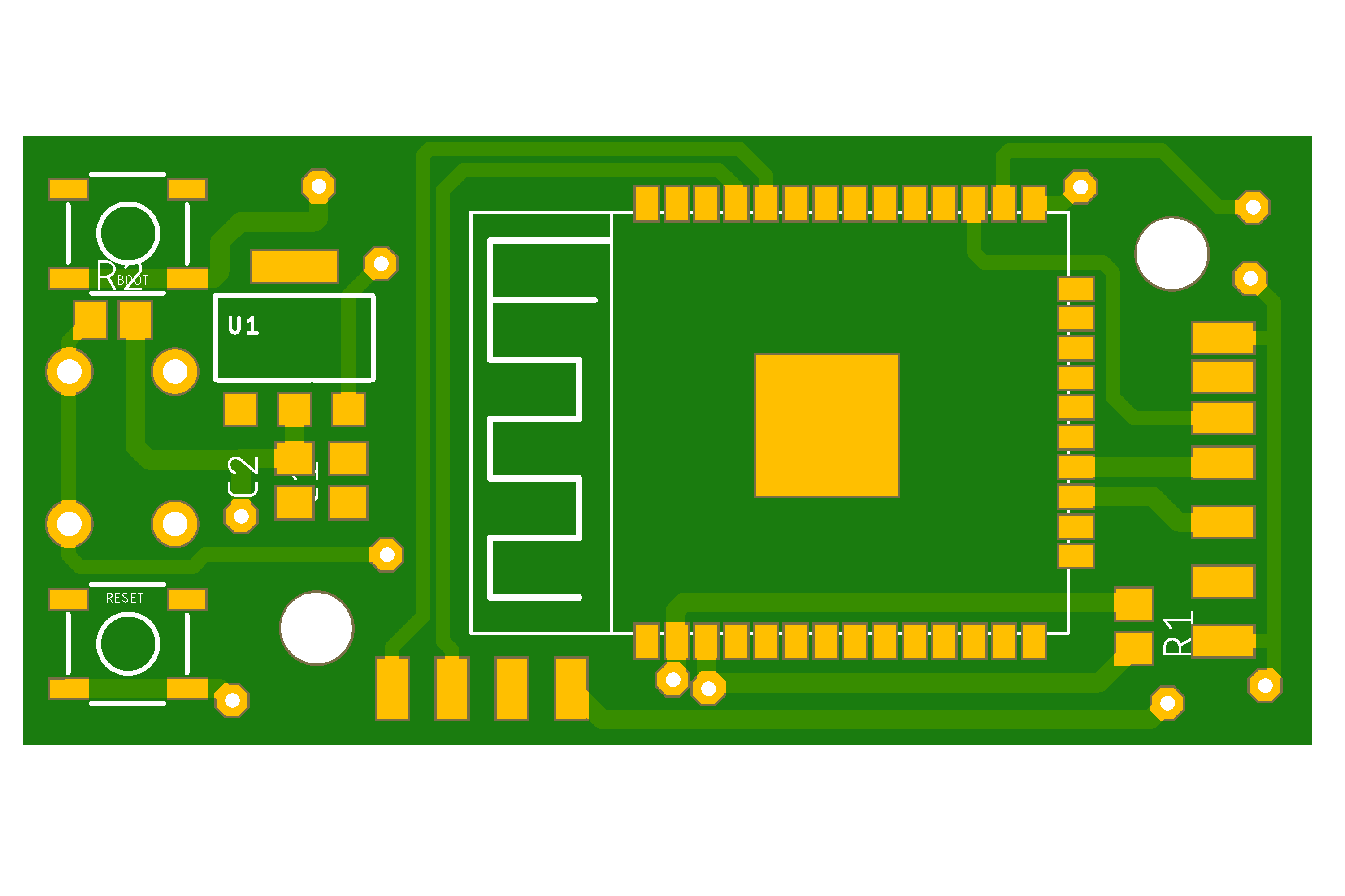
Revision A did not make it to the PCB factory and I redesigned whole board to revision B quite early I finished it. Here is revision B :
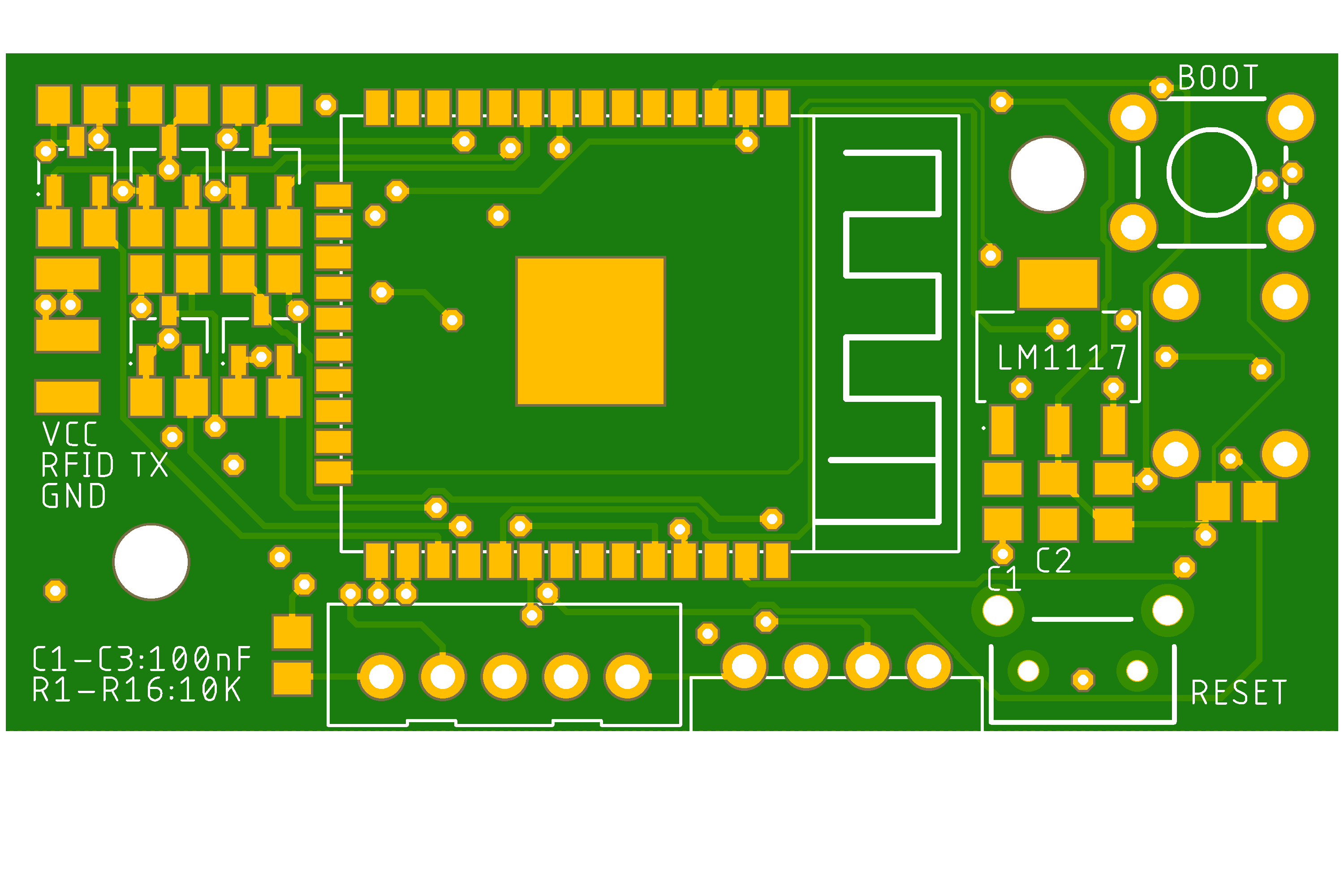
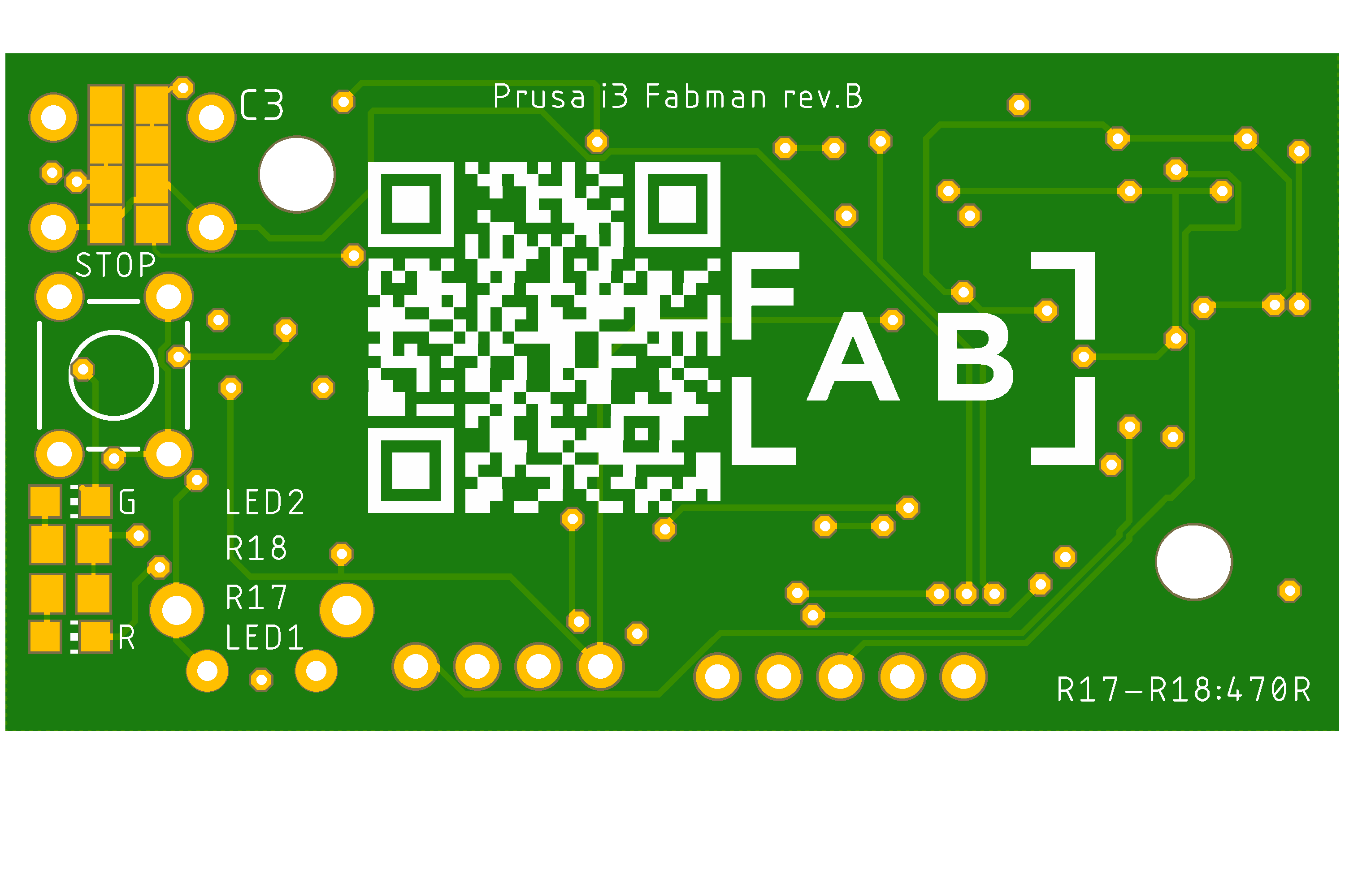
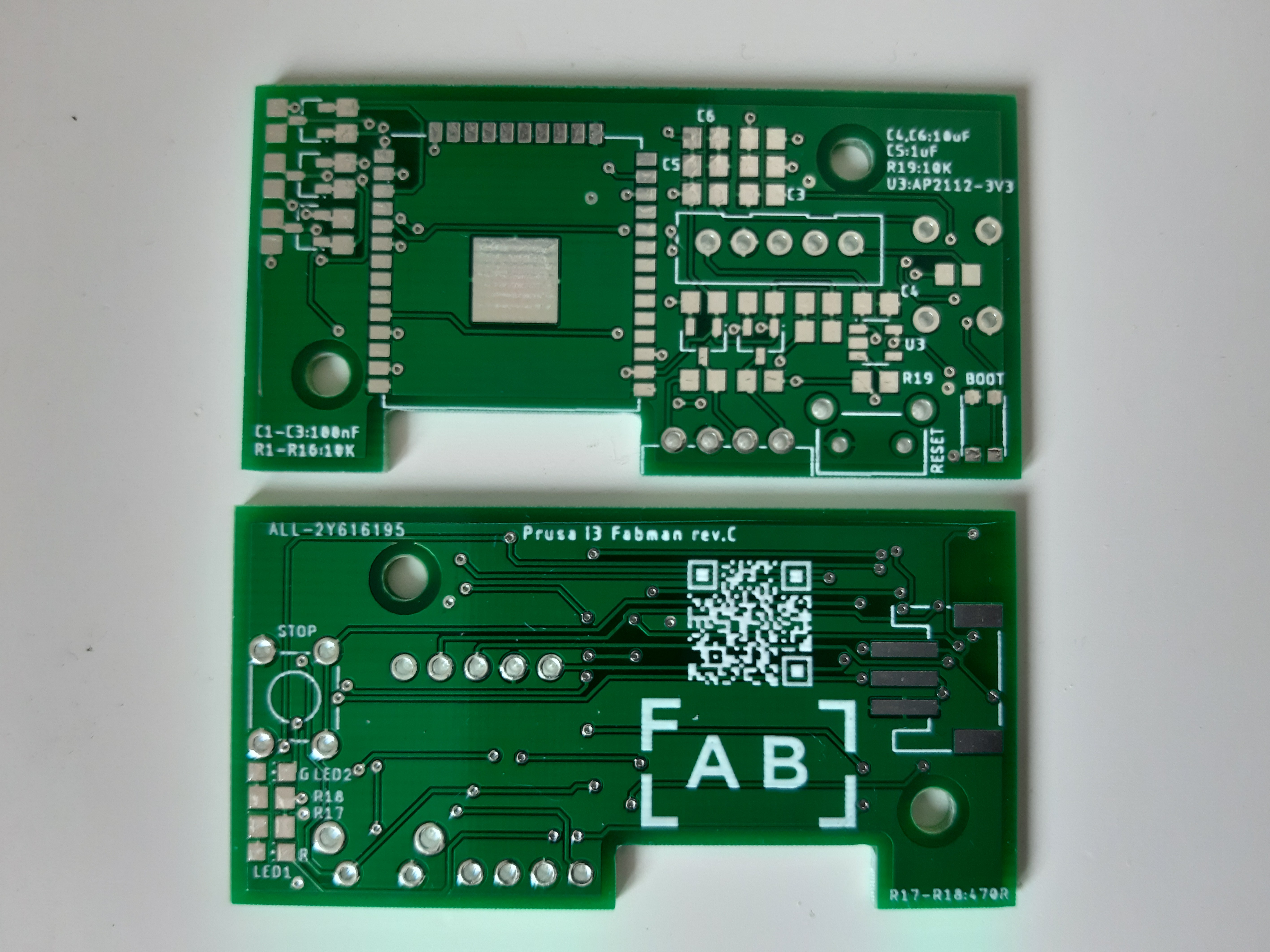
I designed this board so it can be hand soldered and does not need reflow oven, but it can be baked in it as well. Because of limited space and requirement of low price I did not include UART to USB interface and instead of that, board is programmed by external UART to USB converter. For there is on board Boot button with Reset button. 4-pin header is for external UART converter, 5-pin header is for power and UART communication with printer, RFID TX is for data line from RFID reader, Stop button is for sending end of the user session to server. Rest of the parts are just resistor & capacitors for power and voltage level shifters from 5V to 3V3. Red LED is signalization that board is powered and Green LED is showing information if we are connected to WiFi .
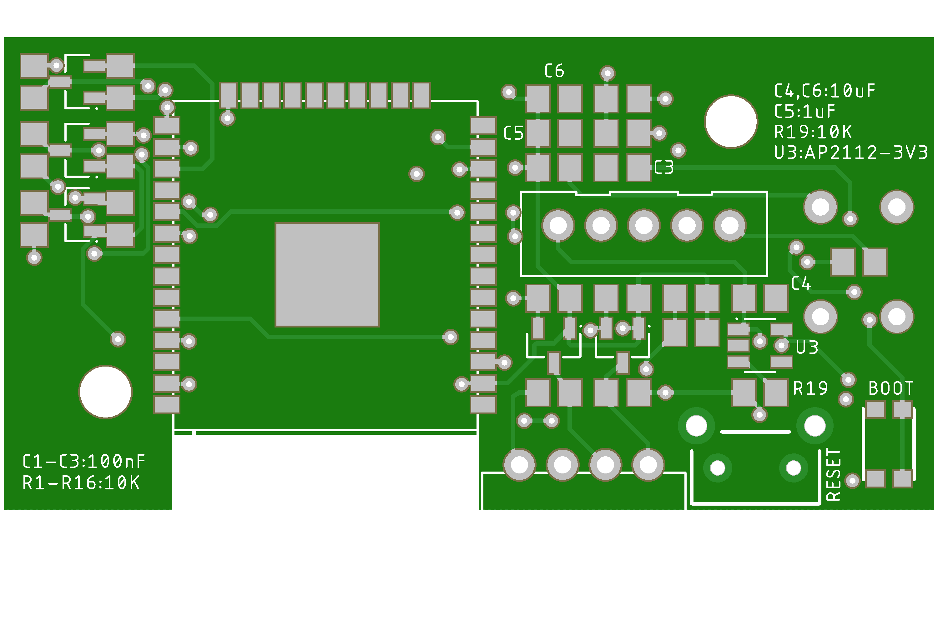
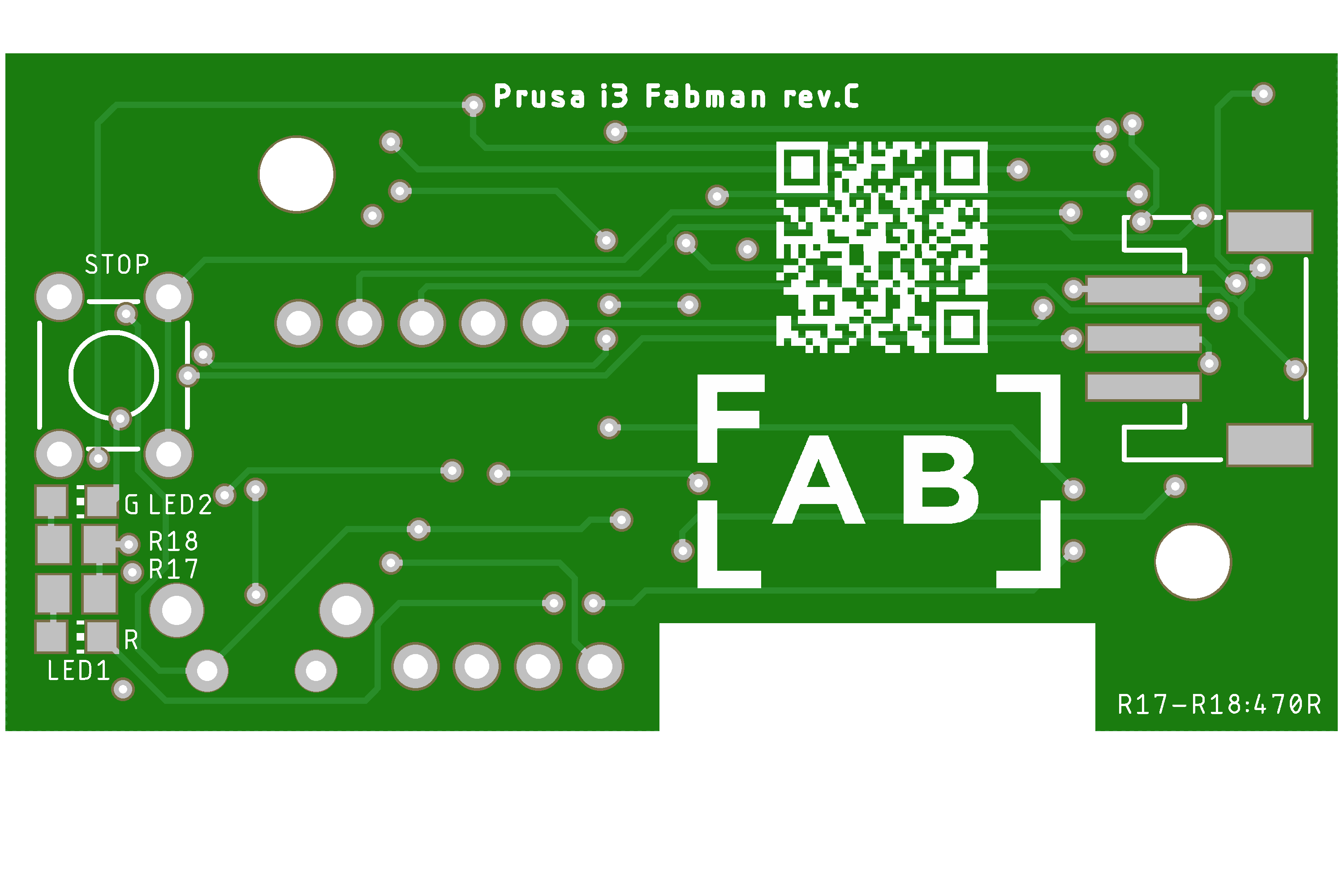
This board served as main horse for development of the firmware. Through development I did find out that I made mistake with pins for UART (printer side) and I had to cut the traces (or not to populate some parts) to make it work. Not long time ago I made revision C, where I repaired my mistakes and also changed composition of the parts to follow recommendation for placing ESP32 modules.
Most recent board look like this:
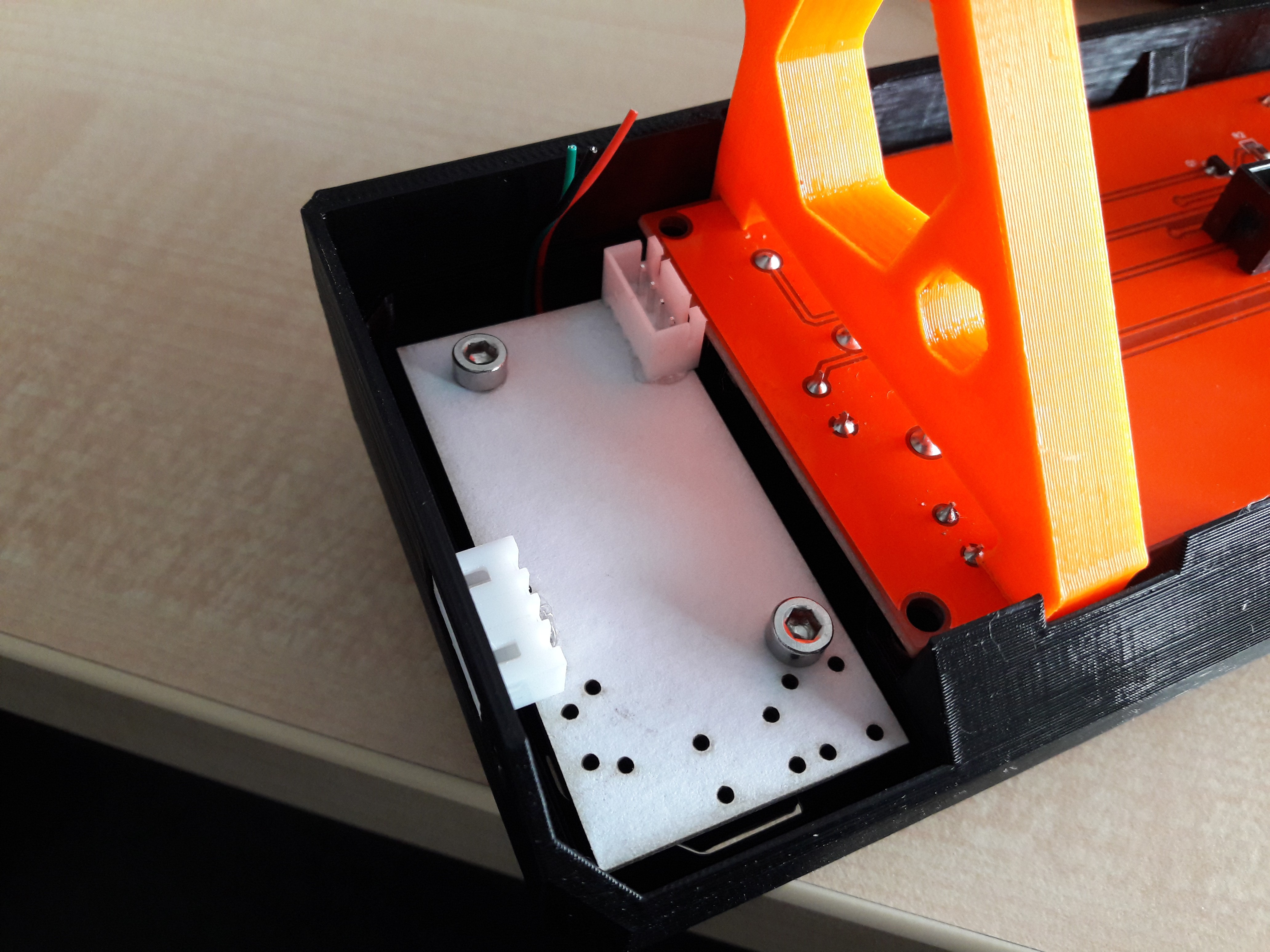
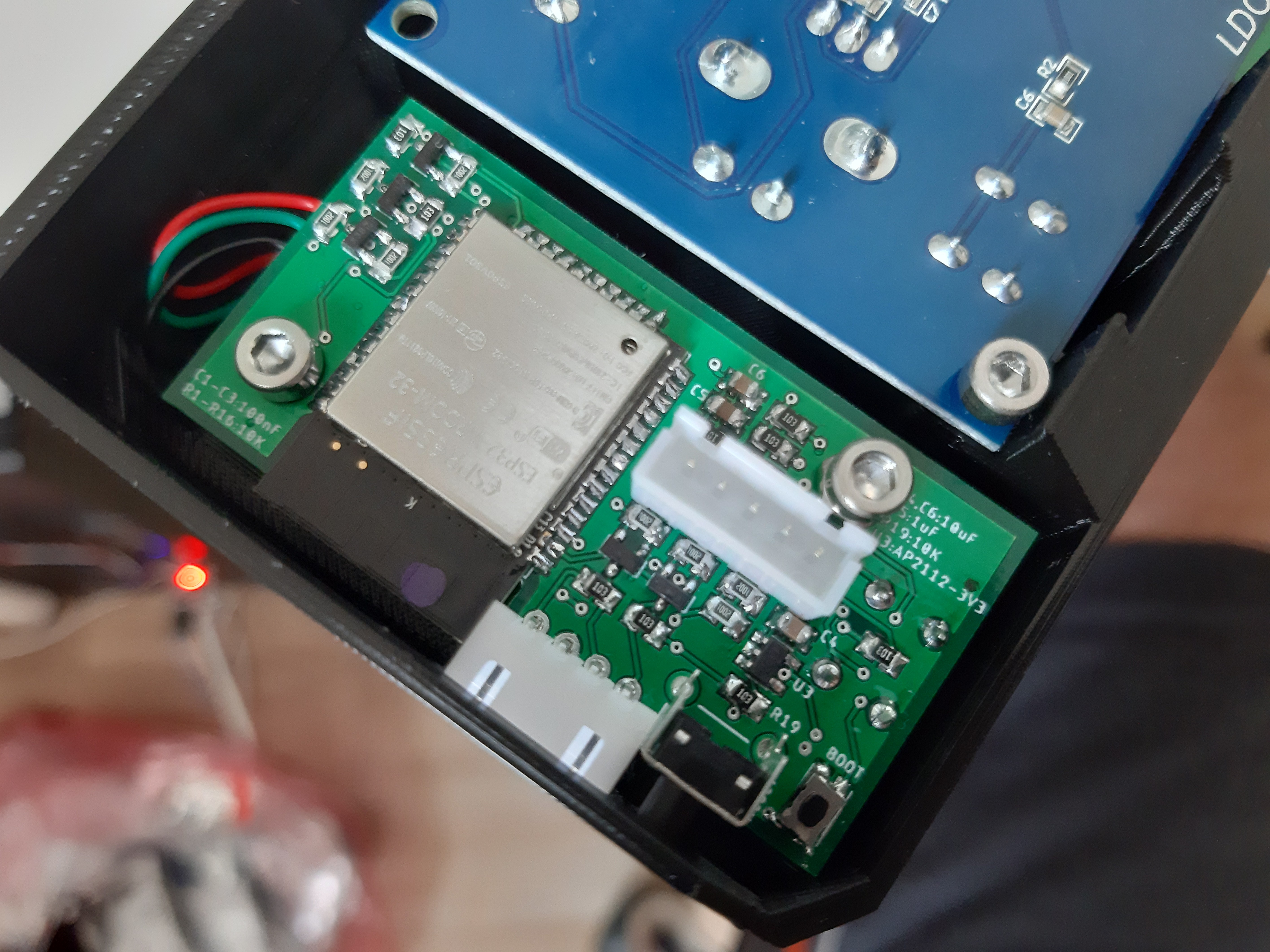
Here is already made board placed in our custom LCD cover:
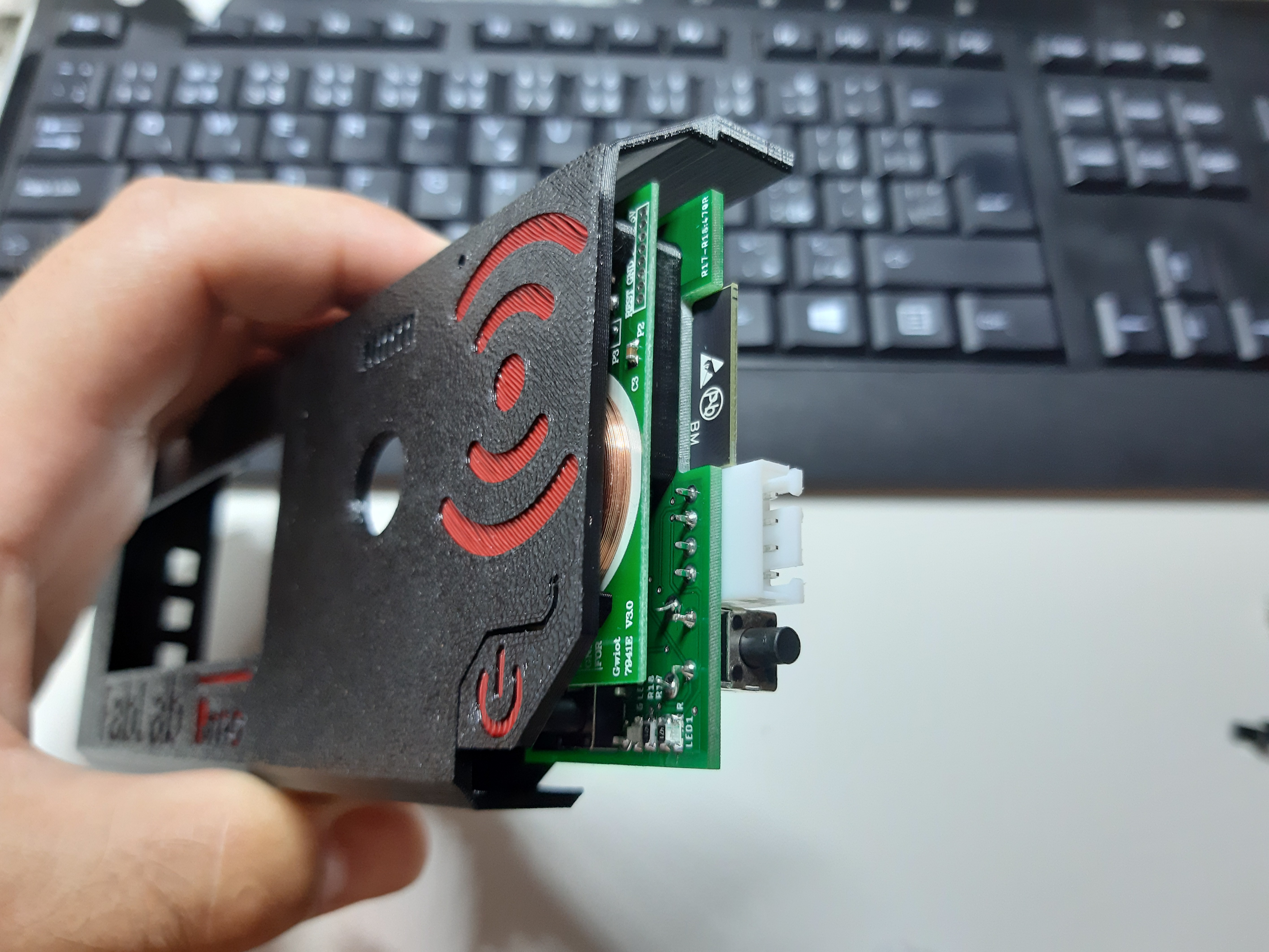
Here is sandwich (RFID reader -> spacer -> ESP32 board) in LCD cover which is just for showcase.
We had no problem with this board so far and we are using it on 10 printers right now (mostly revision B).
Hardware is done, now it's up to the software :) .
If you are interested in HW, or you want to just look, here is link for design files.
Discussions
Become a Hackaday.io Member
Create an account to leave a comment. Already have an account? Log In.