 Electroniclovers123
Here is the step description.
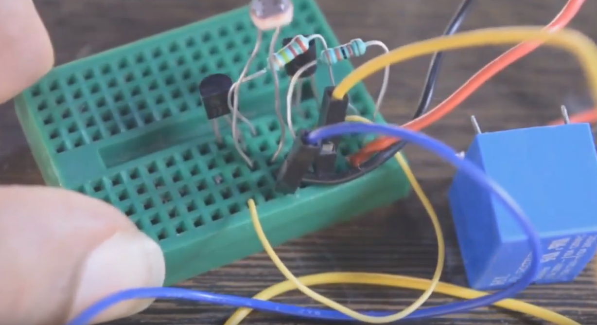
Step 1 :- Connect everything according to following schematic.
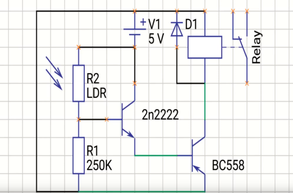
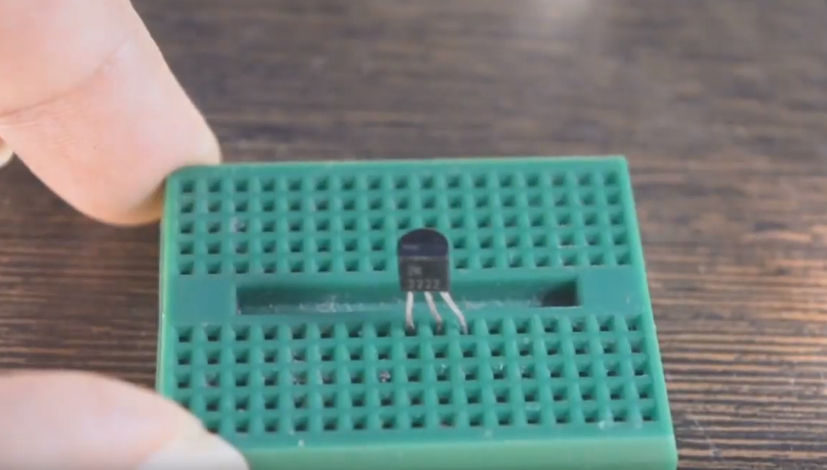
Step 2 :-Add NPN 2N2222 transistor to breadboard
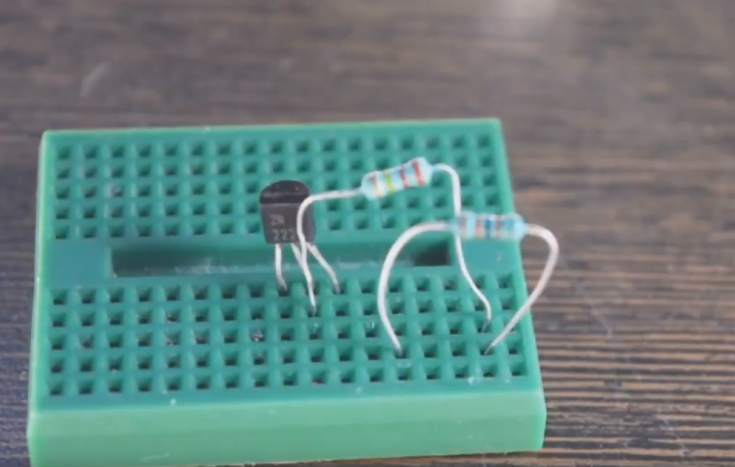
Step 3 :-Add a 250K resistor from the base of 2N2222 to the positive rail.
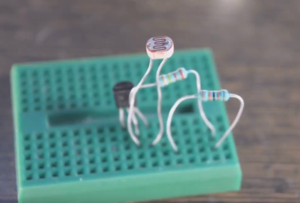
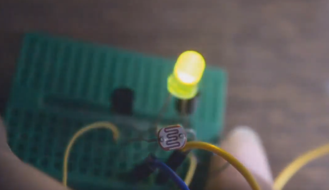
Step 4 :-Connect LDR (Light dependent resistor) from base of 2N2222 to negative rail.
Step 5 :-Add BC558 with its collector on Positive rail
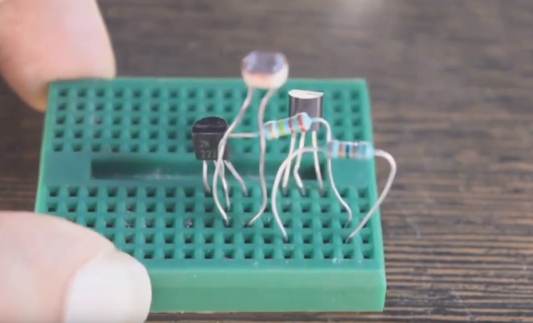
Step 6 :-Connect base of BC558 to emitter of 2N2222
Note:
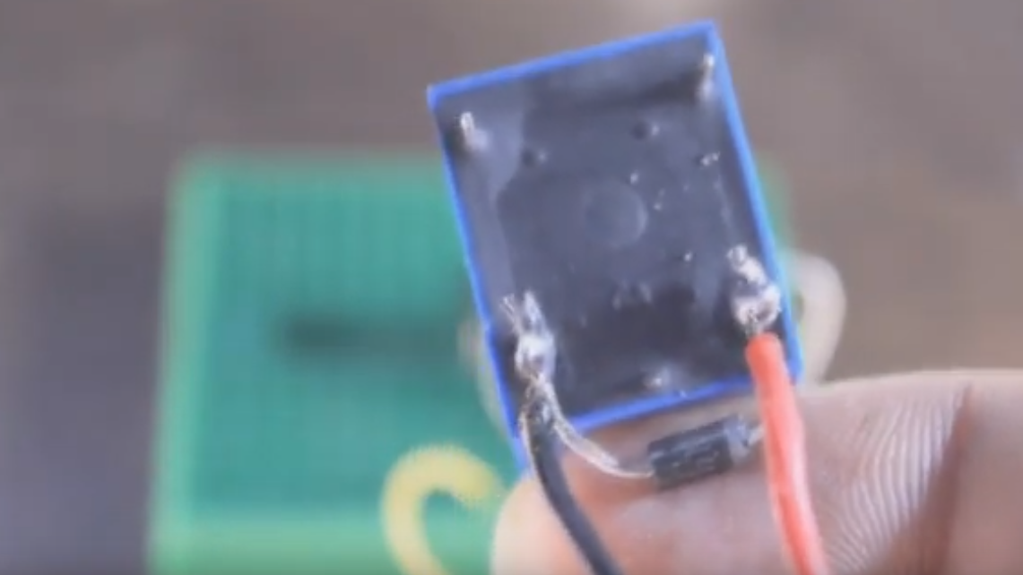
If you’re connecting an inductive load, like a relay or a motor, you must connect a diode in reverse bias configration to protect the transistor from back EMF but, if you are just using LED, diode isn’t needed.
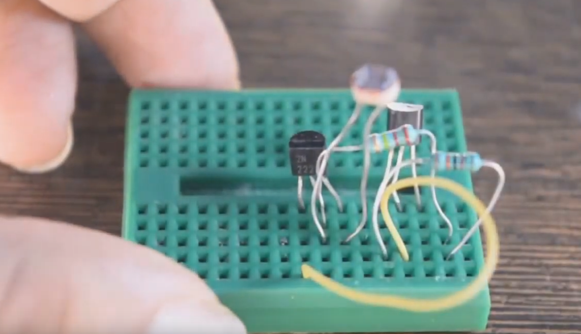
Step 7 :-Connect the load
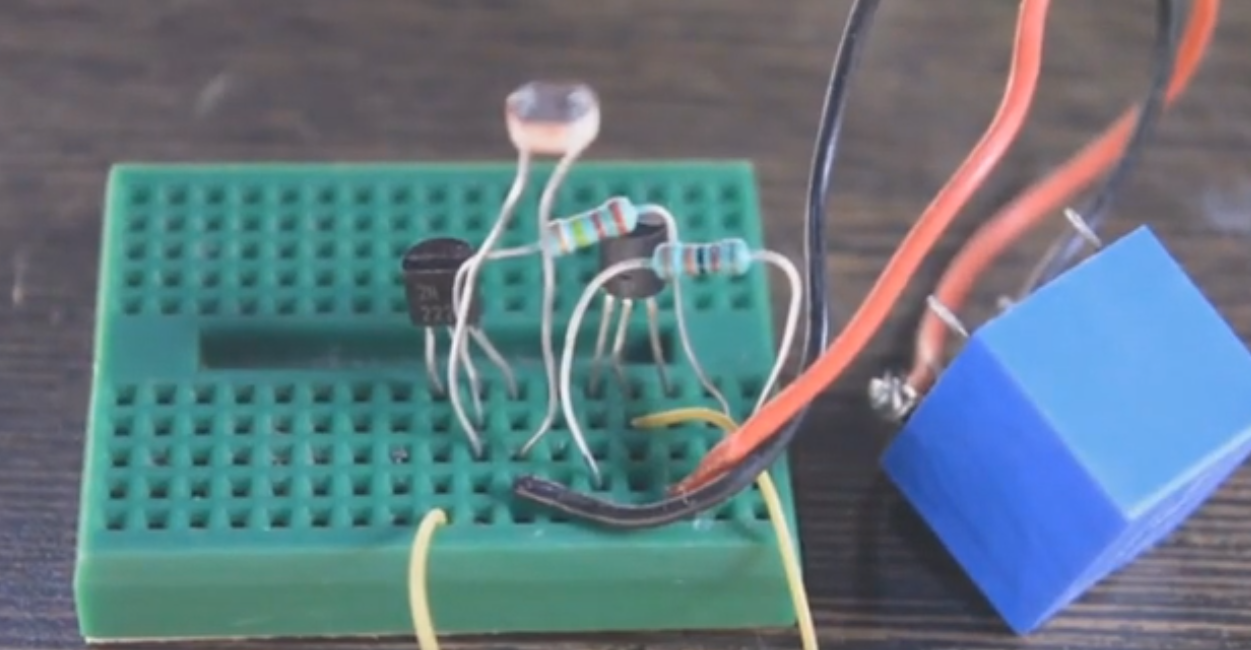
Step 8 :-Connect power 5V
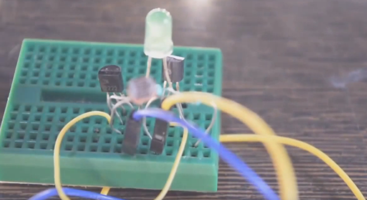
Step 9 :-Add LED instead of relay.
Products list:
『 2N2222 』 view more: https://www.utsource.net/sch/2N2222
『 BC558』 view more: https://www.utsource.net/sch/BC558
『 220K Resistor』 view more: https://www.utsource.net/sch/220K%20Resistor
『 5V Relay』 view more: https://www.utsource.net/sch/5V%20Relay
『1N4001 Diode』 view more: https://www.utsource.net/sch/1N4001%20Diode


That schematic doesn't look right to me. 🤔