 sporkius
Here is the Open Source Mill, Laser Lathe (Flower Router). It is the first open source closed loop servo mill.
Hardware:
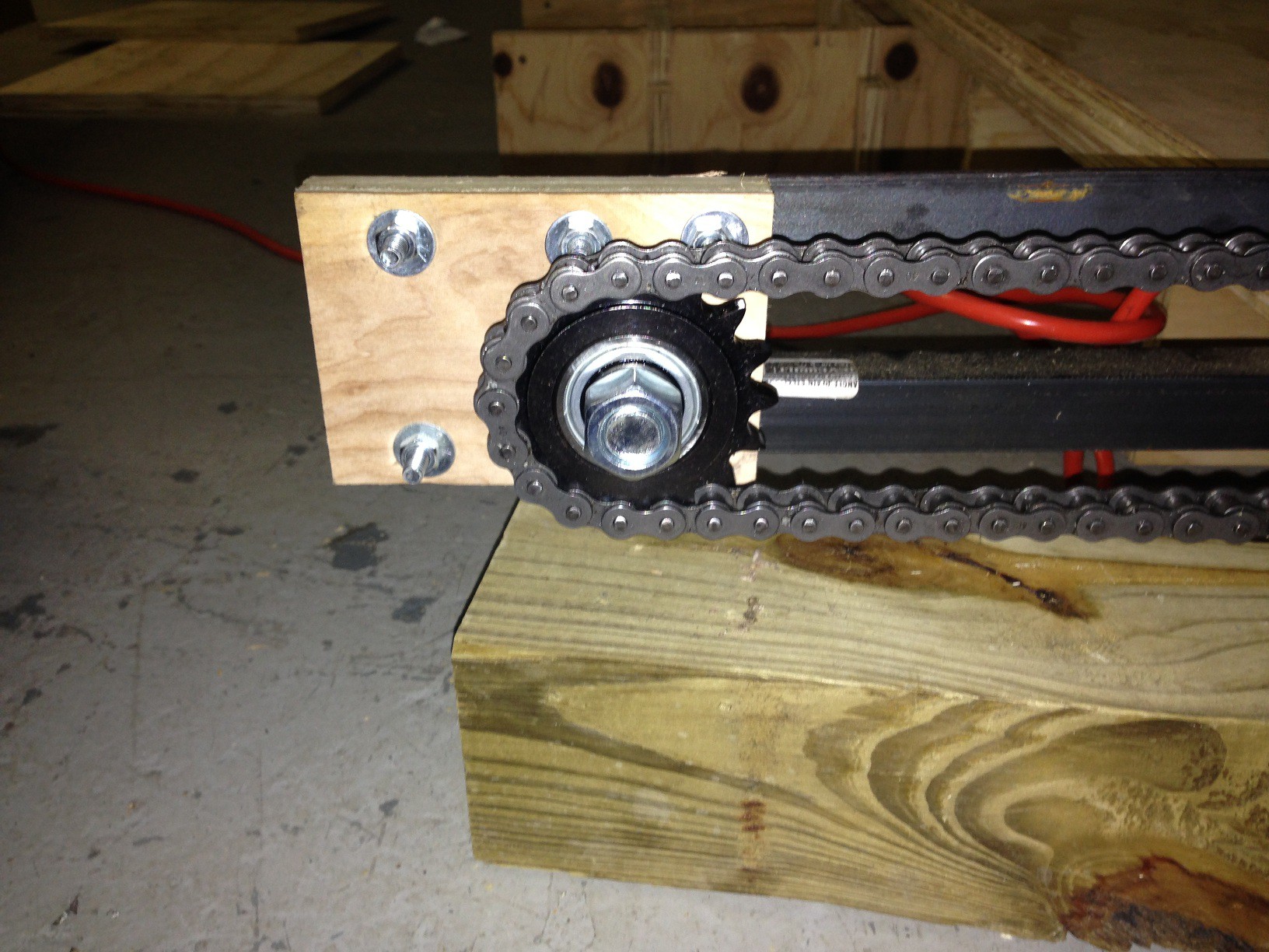
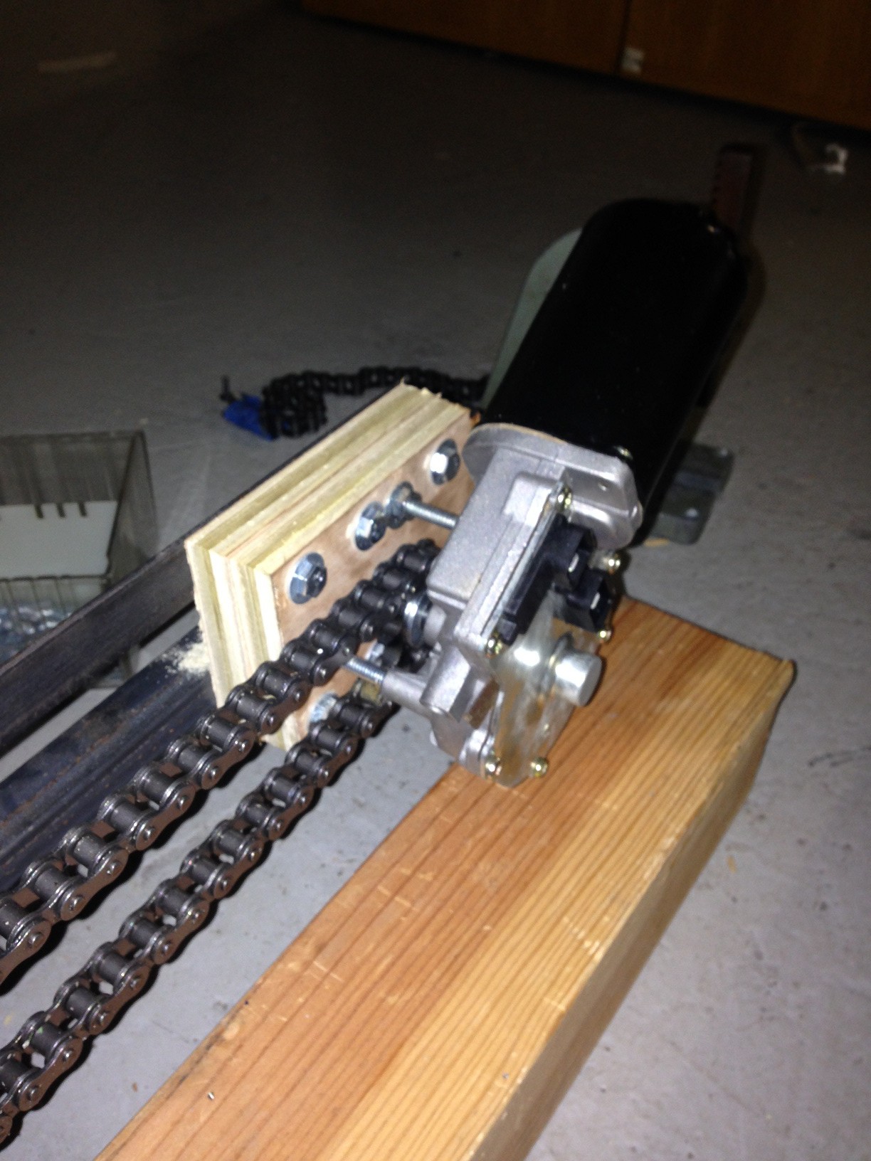
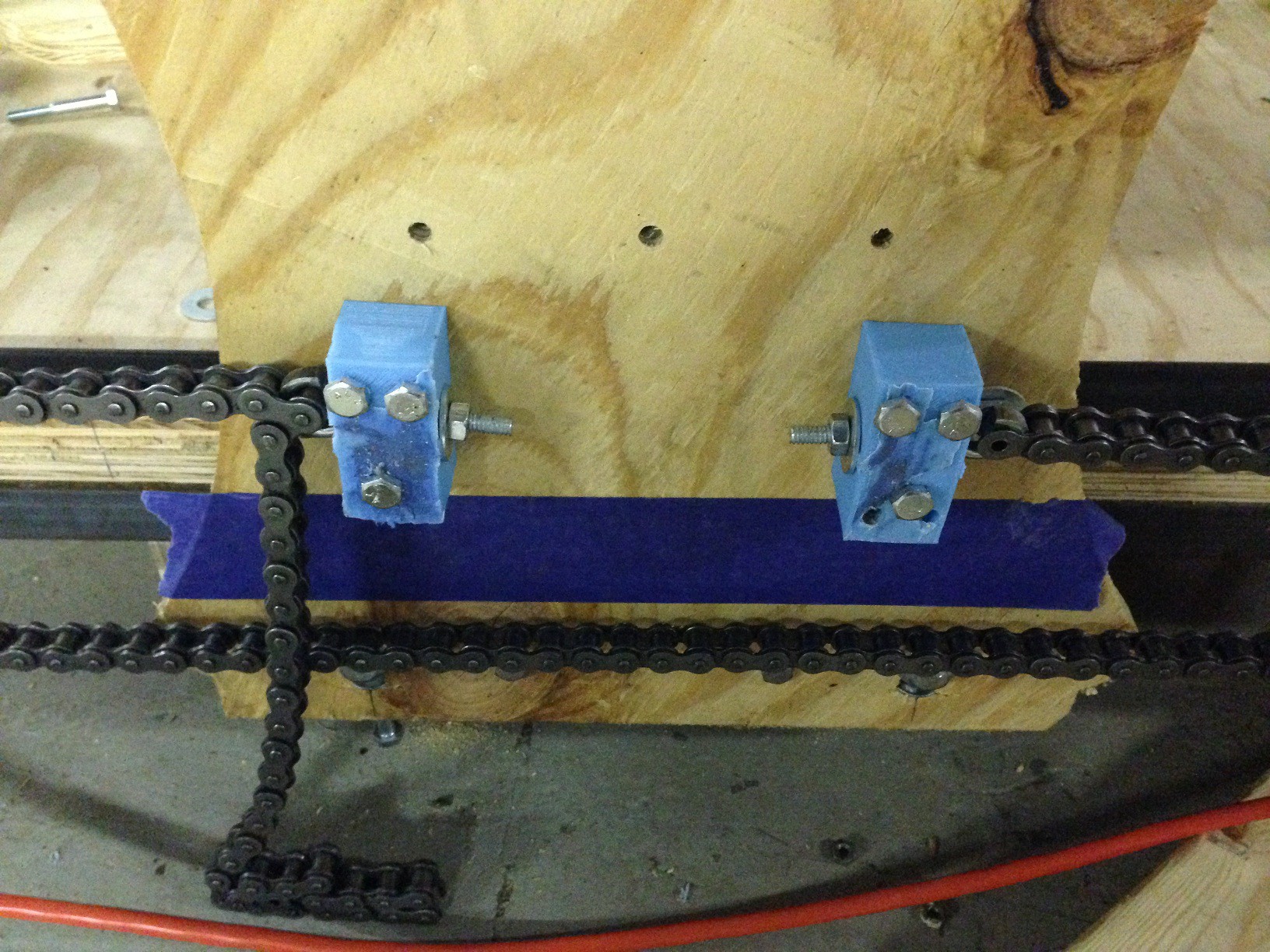
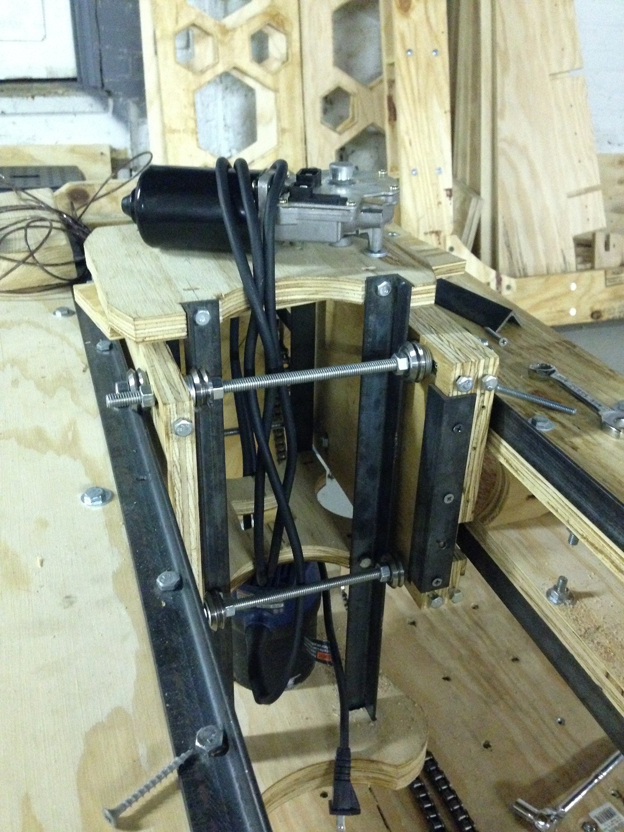
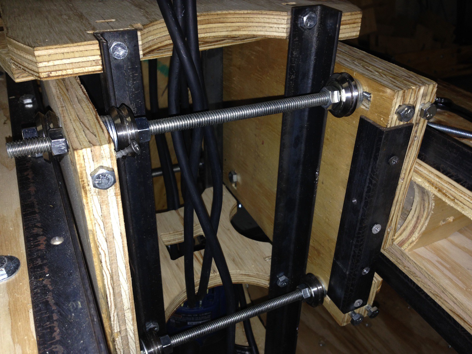
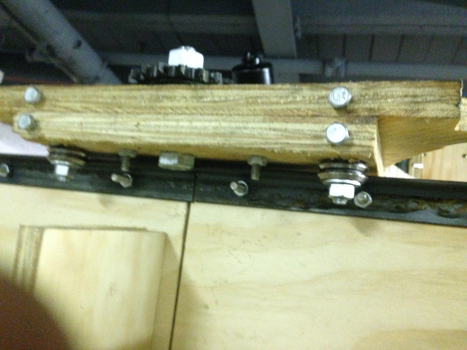
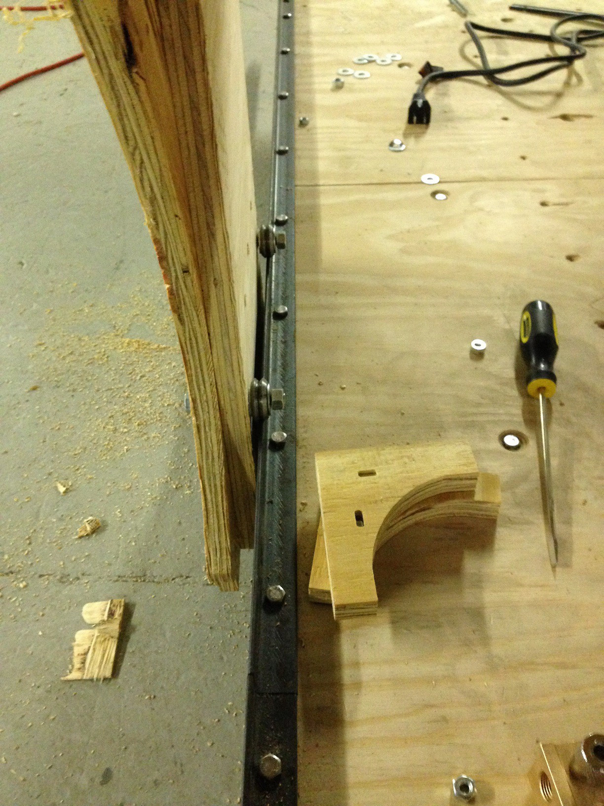
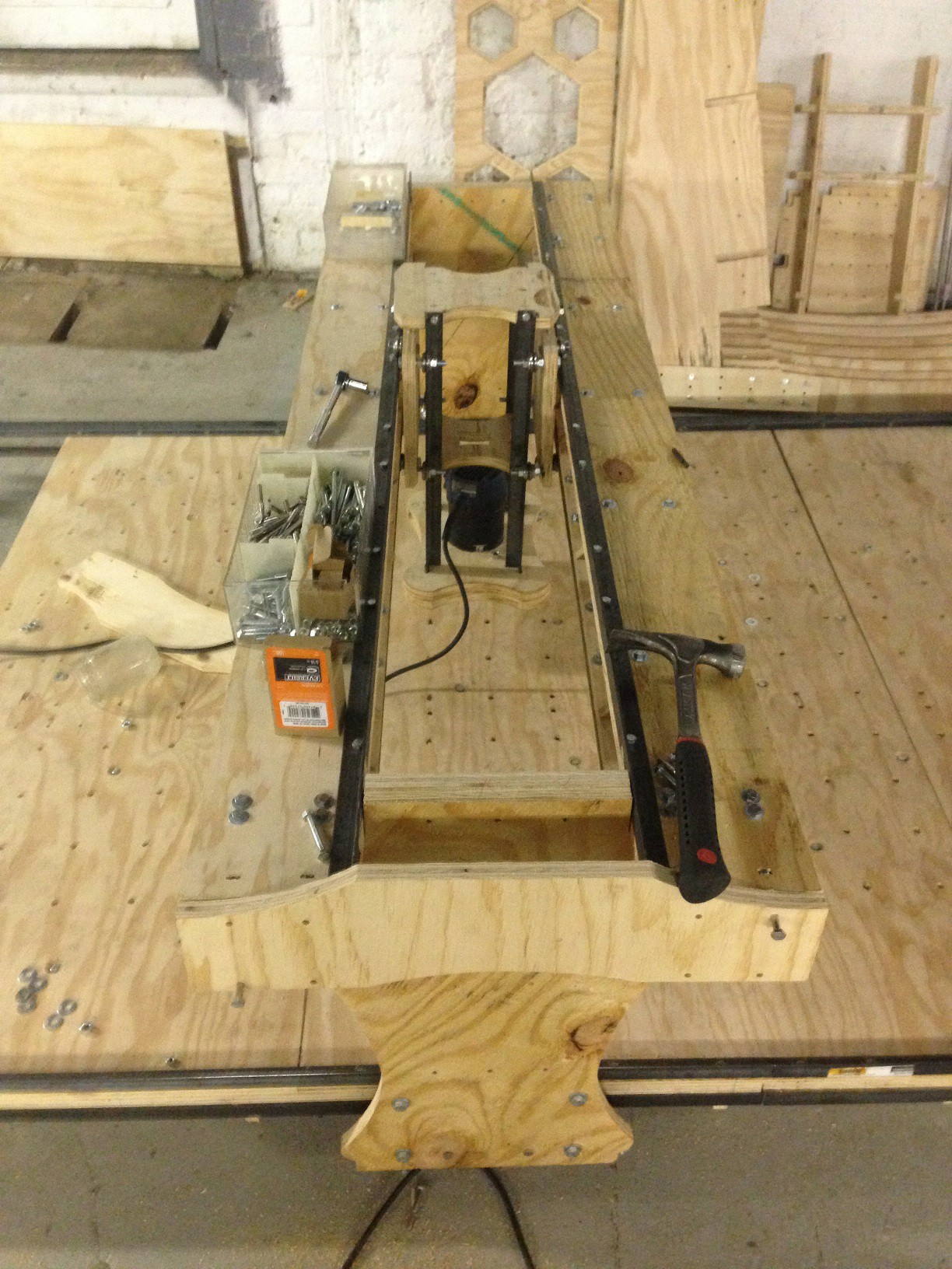
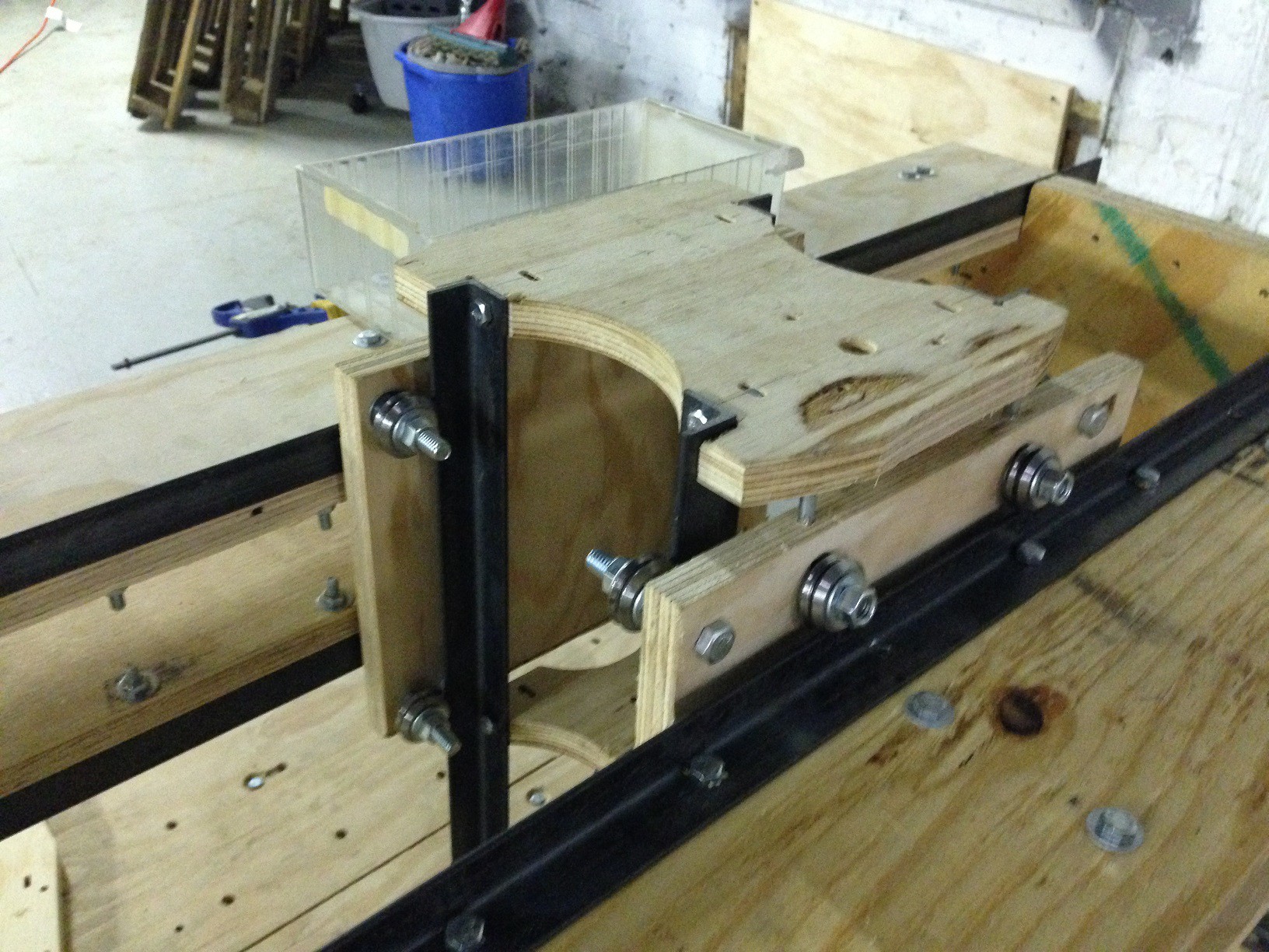
The entire machine is moved by Windshield wiper motors with a close-loop encoder feedback. #40 bicycle chain, sprockets and idlers are used instead of leadscrews on the x y and 4th axis. A leadscrew is used to move the Z axis.
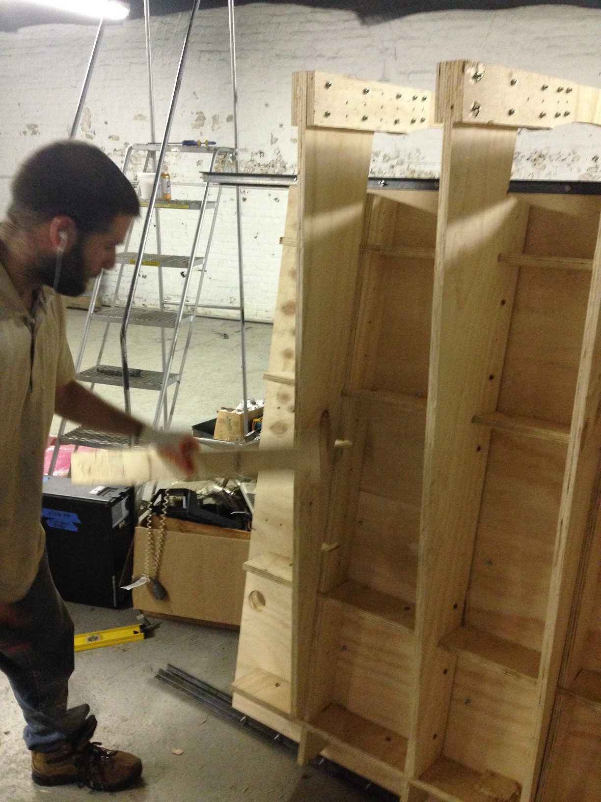
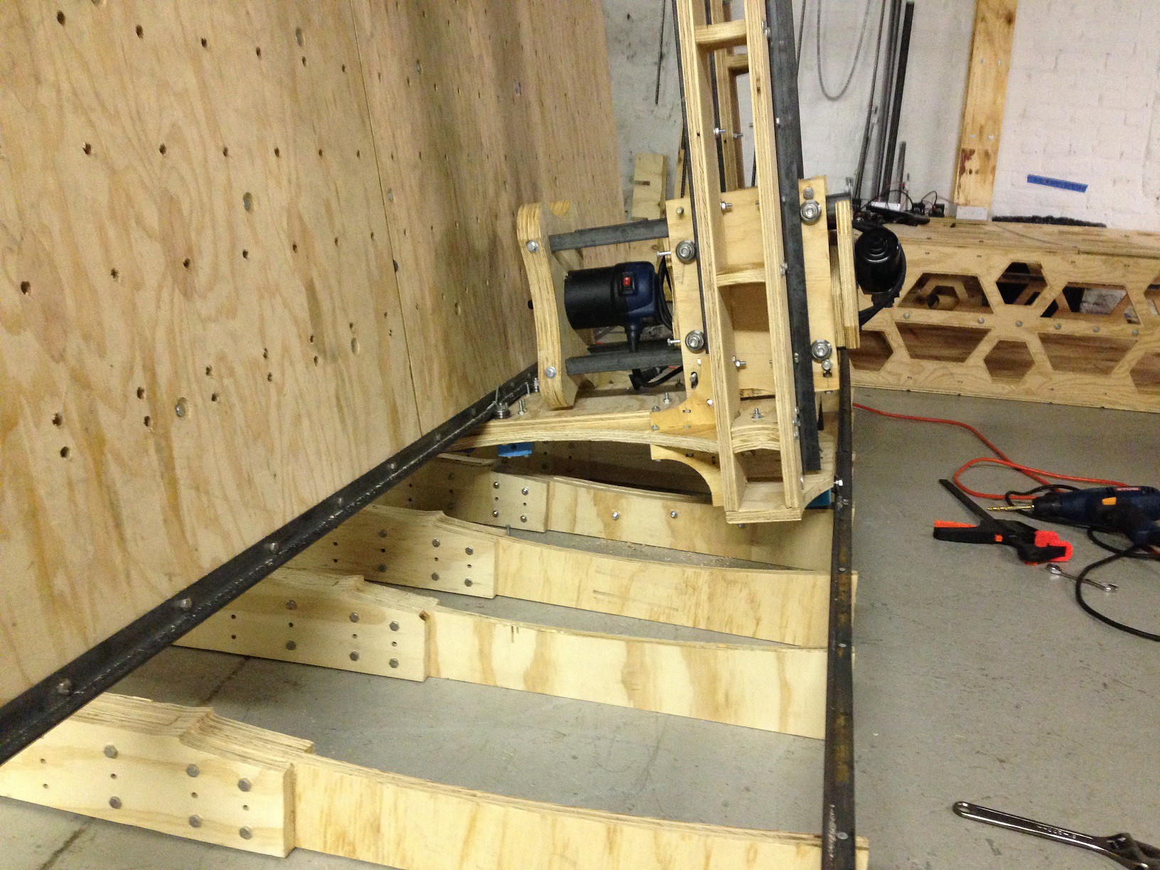
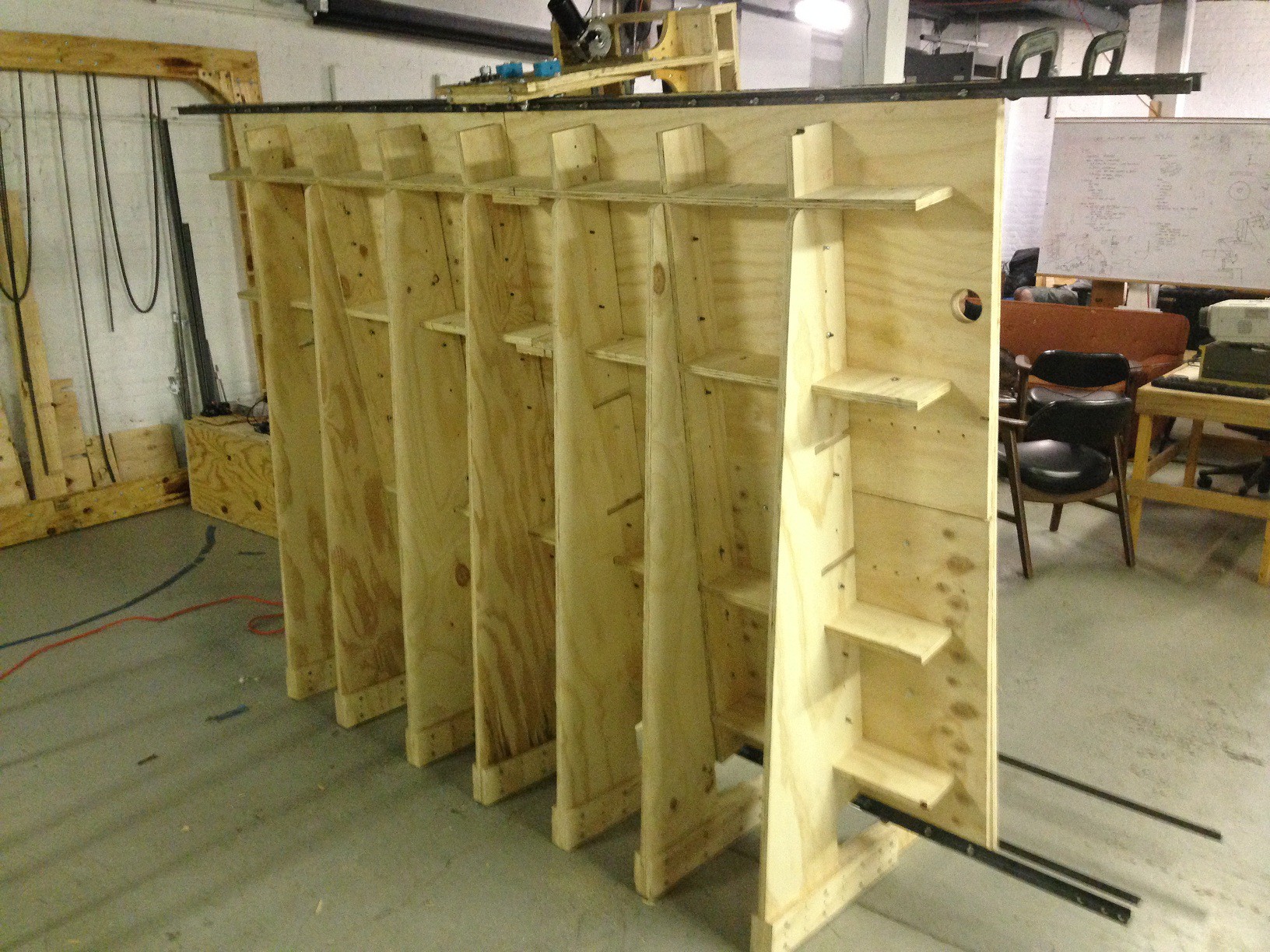
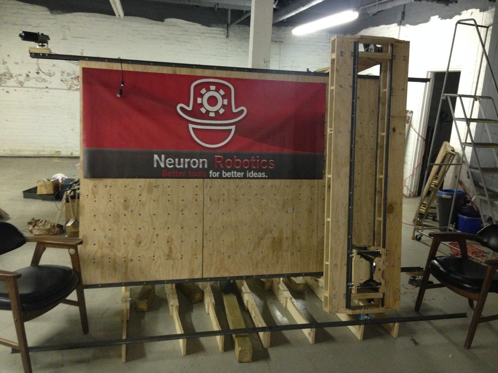
The machine is designed to stand in a vertical or horizontal position. This allows the mill to fit in a smaller footprint where required. The horizontal mill can easily be converted to vertical mill with only the addition of the supports.
Additional upgrades to come include a 5th axis head, Automatic Tool change, multiple y,z axis, reel to reel feeder, auto unload bed.
Milling:
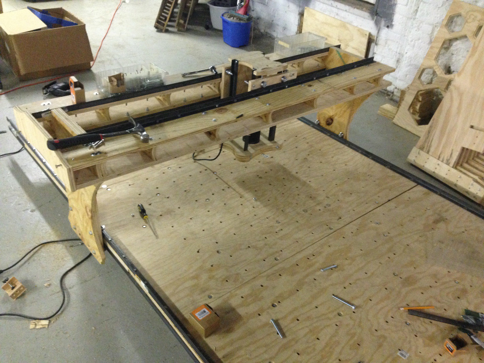
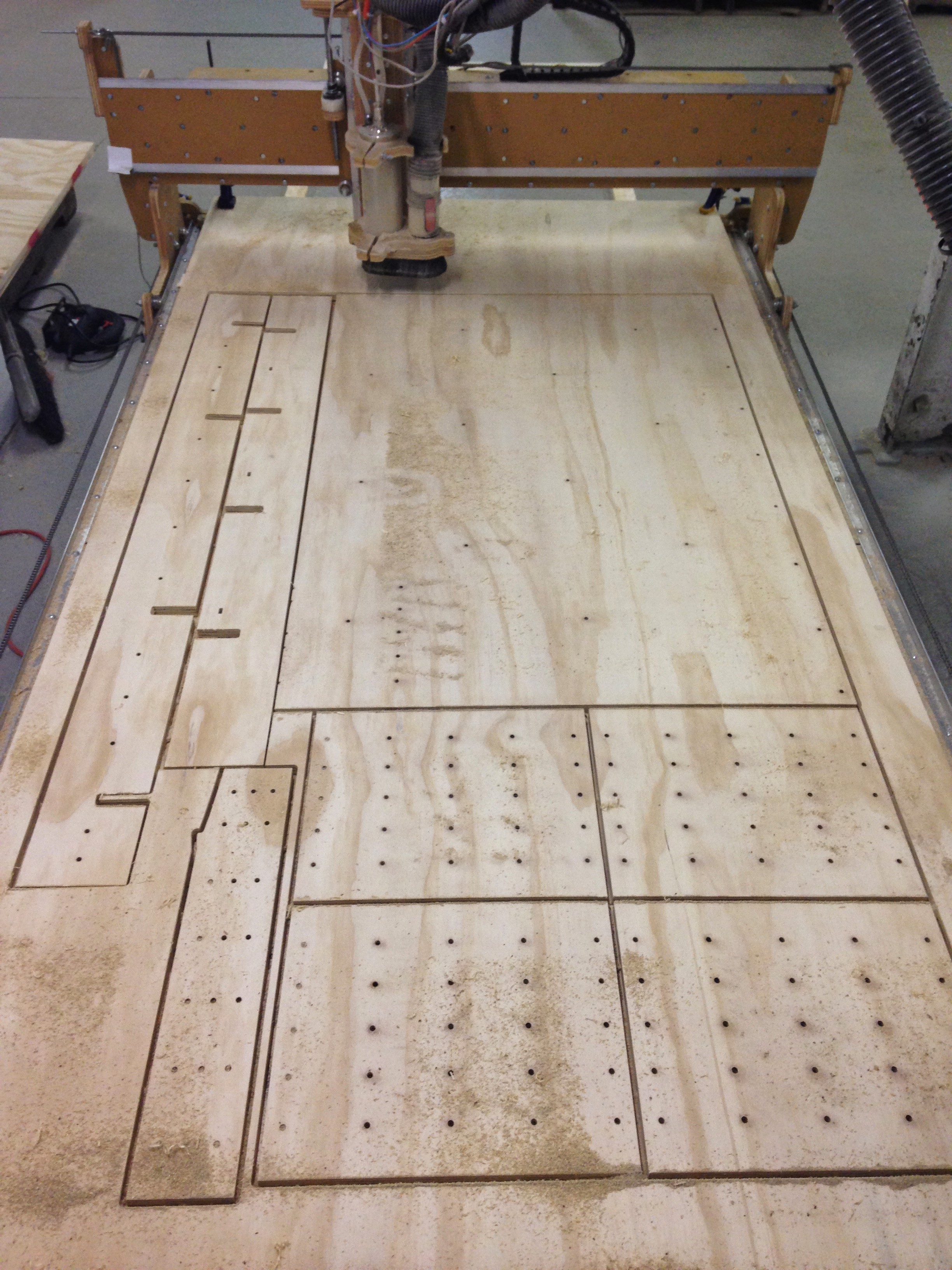
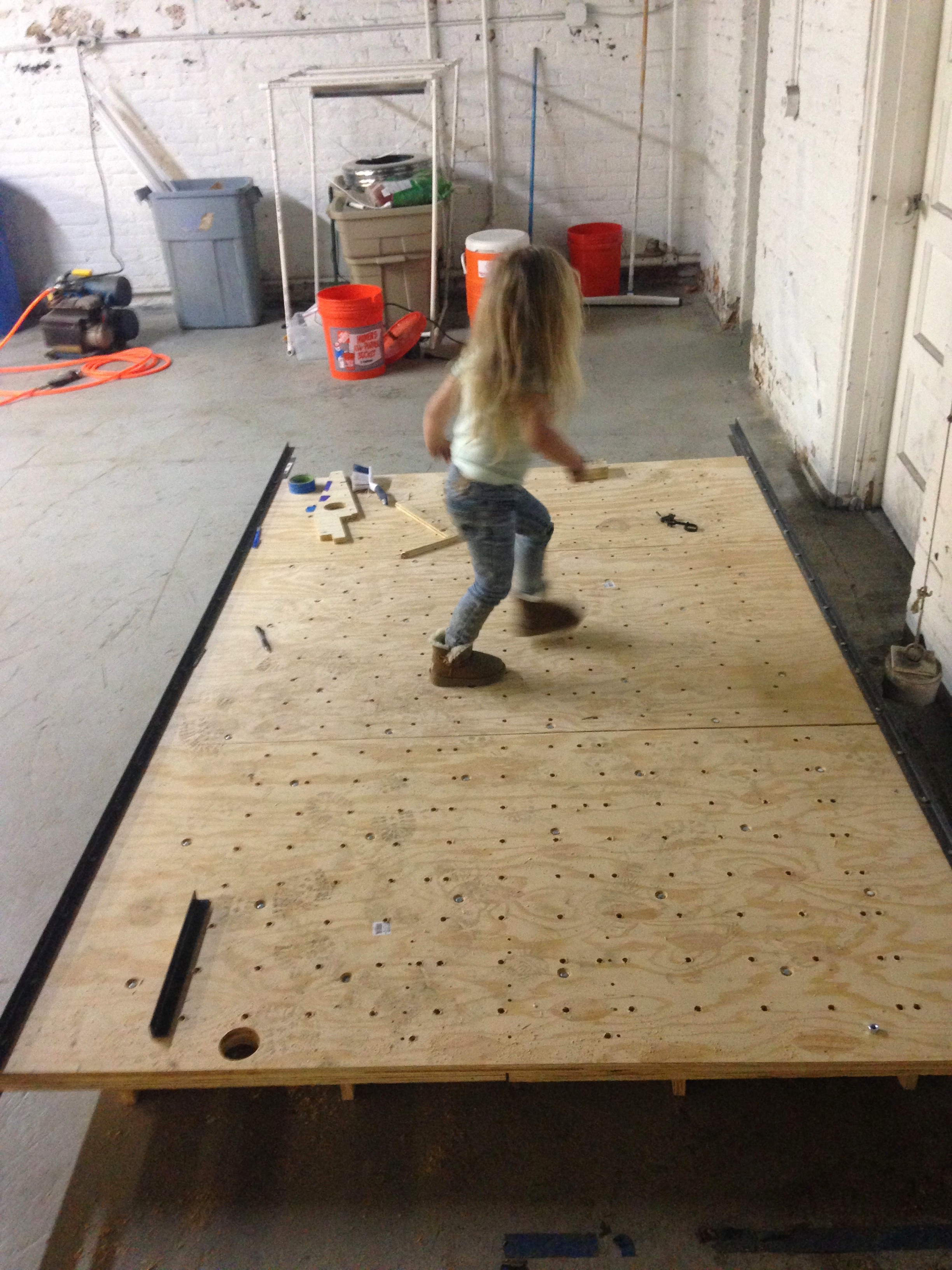
The bed of the machine is able to take a full 4'X8' sheet of plywood. It has clamp holes built into the bed to allow dimensional lumber to be bolted or clamped into place and milled. It also includes a vacuum table. This allows plywood to be held in place during cuts.
Lathe:
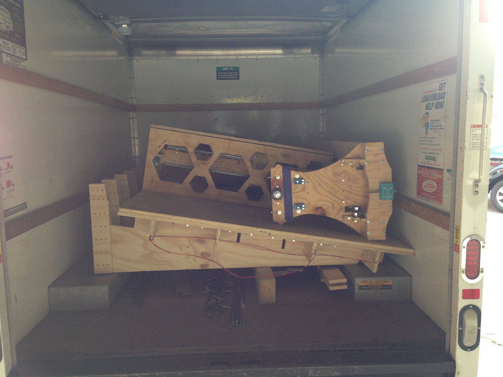
The lathe ends act as a 4th axis. It is controlled by a servo motor with encoder to allow precise cuts. It is able to easily removed or added as is desired.
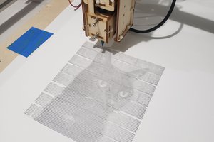
Laser:
A laser can be easily added to increase the functionality of the machine. The entire laser tube and optics are covered in either lexan, plywood or plastic. This creates a bubble around the beam for protection. In laser mode the z axis lowers to help protect the user from the beam. It is cabable of housing up to a 150 watt co2 laser. An additional feature we are currently working on is laser detection. This will disable the laser if the beam is not contacting the cutting area.
Once the machine has been assembled and tested all parts will be available open source under a creative commons license.
Software/Communications:
This project uses the same electronics hardware and software platform as the Servostock , laser cutter and open face mill..
http://hackaday.io/project/962-Servo-Stock
http://hackaday.io/project/1676-Open-Source-Laser-Cutter
http://hackaday.io/project/1698-Open-Face-Router
The system we developed over 4 years and have now applied to the flower router is an extensible, namespaced communication protocol. Think of it like a domain specific language over a generic serialized communication link. The protocol allows devices to report to the computer their capabilities, then the computer can generate packets based on that report. We have complete implementations in Java and C99. Clojure, Jython, Jruby and Matlab have been tested working with this library. There is a partial implementation in pure Ruby as well.
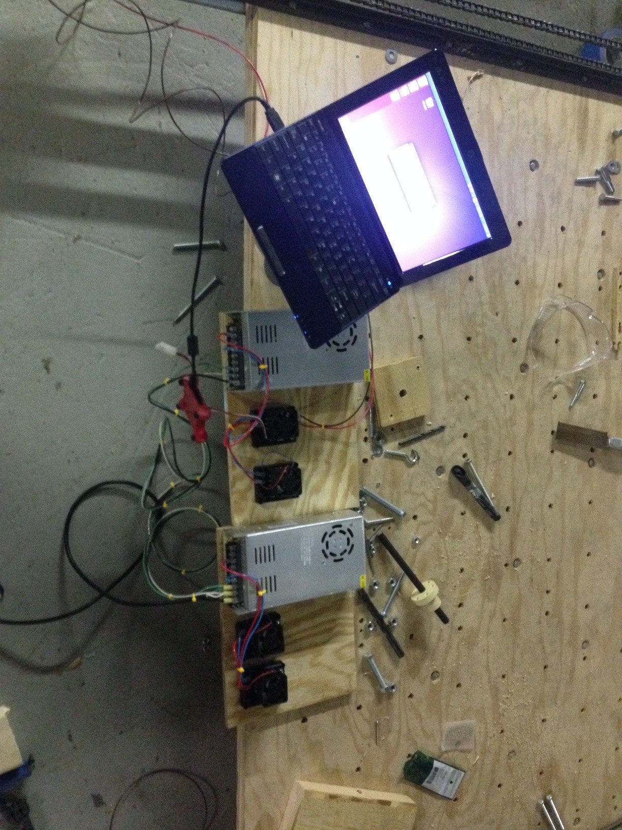
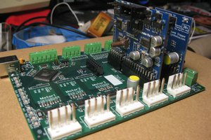
Electronics:
We have redesigned the entire control system from the ground up. From the get-go we started using magnet orientation encoders plus low cost continuous servos. The motherboard is a Pic32mx440f128h with each axis receiving a servo pulse and an SPI channel for the encoder. The motherboard uses a 7x2 ribbon cable to connect to each axis. Each axis has a small board with the encoder chip and the connector for the servo.
Firmware:
The control loop runs at 20 ms for the servo pulse calculation, interpolation and forward/inverse kinematics. The device identifies itself as having the PID control namespace, the kinematics namespace, and the router configuration namespace. Through the communication layer you can change kinematics models, change PID constants and store all the configurations. The configurations are stored non-volatile in Flash and travel with the printer to be read at runtime. NO MORE CONFIG FILES!!
The firmware also has auto-config system. The servo dead band is measured at boot time. The end stops are measured using the encoder with no limit switches.
Bootloader:
a (new to you guys) bootloader that i developed for the DyIO controller. It is a serial bootloader that uses the same communication protocol as the printer or any other device for that matter. The bootloading interface is just another namespace that any device can implement. The toolchain for generating bootloader...


 AVR
AVR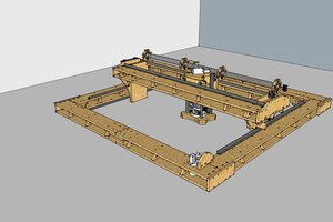
 John Opsahl
 MaximumMark