0%
0%
Designing a PROM Programmer for the 24S41
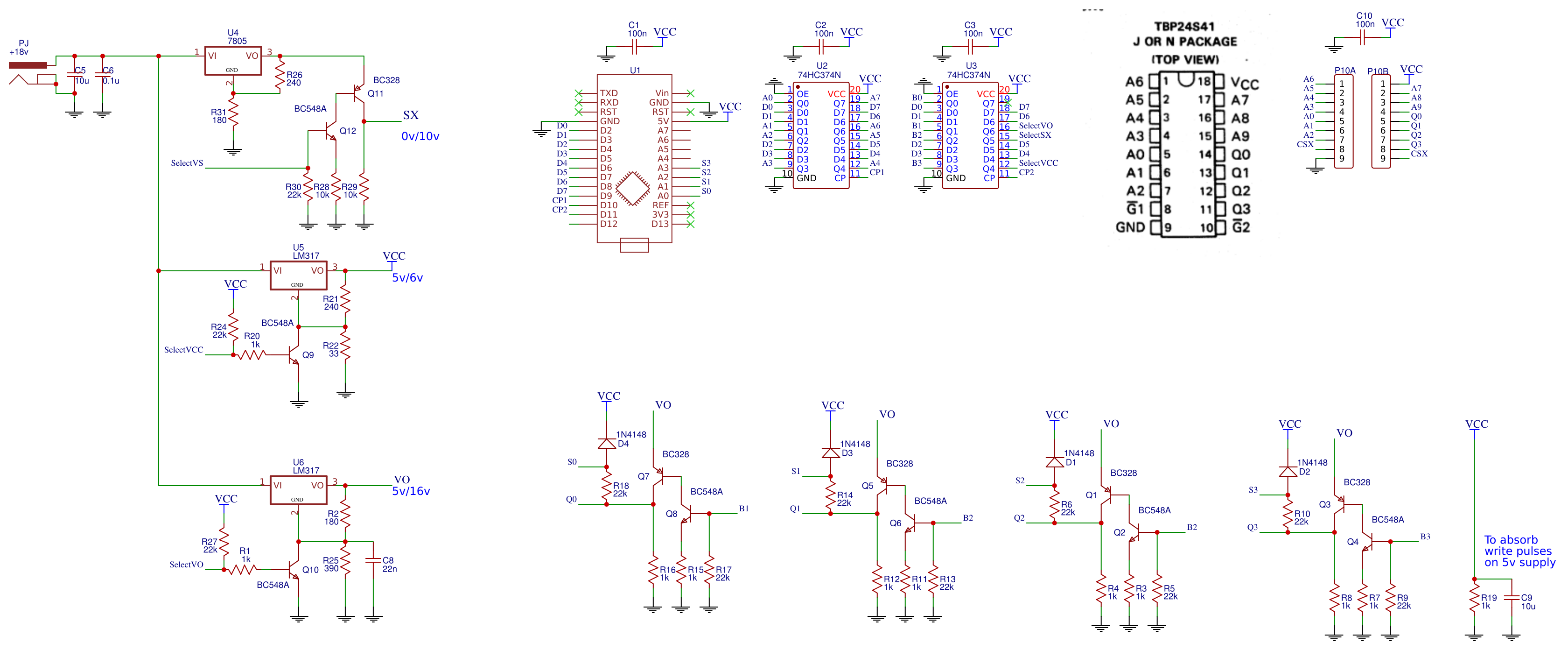
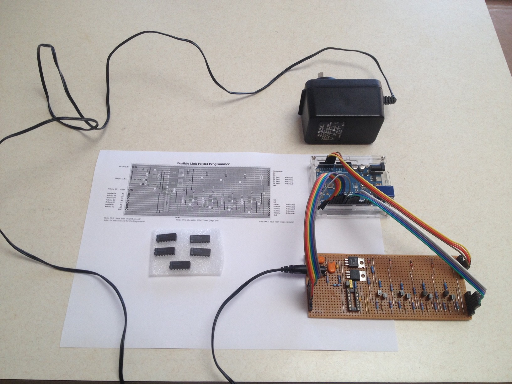
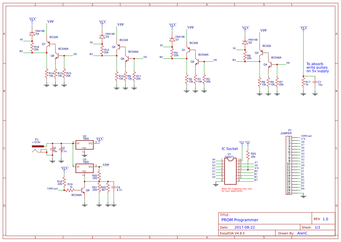
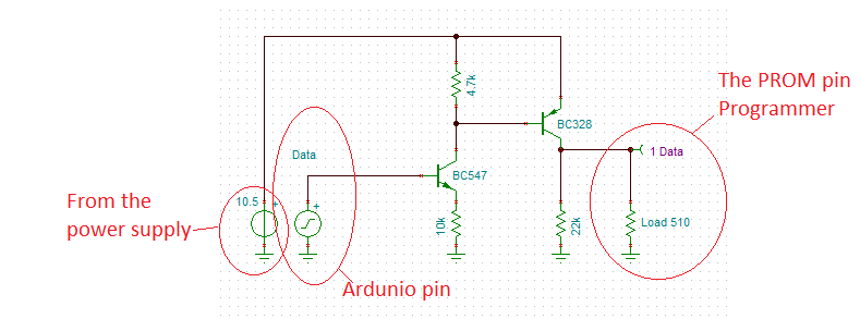
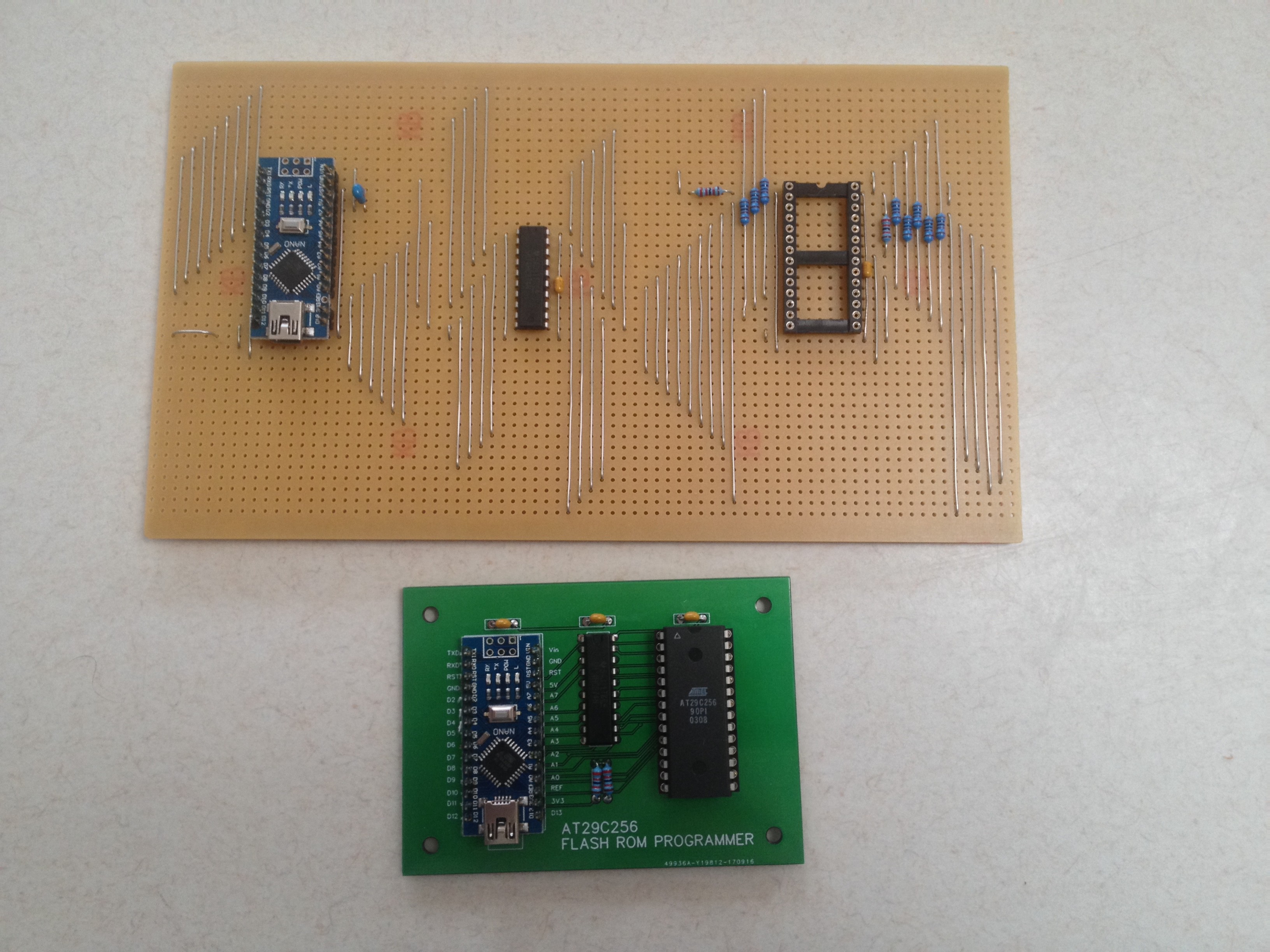
Danny approached me to help with building a programmer some 24S41 PROM chips for an Apple III restoration project.
 agp.cooper
Become a Hackaday.io member
Already have an account? Log in.
Just one more thing
To make the experience fit your profile, pick a username and tell us what interests you.
Pick an awesome username
hackaday.io/
Your profile's URL: hackaday.io/username. Max 25 alphanumeric characters.
Pick a few interests
Projects that share your interests
People that share your interests


 hamster
 Karl S
 Frédéric Druppel
 sjm4306
I have had practice with the 74S471 that I used for my Weird CPU. I wasted three out of five chips. One of them I mixed up by accident (over-wrote a good program). Still I know how you feel.
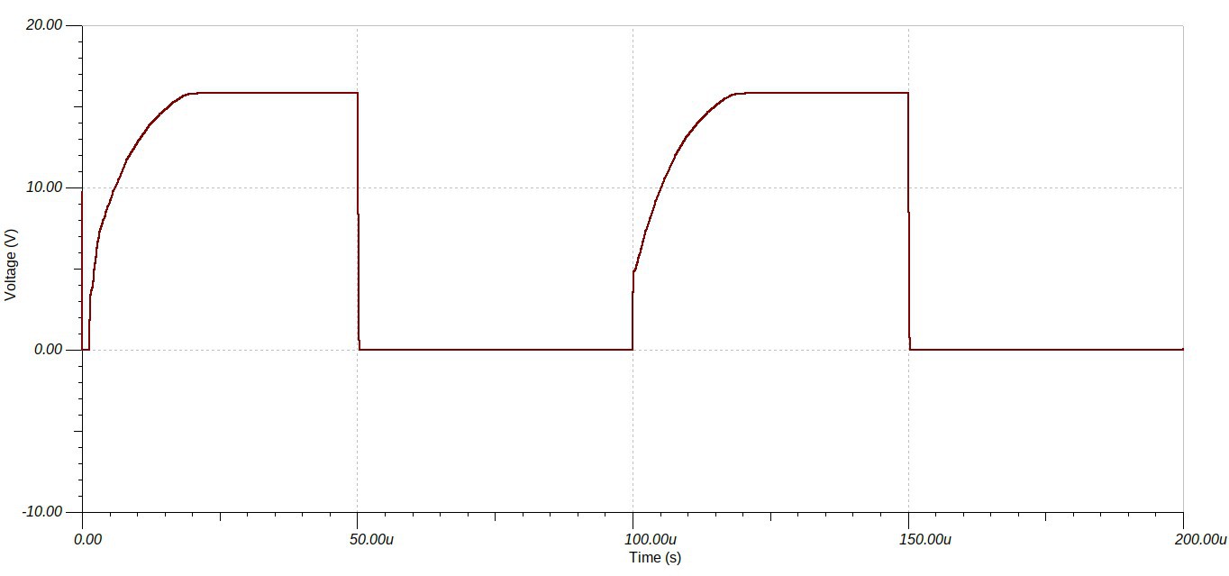
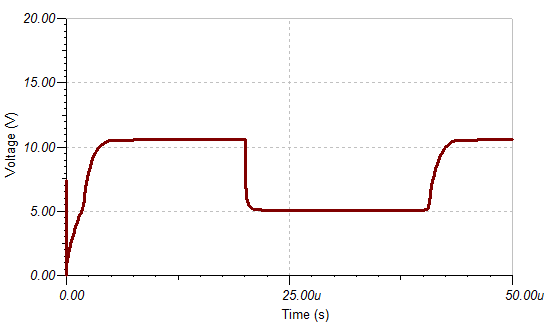
I simulate my code first using an Arduino that pretends to be the PROM (at a reduced speed).
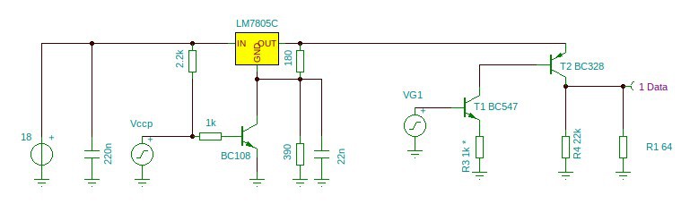
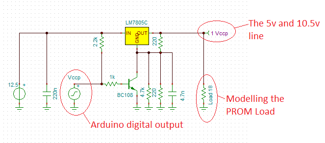
Anyway, I was going to use the LM317 to control the voltage steps but my simulations says it is too slow. I know the 78xx series is fast enough so I will have to use those.
AlanX