 aloismbutura
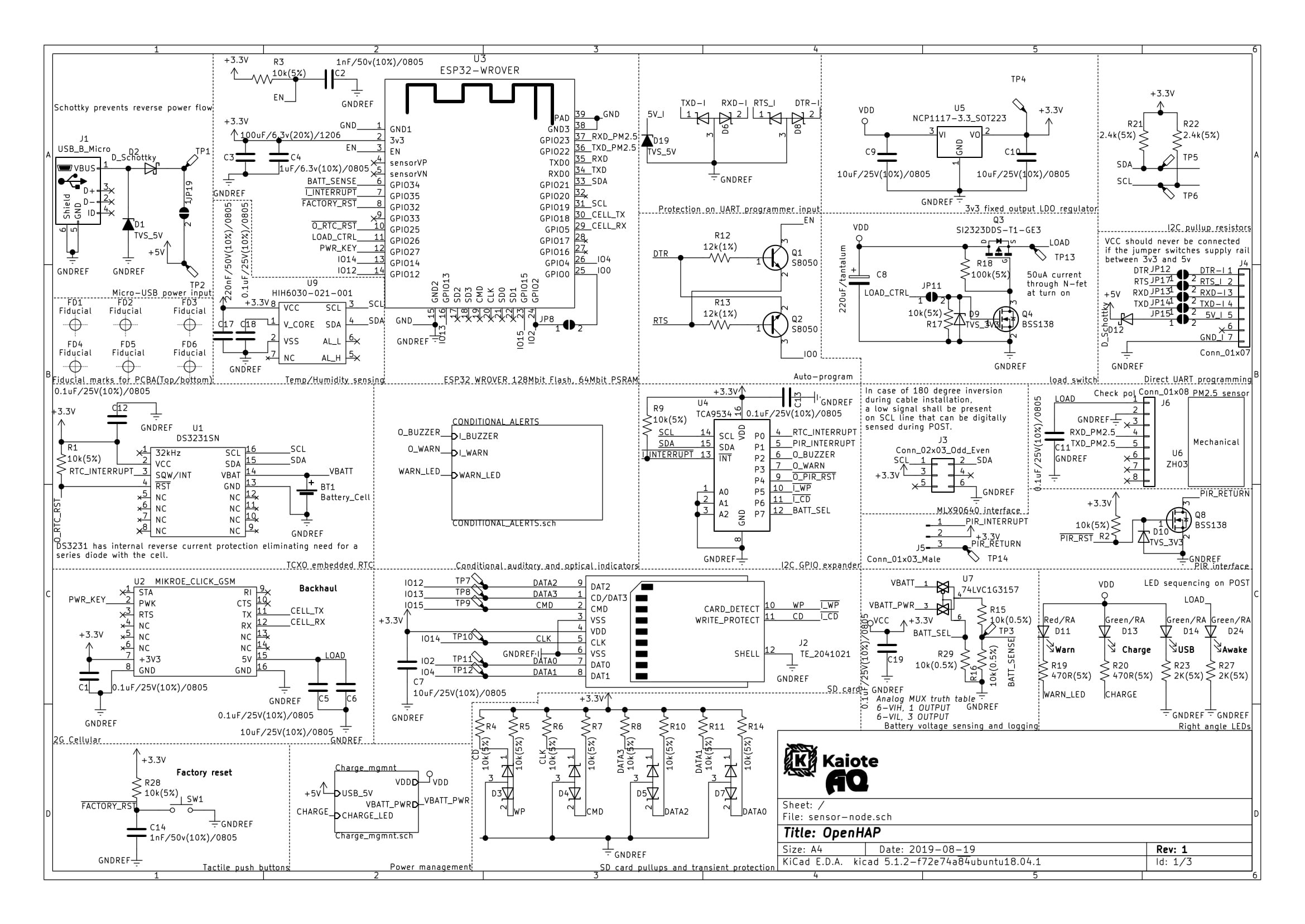
Power supply
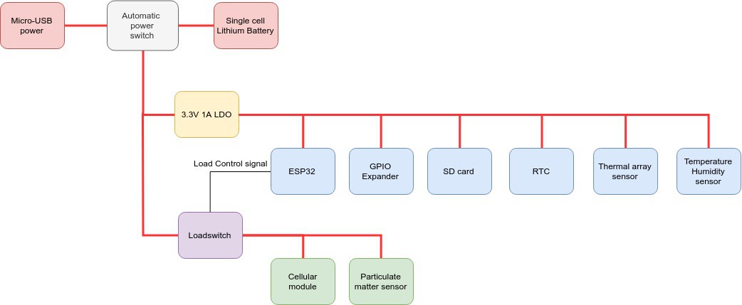
Load topology
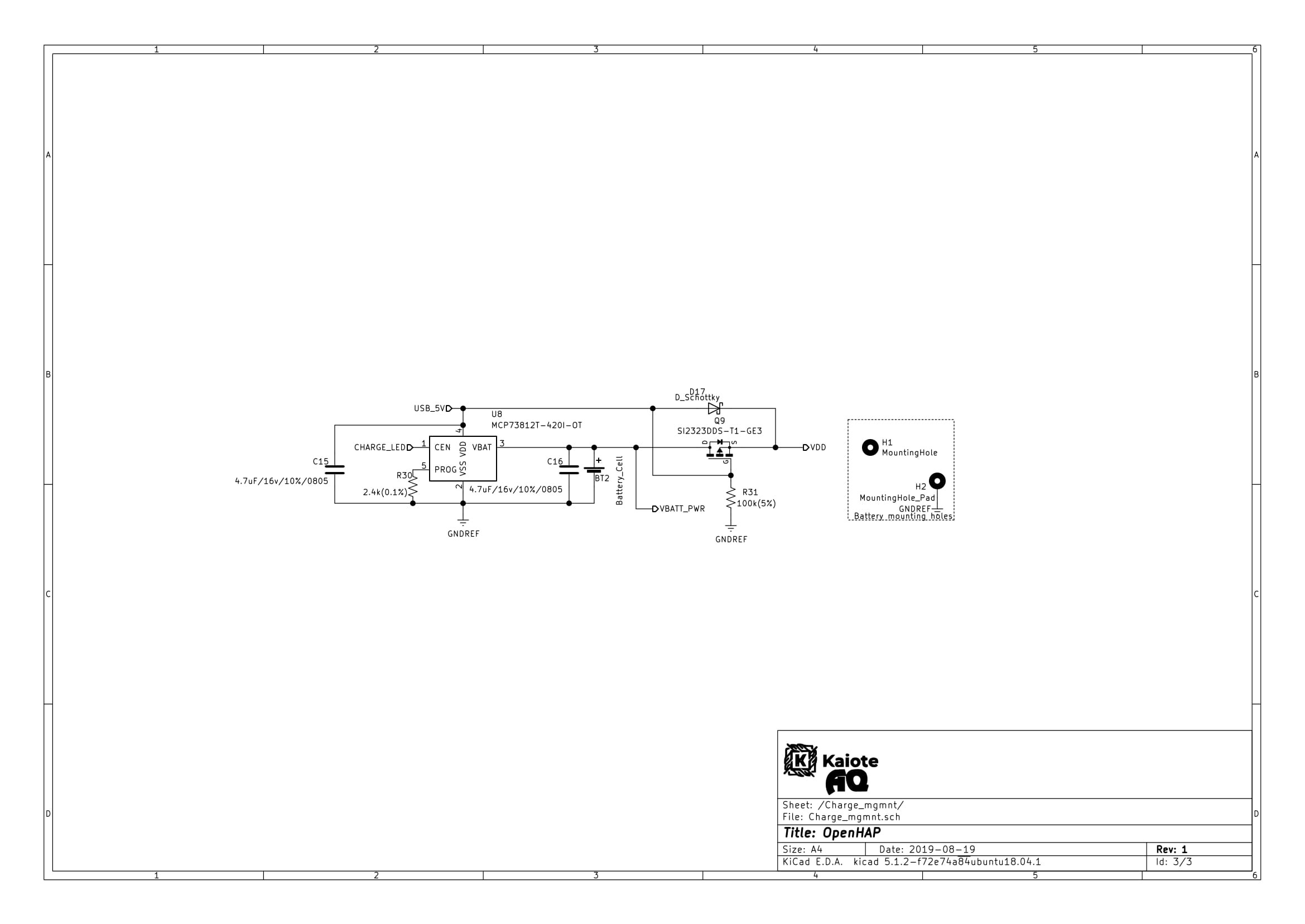
| Power input | Power management sheet |
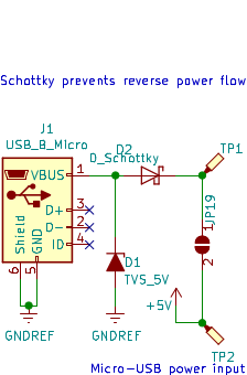 | 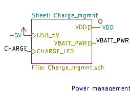 |
Power input is through a Micro-USB connector. The input is protected using a TVS diode and a schottky diode in series to prevent reverse power flow. The ~0.3v schottky diode forward voltage dropout is not too much of a concern as the power margin is relatively okay even with this loss at 5 volts input.
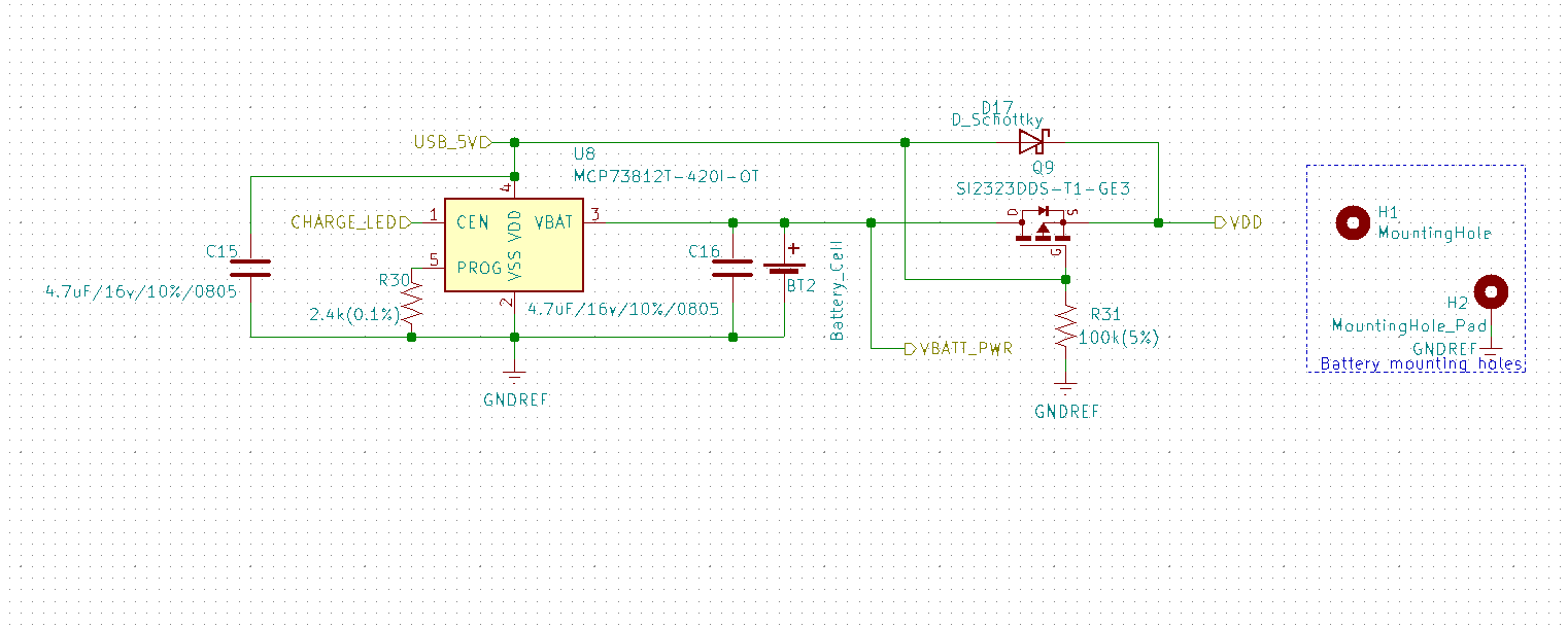
The power management circuit switches between power input via micro-USB and battery as well as handling the battery charging circuit. On removal of USB power, Transistor Q9 turns on, allowing the battery to be directly connected to the load via the VDD connection label above.Entire schematic
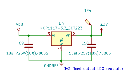
The VDD input is then regulated via LDO regulator to 3.3 volts that feeds the processor, GPIO expander, SD card, RTC, Humidity/temperature sensor. and the thermal sensor array.
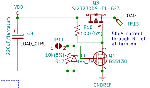
A load switch is added in order to control the load on the input power rail. This allows the processor to control power the Particulate matter sensor. The arrangement is in the Normally off state.
Processor
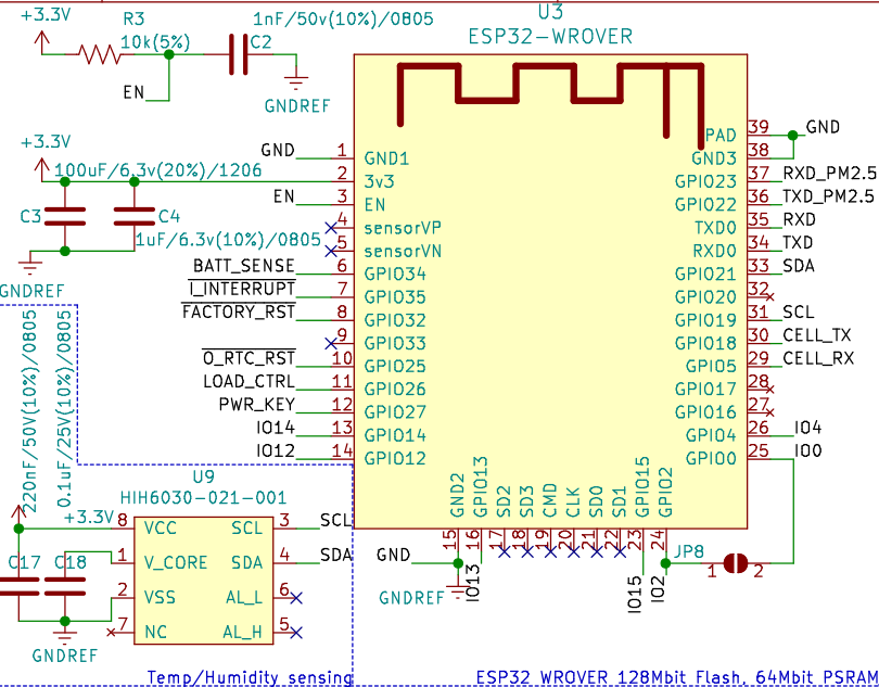
- The capacitor C2 connected to the EN label was erroneously left in the design. Its purpose in combination with the pull up resistor R3 on a connected mechanical switch(button) is to remove contact bounce causing erroneous resets.
- The power input is filtered through a parallel combination of 100uF and 1uF caps as mentioned in the datasheet.
- A solder jumper JP8 is added between "GPIO 0" and "GPIO 2" for testing ue to the following note:
GPIO2 pin is used as a bootstrapping pin, and should be low to enter UART download mode. One way to do this is to connect GPIO0 and GPIO2 using a jumper, and then the auto-reset circuit on most development boards will pull GPIO2 low along with GPIO0, when entering download mode.
Programming
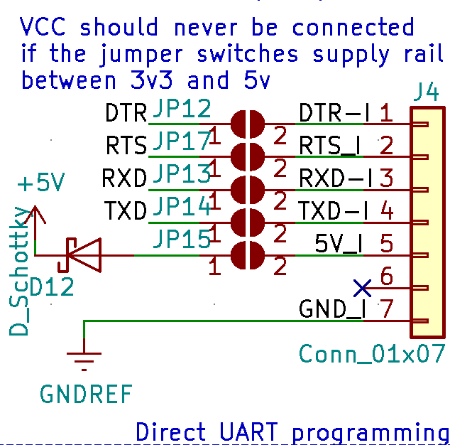
This port allows programming using an external programmer with the RTS and DTR lines exposed. In addition of a reverse A schottky diode is used to prevent/minimise reverse power flow.
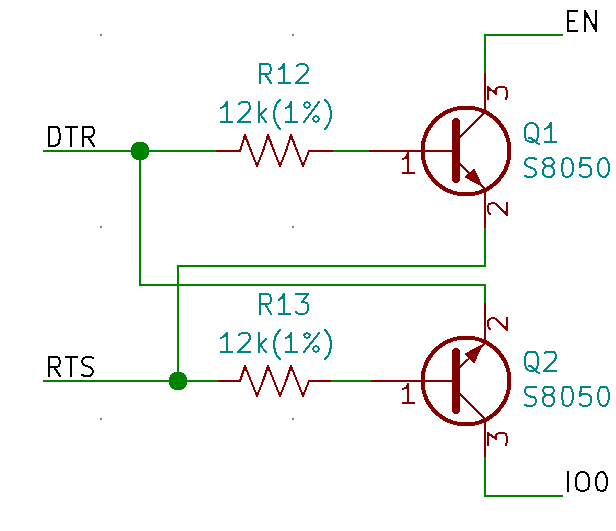
This circuit is documented within Espressif documents. It resets the chip automatically.
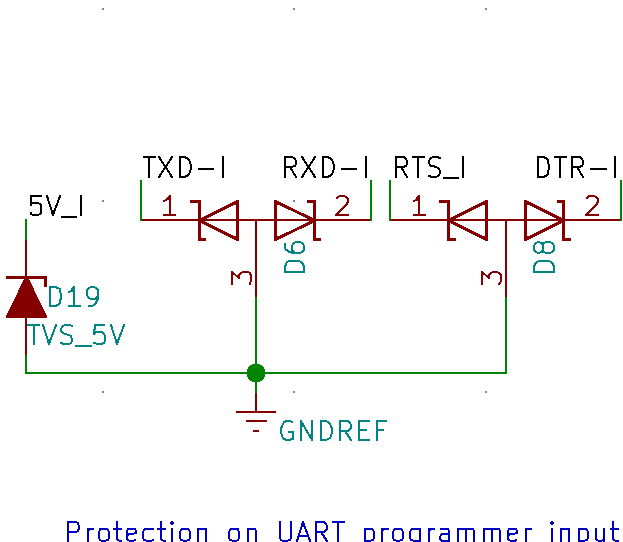
Transient protection on UART programming lines
Battery voltage sensing
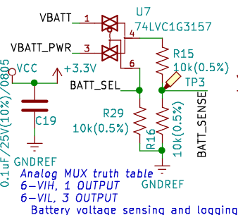
Battery voltage sensing is handled by the ADC through an analog multiplexer that is used to select between lithium battery voltage(VBATT_PWR) and the coin cell battery(VBATT) that powers the RTC in standby mode.
I2C bus pullups
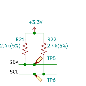
The IIC bus is fitted with 2.4k pull up resistors that would lead to allowably low rise and fall times due to the bus clock rates needed for the highest speed device on the bus, the MLX90640 2D thermal sensor array
TCA9534 GPIO expander
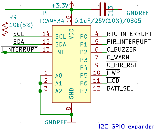
The GPIO expander is used to control the visual and auditory notifiers such as buzzer and LED. It is also used to interface to the SD card card detect and Write protect output lines as well as controlling the analog MUX within the battery voltage sensing section above.
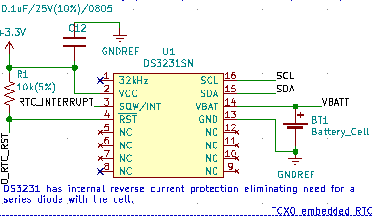
DS3231SN RTC
SD card
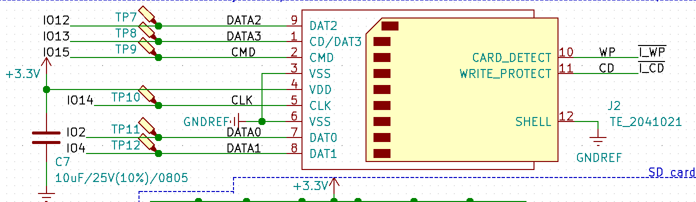
The SD card communication lines and power lines with test points.
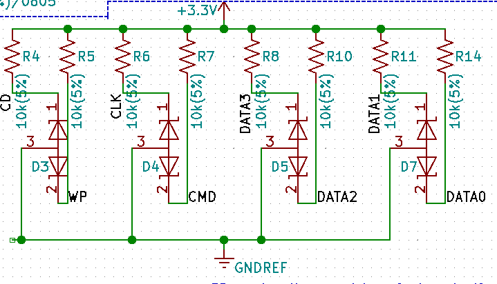
Transient protection and SD card communication line pullup resistors.
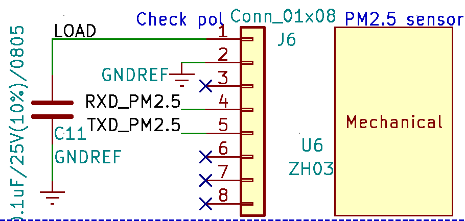
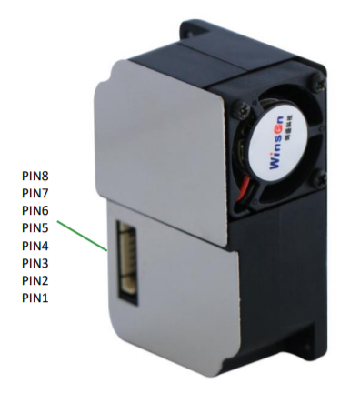
ZH03B Particulate matter sensor
 3D view of the main board and the MLX90640 add on board
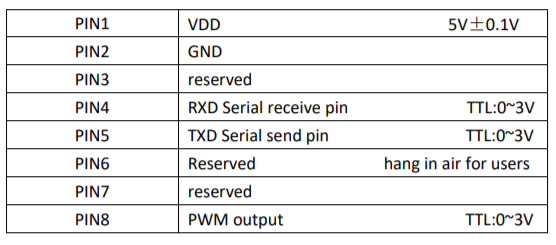
Note on ZH03 power requirements: The ZH03 datasheet states that the power should not deviate more than +/- 0.1 v over 5 volts but it has been tested that the particulate matter sensor supply can go below 3.7 volts-a typical lithium ion nominal voltage parameter, and still work okay. This means that it is okay powering the sensor directly from a lithium battery.
MLX90640 2D thermal array sensor
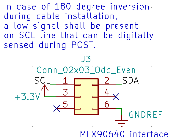
6 pin IDC connector on the main board
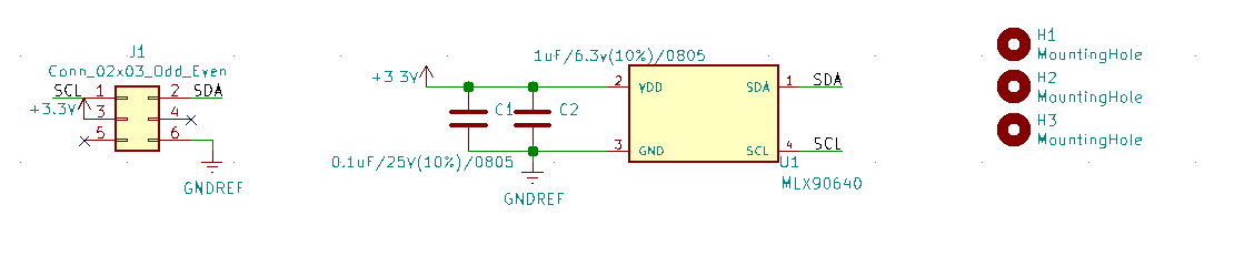
Add on board that contains the MLX90640 2D thermal array sensor with 6 pin IDC connector
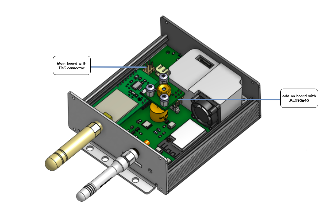
3D view of the main board and the MLX90640 add on board in situ
Fudicial markers
Discussions
Become a Hackaday.io Member
Create an account to leave a comment. Already have an account? Log In.