 Adam Taylor
Getting Started Building PYNQ
For this project we are going to be using the ZYBO Z7 board as the target for the PYNQ application. I picked this board as it provides six Pmod interfaces allowing us to interface with a range of sensors and actuators e.g. temperature, ambient light sensors, accelerators etc.
Of course the first step in this journey is to create a PYNQ image, which means we start our journey in Vivado where we implement the base hardware design.
To be able to make use of the Pmod interfaces the PYNQ framework uses Input Output Processors (IOP) within the programmable logic. These are Microblaze processors which are connected to a input / output switch to support several IO standards currently used e.g. IIC, SPI, UART, GPIO etc.
This lets us offload lower level, real-time interfacing to the programmable logic, enabling a more responsive solution.
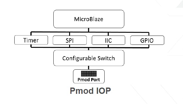
Concept Diagram
All of the IP needed to implement a IOP is provided within either the Xilinx IP or PYNQ IP library.
IOP Implementation in Vivado
To get started with the PYNQ image the first thing we needed to do is clone the PYNQ directory such that we can create the Vivado design and then later build the PYNQ Image.
We obtain the PYNQ framework from
git clone https://github.com/Xilinx/PYNQ.git
Once this is downloaded we can create the base application using the IP available within the /PYNQ/Boards/IP directory.
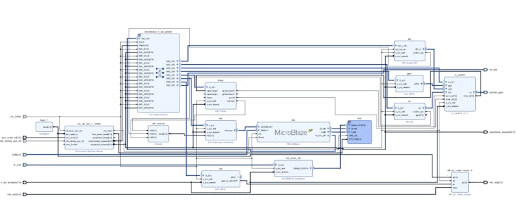
In this case the completed design for the Zybo Z7 board can be seen below and includes not only the IOPs but also GPIO for the buttons, switches, LEDS and three color LEDs.

Zybo Z7 Base PYNQ Design
A very important aspect of this solution is the use of the AXI interrupt controller to cascade the interrupts to the Zynq interrupt Generic Interrupt Controller.
Once the design has been completed we need to build the design in Vivado, and export the design so we can build a PetaLinux image.
Building PetaLinux
To build the PYNQ image we first need to create a PetaLinux BSP which means we need to create a new PetaLinux project and configure it for the hardware in Vivado.
If so far you created your Vivado design in Windows, to create both the PetaLinux image and the PYNQ image we need a Linux machine. To do these I use a Virtual Machine which uses Ubuntu 16.04 and has Petalinux and the PYNQ git repository downloaded on to it. If you are need a little more information on creating the build environmental check out this PYNQ Edition blog and Hackster Project
With the exported HDF from Vivado (Including the bitstream) available in the Linux build machine we need to run the following commands.
petalinux-create — type project — template zynq — name zybo
petalinux-config — get-hw-description Petalinux-build
Note once the hardware defintion is imported we will be presented with he PetaLinux project configuration dialog. As we do not need to make any changes then please just exit the dialog without saving anything. Building will take a few minutes.
Once the PetaLinux image is built the next step before we build the PYNQ image is to ensure the Linux image runs on the hardware. We can do this using the commands below
petalinux-boot –-jtag –-fpga
petalinux-boot –-jtag –-kernel
This will download the image to the Zybo board using the JTAG link and run up the image.
Once the boot is complete using a serial terminal we want to check that we can see the AXI GPIO in the LINUX device tree. From a command prompt we can run the command
dmesg
This will list the boot message and we can scroll through the message until we find the GPIO registration
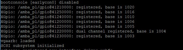
AXI GPIO Registration in PetaLinux
We can compare this against the memory map in Vivado and the addresses should be the same
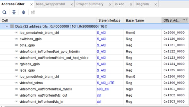
Vviado Memory Map
We can also connect to the Petalinux image over a network using SSH to ensure that interface is operational in the design. Once it is the next step is to prepare a BSP for the PYNQ image creation process.
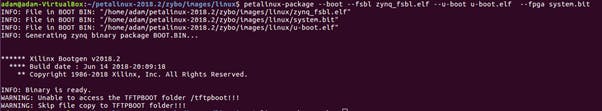
To do this we need t do two things first package the image then the BSP we use the commands
petalinux-package --boot --fsbl zynq_fsbl.elf --u-boot u-booot.elf --fpga system.bit
This will create the boot.bin needed to bot from a SDCard
Packaging the Image
Once the boot files are available the final step in PetaLinux is to create the BSP we do this by using the command
petalinux-package --bsp -p zybo -o zybo_pynq.bsp
NOTE to package the BSP we are outside of the PetaLinux project when we issue the command

Creating the BSP
With the BSP available we are now ready to create the PYNQ image
Creating the PYNQ Image
In our Linux build machine, with the Zybo BSP we are now able to build the PYNQ image. If you have not yet cloned the PYNQ repository on your build machine now is the time to do so.
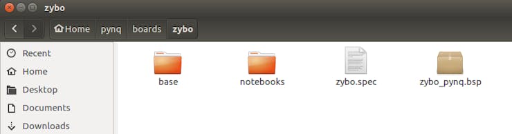
To create a new PYNQ image we are going to first need to create an new board definition in the folder pynq/boards

New Zybo Folder
Inside the ZYBO folder we are going to include the BSP, Bit file and a board definition
zybo specificaition
It is inside the Zybo specification file that we define the location of the bit file, bsp and architecture.
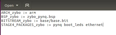
Zybo specification
If this is the first time we have run our PYNQ build machine we need to ensure it is set up correctly.
To do this we run the script set up host script under the pynq/sdbuild/scripts directory
source setup_host.sh
to build the image from within the pynq/sdbuild directory we run the command
make BOARDS=zybo
This will take a few minutes but once it is completed you will see the image available under
pynq/sdbuild/output
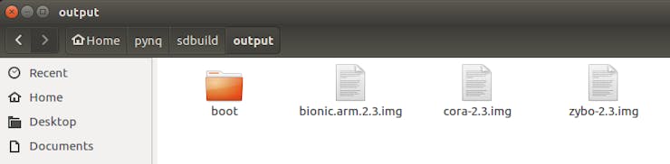
Output Images
We are now ready to start with the application development
Application Development
The application we are going to create is going will sample the ambient light level using a Pmod ALS and write this value to the cloud and then use IFTTT that turn on or off Phillips Hue lights.
To get started with this we are going to use the Adafruit.io cloud, this uses MQTT to work with it in our Python environment we need to install the adafruit.io library.
If you have not used adafruit.io before you will need to set up an account.
With an account created your secret AIO keys required to connect to your account can be found under the left hand side marked "View AIO Key". Protect these values from others but they will need to be included in our Python application.
The next step is to create the feed to which the Zybo will push data. Note, this feed name is the one we will use in our Zybo application and is case sensitive
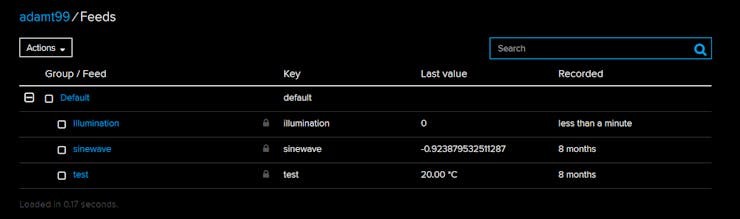
Setting up a feed
In the PYNQ environment we need to open up a terminal and install the adafruit.io packages using the command below.
pip3 install adafruit.io
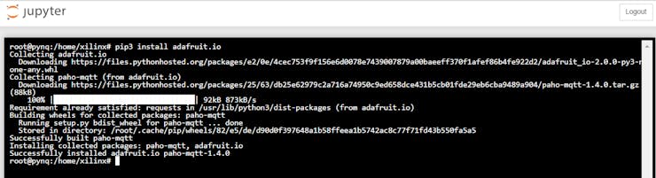
Downloading and Installing the Adafruit.io packages
Once we have downloaded this we can use these packages to push data to the cloud.
The application created in PYNQ notebook can be seen below, while very simple it enables us to implement a IoT based solution using the Adafruit cloud and IFTTT
from pynq.overlays.base import BaseOverlay
from pynq.lib import Pmod_ALS from Adafruit_IO import Client
import time
overlay = BaseOverlay("base.bit")
overlay.is_loaded()
aio = Client('NAME', 'ID') try:   while True:       illum = my_als.read()       aio.send('illumination', illum)       time.sleep(5)
except KeyboardInterrupt:       print("CTRL-C!! Exiting...")
The code will sample the ALS sensor every 5 seconds and push the sampled data to the Adafruit cloud as can be seen in the plots below.
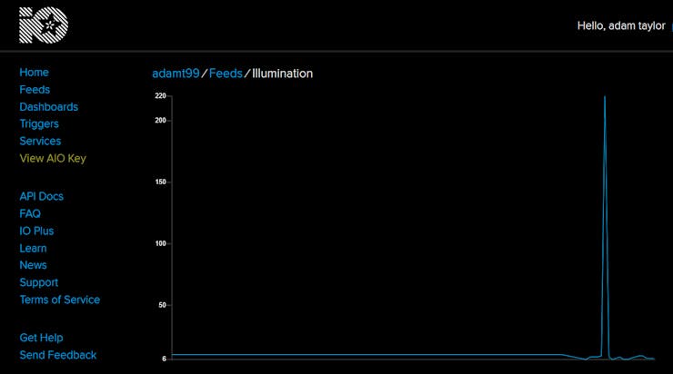
Plotting ALS data
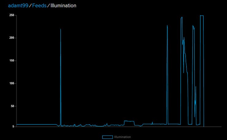
Plotting ALS Data with external illumination
To enable the observed value to take an end effect we use IFTTT which will monitor the adafruit.io cloud feed.
Depending upon the value in the feed the Phillips Hue light can then be turned either on or off.
IFTTT Configuration
To do this we need a IFTTT account, once we have an account we can create a new applet.
To use IFTTT with the feeds in our Adafruit IO account we need to enable IFTTT integration such that our IFTTT can access our feed. This can be enabled under your IO Adafruit profile, you may need to create an IFTTT account first to connect to it.
This is a six step process, the first thing we want to check is a service in this case it is Adafruit.

Once we have selected the Adafruit service we need to select the feed we wish to monitor and the relationship e.g. equal to, greater than, less than etc.

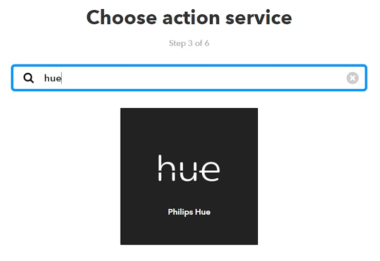
Once we have defined the relationship we need to be able to select the action service in this case it is Phillips Hue. To make ensure we can use the Phillips Hue with our application we do need to authorise IFTTT use in the Phillips Hue management application.
We can now choose the application we desire, e.g. turning a selected light on or off. This allows us to define two applets one to turn the light on if the ALS is below a set value, the other to turn the light off if it is above a set value.

Once we have identified if we wish to turn a light on or off we can select which exact light, a group of lights or all lights.

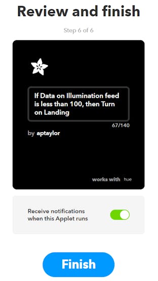
Once this is selected we have completed the applet creation.
Running this you will see the light turns on and off depending upon the illumination the ALS is subject too. To change the ALS value I used the flashlight (tourch) built in function on my mobile phone.
Wrap Up
This project shows the ease with which we can adapt the PYNQ framework to a new board, and get up and running with frameworks which allow us to create IoT applications easily.
Getting Started Building PYNQ
For this project we are going to be using the ZYBO Z7 board as the target for the PYNQ application. I picked this board as it provides six Pmod interfaces allowing us to interface with a range of sensors and actuators e.g. temperature, ambient light sensors, accelerators etc.
Of course the first step in this journey is to create a PYNQ image, which means we start our journey in Vivado where we implement the base hardware design.
To be able to make use of the Pmod interfaces the PYNQ framework uses Input Output Processors (IOP) within the programmable logic. These are Microblaze processors which are connected to a input / output switch to support several IO standards currently used e.g. IIC, SPI, UART, GPIO etc.
This lets us offload lower level, real-time interfacing to the programmable logic, enabling a more responsive solution.
Concept Diagram
All of the IP needed to implement a IOP is provided within either the Xilinx IP or PYNQ IP library.
IOP Implementation in Vivado
To get started with the PYNQ image the first thing we needed to do is clone the PYNQ directory such that we can create the Vivado design and then later build the PYNQ Image.
We obtain the PYNQ framework from
git clone https://github.com/Xilinx/PYNQ.git
Once this is downloaded we can create the base application using the IP available within the /PYNQ/Boards/IP directory.
In this case the completed design for the Zybo Z7 board can be seen below and includes not only the IOPs but also GPIO for the buttons, switches, LEDS and three color LEDs.
Zybo Z7 Base PYNQ Design
A very important aspect of this solution is the use of the AXI interrupt controller to cascade the interrupts to the Zynq interrupt Generic Interrupt Controller.
Once the design has been completed we need to build the design in Vivado, and export the design so we can build a PetaLinux image.
Building PetaLinux
To build the PYNQ image we first need to create a PetaLinux BSP which means we need to create a new PetaLinux project and configure it for the hardware in Vivado.
If so far you created your Vivado design in Windows, to create both the PetaLinux image and the PYNQ image we need a Linux machine. To do these I use a Virtual Machine which uses Ubuntu 16.04 and has Petalinux and the PYNQ git repository downloaded on to it. If you are need a little more information on creating the build environmental check out this PYNQ Edition blog and Hackster Project
With the exported HDF from Vivado (Including the bitstream) available in the Linux build machine we need to run the following commands.
petalinux-create — type project — template zynq — name zybo
petalinux-config — get-hw-description Petalinux-build
Note once the hardware defintion is imported we will be presented with he PetaLinux project configuration dialog. As we do not need to make any changes then please just exit the dialog without saving anything. Building will take a few minutes.
Once the PetaLinux image is built the next step before we build the PYNQ image is to ensure the Linux image runs on the hardware. We can do this using the commands below
petalinux-boot –-jtag –-fpga
petalinux-boot –-jtag –-kernel
This will download the image to the Zybo board using the JTAG link and run up the image.
Once the boot is complete using a serial terminal we want to check that we can see the AXI GPIO in the LINUX device tree. From a command prompt we can run the command
dmesg
This will list the boot message and we can scroll through the message until we find the GPIO registration
AXI GPIO Registration in PetaLinux
We can compare this against the memory map in Vivado and the addresses should be the same
Vviado Memory Map
We can also connect to the Petalinux image over a network using SSH to ensure that interface is operational in the design. Once it is the next step is to prepare a BSP for the PYNQ image creation process.
To do this we need t do two things first package the image then the BSP we use the commands
petalinux-package --boot --fsbl zynq_fsbl.elf --u-boot u-booot.elf --fpga system.bit
This will create the boot.bin needed to bot from a SDCard
Packaging the Image
Once the boot files are available the final step in PetaLinux is to create the BSP we do this by using the command
petalinux-package --bsp -p zybo -o zybo_pynq.bsp
NOTE to package the BSP we are outside of the PetaLinux project when we issue the command
Creating the BSP
With the BSP available we are now ready to create the PYNQ image
Creating the PYNQ Image
In our Linux build machine, with the Zybo BSP we are now able to build the PYNQ image. If you have not yet cloned the PYNQ repository on your build machine now is the time to do so.
To create a new PYNQ image we are going to first need to create an new board definition in the folder pynq/boards
New Zybo Folder
Inside the ZYBO folder we are going to include the BSP, Bit file and a board definition
zybo specificaition
It is inside the Zybo specification file that we define the location of the bit file, bsp and architecture.
Zybo specification
If this is the first time we have run our PYNQ build machine we need to ensure it is set up correctly.
To do this we run the script set up host script under the pynq/sdbuild/scripts directory
source setup_host.sh
to build the image from within the pynq/sdbuild directory we run the command
make BOARDS=zybo
This will take a few minutes but once it is completed you will see the image available under
pynq/sdbuild/output
Output Images
We are now ready to start with the application development
Application Development
The application we are going to create is going will sample the ambient light level using a Pmod ALS and write this value to the cloud and then use IFTTT that turn on or off Phillips Hue lights.
To get started with this we are going to use the Adafruit.io cloud, this uses MQTT to work with it in our Python environment we need to install the adafruit.io library.
If you have not used adafruit.io before you will need to set up an account.
With an account created your secret AIO keys required to connect to your account can be found under the left hand side marked "View AIO Key". Protect these values from others but they will need to be included in our Python application.
The next step is to create the feed to which the Zybo will push data. Note, this feed name is the one we will use in our Zybo application and is case sensitive
Setting up a feed
In the PYNQ environment we need to open up a terminal and install the adafruit.io packages using the command below.
pip3 install adafruit.io
Downloading and Installing the Adafruit.io packages
Once we have downloaded this we can use these packages to push data to the cloud.
The application created in PYNQ notebook can be seen below, while very simple it enables us to implement a IoT based solution using the Adafruit cloud and IFTTT
from pynq.overlays.base import BaseOverlay
from pynq.lib import Pmod_ALS from Adafruit_IO import Client
import time
overlay = BaseOverlay("base.bit")
overlay.is_loaded()
aio = Client('NAME', 'ID') try:   while True:       illum = my_als.read()       aio.send('illumination', illum)       time.sleep(5)
except KeyboardInterrupt:       print("CTRL-C!! Exiting...")
The code will sample the ALS sensor every 5 seconds and push the sampled data to the Adafruit cloud as can be seen in the plots below.
Plotting ALS data
Plotting ALS Data with external illumination
To enable the observed value to take an end effect we use IFTTT which will monitor the adafruit.io cloud feed.
Depending upon the value in the feed the Phillips Hue light can then be turned either on or off.
IFTTT Configuration
To do this we need a IFTTT account, once we have an account we can create a new applet.
To use IFTTT with the feeds in our Adafruit IO account we need to enable IFTTT integration such that our IFTTT can access our feed. This can be enabled under your IO Adafruit profile, you may need to create an IFTTT account first to connect to it.
This is a six step process, the first thing we want to check is a service in this case it is Adafruit.
Once we have selected the Adafruit service we need to select the feed we wish to monitor and the relationship e.g. equal to, greater than, less than etc.
Once we have defined the relationship we need to be able to select the action service in this case it is Phillips Hue. To make ensure we can use the Phillips Hue with our application we do need to authorise IFTTT use in the Phillips Hue management application.
We can now choose the application we desire, e.g. turning a selected light on or off. This allows us to define two applets one to turn the light on if the ALS is below a set value, the other to turn the light off if it is above a set value.
Once we have identified if we wish to turn a light on or off we can select which exact light, a group of lights or all lights.
Once this is selected we have completed the applet creation.
Running this you will see the light turns on and off depending upon the illumination the ALS is subject too. To change the ALS value I used the flashlight (tourch) built in function on my mobile phone.
Wrap Up
This project shows the ease with which we can adapt the PYNQ framework to a new board, and get up and running with frameworks which allow us to create IoT applications easily.