Installing DesignStart FPGA
The first thing we need to do is create a DesignStart FPGA account, we can do this here.
Once registered you will receive an email, this email will contain the links to download Xilinx Vivado and crucially request an license key for Arm Keil

Registration Email Links
Clicking on the request key linkk will allow you to receive the Produce Serial Number, which is needed to generate a 90 day Arm Keil Essentials license.
With both Vivado and Arm Keil correctly installed and licensed, the next step is to download the reference M3 design for the Arty A7 which can be obtained here

DesignStart FPGA download
The downloaded Cortex-M3 will be contained within a compressed file, extract the compressed files until you see the following file structure.

File Structure for the extracted design
The next step is to set up Vivado such that we can work successfully with the example. The first step is to open Vivado and correctly set up a drive to enable Vivado to be able to work with the long path names in the directory strucutre.
Open Vivado and prior to opening the project in the TCL window enter the following commands. The installation directory is the path where you extracted the compressed file.
pwd cd <Installation Directory> exec subst V: .
This will map the installation directory to the drive V:\
With that we can open the Vivado project which you will find under
V:\hardware\m3_for_arty_a7\m3_for_arty_a7
Within Vivado if you open the block diagram you will see the Cortex-M3 block and the supporting IP including AXI GPIO, AXI UartLite, AXI BRAM Controller and AXI QSPI.

Reference Cortex-M3 design in Vivado
Development Flow
To create the Motor control application we need to use the following tools.
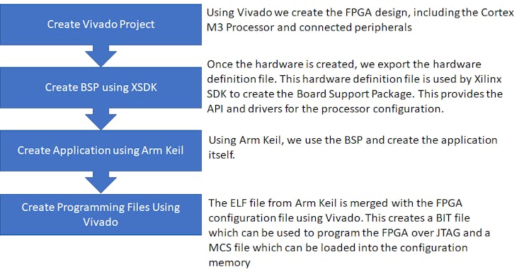
Cortex M3 Development Flow
Memory Map
The memory map of the Cortex-M3 design is as shown below, we will run our application from the ITCM which is the Instruction Tightly Coupled Memory.

Memory Map
Motor Control
This application will drive two wheels to allow the robot to navigate. To do so we need to be able to control the motor.
Unlike our other robotic projects (here and here) we will not be using servo motors but in there place we will be using Brushless DC Motors.
The motors in this application cannot be driven from a 3v3 logic supply like we use with the FPGA instead they will be using a higher voltage (10-12 volts). We will also need to be able to drive the motors in both forward and reverse.
To be able to supply higher voltages and control the direction of voltage flow across the motor we use a H Bridge configuration.
We use one H Bridge for each motor in the design, for this application the PmodHB3 will be used.
The two images below show the circuit diagrams for the PmodHB3 and the direction of voltage flow between the M+ and M- terminals.

H Bridge Voltage Flow for forward Motor Control

H Bridge Voltage Flow for Reverse Motor Control
The PmodHB3 is controlled using two GPIO, one which sets the direction and a enable signal which applies the voltage.
When we are working with this Pmod we must be VERY CAREFUL to ensure we do not change the direction while the enable is asserted. This will lead to creation of a short and has the potential for damage.
Updating the Vivado Design
As we are going to be using Pmods for Motor Control we need to have the Digilent Vivado library mapped in as an IP repository. If you do not have it you can obtain the repository here.
The PmodHB3 uses the PmogGPIO interface standard that is we can use GPIO signals to drive the PmodHB3. There are two signals we need to drive the direction and the enable.
The direction determines the voltage path through the H Bridge, while enable acts as a PWM based signal.

PmodHB3 Architecture.
To dive both motors we are...
Read more » Adam Taylor
 Stephane
 AdaCore
 Changyi Gu