 alexwhittemore
Before I get into the software that runs the tub, let's start with the hardware itself.
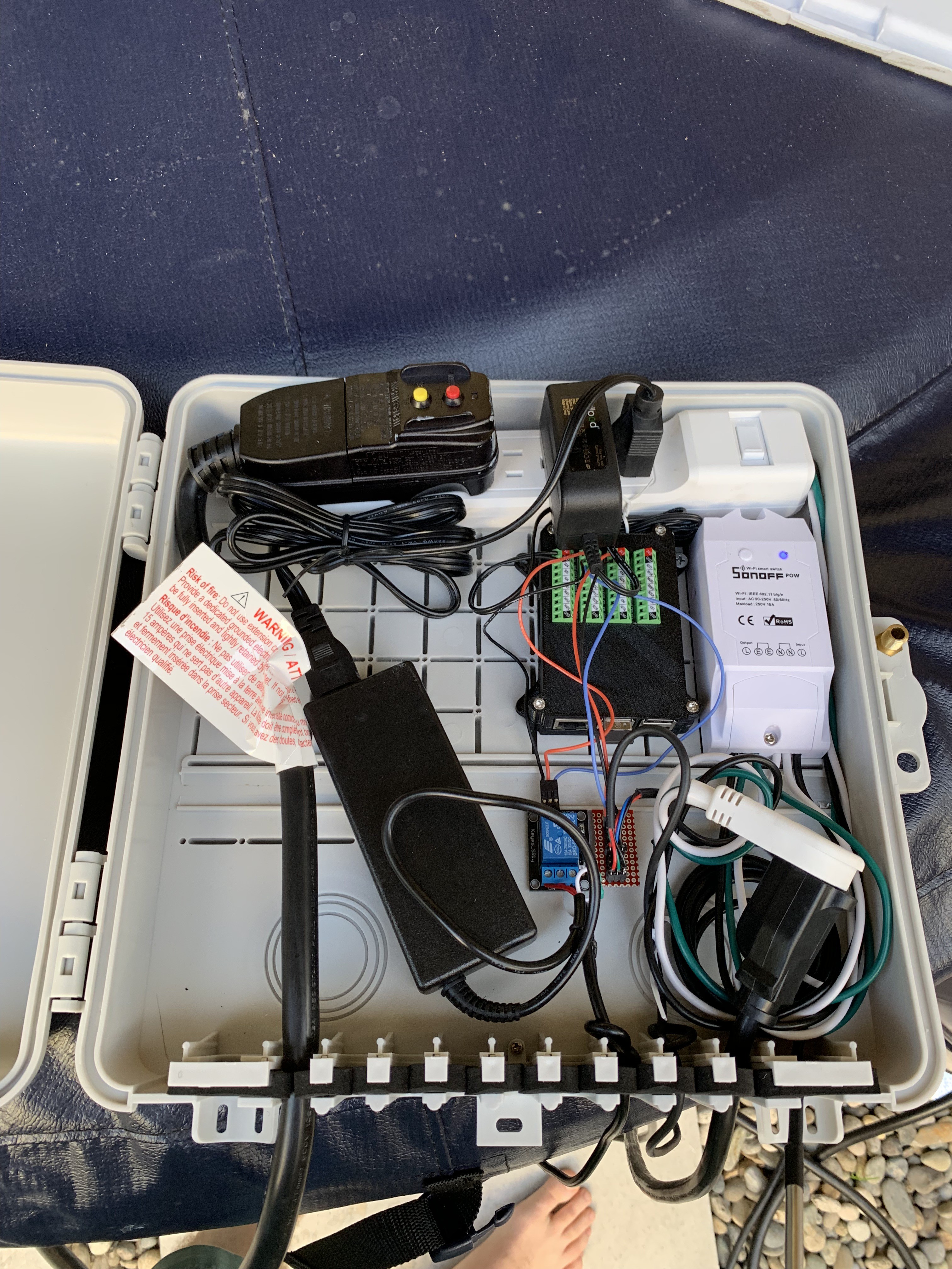
First of all, everything is housed in a reasonably splash-proof weatherproof enclosure from Extreme Broadband. It turns out, these broadband cable enclosures are excellent. They're designed for flexibility so a cable installer can easily and quickly toss in whatever needs installing. They're meant to be used outside, so they've got reasonable water ingress measures like gaskets around cable entries and a double-lipped closure that should well keep out rain and hot tub splashing. And they're darn cheap. It was hard to find anything else at the $25 price point, even for simple boxes that would require manually drilling holes, installing cable glands, and all the rest of it.
As for stuff IN the box:
Sonoff Pow smart switch This is primarily for monitoring electrical power consumption. In long term use, I probably won't care about the power usage minute to minute, but at least in the beginning, I want to be able to measure real power usage as a means of determining thermal leakage power of the hot tub when I start modifying it. It's also useful to know what components draw what unavoidable power besides just the heater. For instance, leaving the circulation pump on full time is probably unnecessary, and while it pales in comparison to the heater, 50W on 100% duty cycle is still like $10/mo in electricity. I'm sure I'll be revisiting that number in the future. Beyond power measurement, the master switch is a good failsafe for shutting down the whole works if something's going wrong. If telemetry shows the tub is at 110F, for instance, it's nice to have a backup plan when VPNing into the house to bring up the controller interface doesn't work and I just WANT. IT. OFF. NOW.
Power strip Of course, everything needs power. The heater pump has a dedicated 12V 60W power supply, and the tub itself needs to be plugged in, all behind the Pow for the sake of monitoring. The Pi needs power too.
Temperature sensor junction block This one is actually interesting in its own right. Pictured here, a bus connects 4 DS18B20 temperature sensors in parallel to one IO pin on the Pi. When I eventually implemented all 4 in software, this kind of fell apart. I ended up putting a new distribution block in there that has an IO per sensor. I'll try to detail this experience in a later update.
Relay There's a single relay - an off the shelf board from one of the Chinese hobby electronics makers that just takes 5V, gnd, and a high impedance control signal, and has the relay driver circuit onboard. The relay switches the 12V power supply to the heater pump. I'd kind of like to switch AC power to the 12V supply instead, to eliminate parasitic draw of the power brick when the pump isn't in use. But that's a bit more dangerous, so I'll probably leave it for a future update once I have a chance to build a specific housing for the relay.
Raspberry Pi The brains of the show. The Pi has a couple electrical connections - one to the temperature sensors, and one to the relay that controls the heater pump. Recall that the flow switch in the camp shower ignites the burner, so this one relay controls whether the heater circuit is active at all. To make electrical connection easier and more mechanically robust, I'm using this screw terminal Pi hat from Amazon. Because the internet is awesome, someone's already come across the need for an enclosure for this very combination, and I'm using the case by "sneaks" over at Cults3D. In order to make it fit easily, I cut out all the plastic that fits between rows of terminals.
All of these components neatly screw into the grid of bosses in the broadband box designed for just that. The relay and 1-wire distribution block don't have cases, so I just hot glued them in place.
Most cables have been knotted internally for strain relief on the components.
Discussions
Become a Hackaday.io Member
Create an account to leave a comment. Already have an account? Log In.