 Cees Meijer
A remote controlled is nothing new, and a lot of the required electronics and controllers is widely available. But if you are not an Remote Controlled Vehicle (RC-)enthusiast, a lot of the words and abbreviations used on the HobbyKing RC pages are not immediately obvious.
First, I will need something to control the speed and direction of the thrusters. The motors are so-called 'brushless motors', which need special drive electronics. This is called an ESC or 'Electronic Speed Controller'. Then I found out after ordering my first pair of ESC's, not all ESC support changing the direction. Which makes sense if you use it to power a plane or helicopter. So I ordered a second (more expensive) pair 'with reverse'.
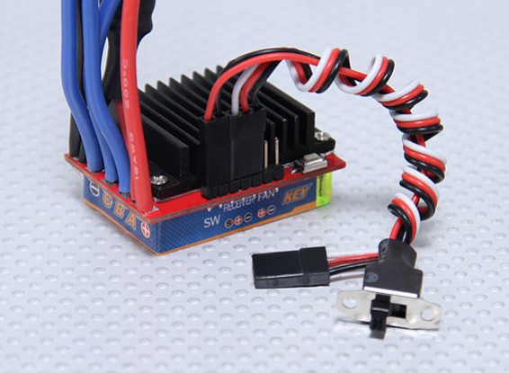
HobbyKing® ™ Brushless Car ESC 30A w/ Reverse
Specification:
Input voltage: 2-3S Lithium batteries / 4~9 Ni-xx
Cont. Current: 30A
BEC output: 2A /5V (Linear)
Now, as I said, I'm a newbie in RC, so first I did not know what 2-3S means. This appears to be the number of standard 3.7V Lithium cells as connected in Series. So '3S' is 11.1V. Next is the 'BEC Output'. BEC stands for Battery Eliminator Circuit. Which is not a device to actively destroy your batteries, but simply an on-board regulator that provides a regulated 5V DC for powering your external electronics so you do not need an additional power supply or battery for that. Great. Unfortunately the user manual is very extensive on the programming of this unit, but not very detailed on the connections.
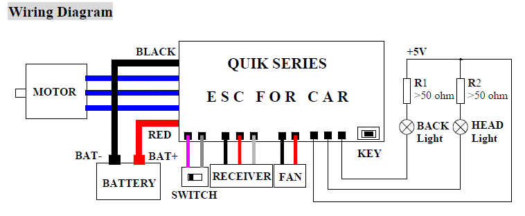
The contacts used for controlling the ESC are simply labelled 'RECEIVER'. Probably very obvious to anyone, except me. Now I think that the Red and Black wire are the BEC (5V) output, and the white wire probably carries the servo signal.
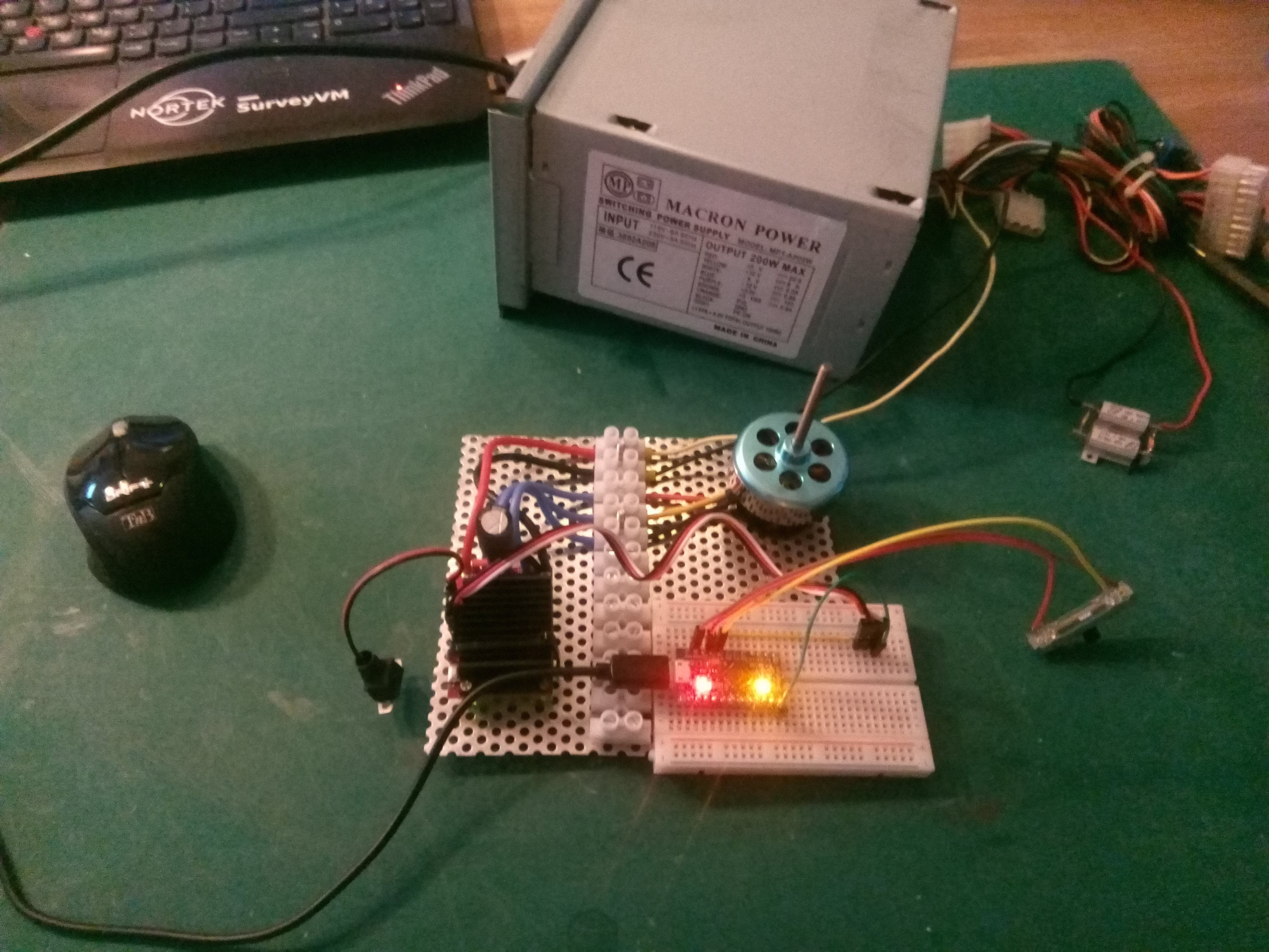
This is the test sketch:
int YaxisInput = A2;    // select the input pin for the potentiometer
int XaxisInput = A3;
int XValue,YValue;
int Motor1 = 9;
int Motor2 =10;

#include <Servo.h>
Servo ESC;     // create servo object to control the ESC

void setup() {
 pinMode(YaxisInput,INPUT);
 pinMode(XaxisInput,INPUT);
 ESC.attach(Motor1, 1000, 2000); // (pin, min pulse width, max pulse width in microseconds)
}

void loop() {
 XValue = analogRead(XaxisInput);
 YValue = analogRead(YaxisInput);
 XValue = map(XValue,0,1023,0,180);
 ESC.write(XValue);

Serial.print(XValue); Serial.print(",");  Serial.println(YValue);
delay(10);
}
And that works. After applying power, and switching the ESC on, it generates some 'beeps' using the motot itself which scared me at first.. But the beeps are an indication that the ESC detected the neutral throttle signal (the servo output from the arduino) and the power. After that, moving the potmeter controls the motor speed and direction just fine. Only when moving the controller too fast from one side to another so the reversal of the motor is very fast, the powersupply switches off. Probably the reverse current is too much for the powersupply protection.
Discussions
Become a Hackaday.io Member
Create an account to leave a comment. Already have an account? Log In.