Close
0%
0%

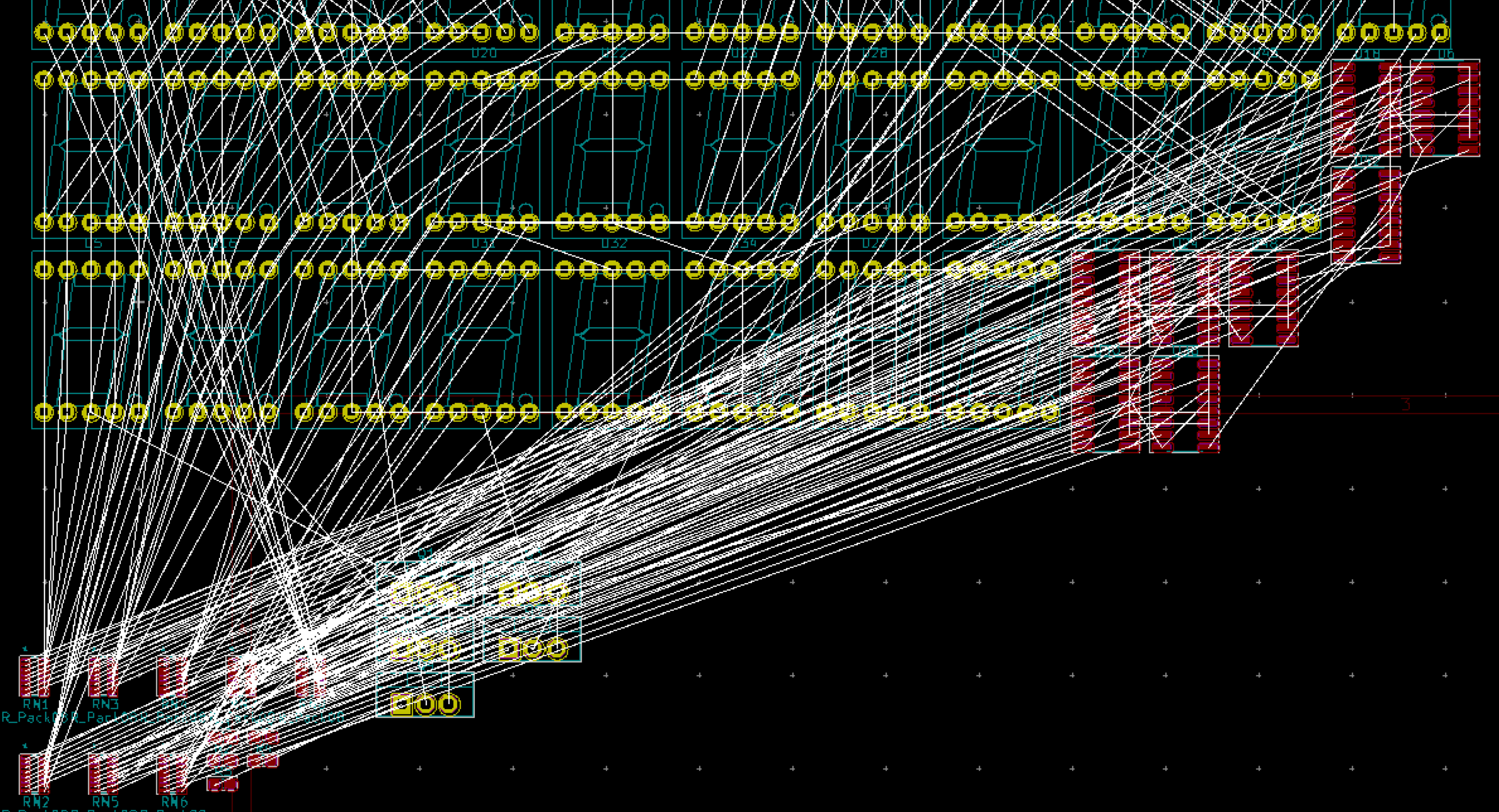
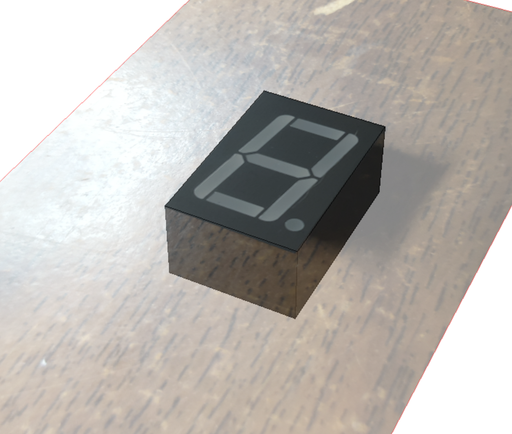
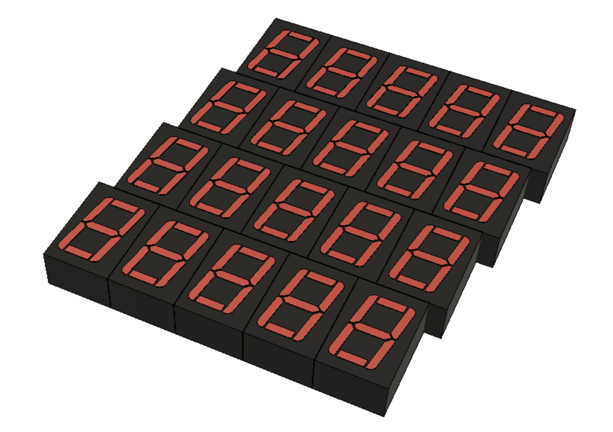
Snake on 7-segment displays

Might be very hard to play, but will look awesome!

Similar projects worth following
I bought 50 seven-segment displays for like eight cents each. Asked the Internet what to built and Antonio D'Amore (zombieprocess.it) suggested "Snake". I love it! Thanks Antonio!

Source is on github

  • PCB Layout

    Hari Wiguna08/28/2019 at 11:56 0 comments

    I got my work cut out for me...

    It took several tries to get to this:

    Lessons learned:

    1. Model the 3D file early.  It is easier to have the actual physical seven segment to play with rather than moving 40 of them after the fact.
    2. Move the parts to their places BEFORE laying traces.  There is a big chance you would need to move parts because of other parts - fixing traces sucks.
    3. Assign the 3D model in footprint editor -  NOT in PCBNew.
      • Footprint Editor > Load the footprint > Edit > Footprint Properties... > 3D Settings
      • Assign the 3D step file for this part
      • Translate and rotate to match the footprint

  • ESP8266 vs. ESP32

    Hari Wiguna08/17/2019 at 23:14 0 comments

    I had enable @micropython.native on the ESP8266 to get the best performance in refreshing the displays. 

    It turned out MicroPython for the ESP32 does not support that option!

    Either it is always on, or the ESP32 without that option is FASTER than the ESP8266 with that option.

    @micropython.native
    def shift_out(self, bits):
    for i in range(8):
            value = bits & (1 << i)  # Is bit set or cleared?
            self.data.value(1 if value > 0 else 0)
            self.clock.on()  # pulsing clock HIGH then LOW to shift data
            self.clock.off()

    This is faster!

    def shift_out(self, bits):
        for i in range(8):
            value = bits & (1 << i)  # Is bit set or cleared?
            if value > 0:
                self.data.on()
            else:
                self.data.off()
            self.clock.on()  # pulsing clock HIGH then LOW to shift data
            self.clock.off()

  • Seeing the invisible

    Hari Wiguna08/15/2019 at 04:21 2 comments

    I decided to go with the five rows of eight digits.

    So, each row is shifted through eight shift registers and shows up as 64 segments (counting the decimal points).

    This is what five rows of 64 bits look like on the scope.

    Yellow is the clock, blue is the data, and purple is the latch that is triggered as we switch rows.

    Zooming into the first row, lowest bit is high while the other bits are low because on first row we set leftmost digit to 1.

    zooming back out, after all 64 bits, you can see the "2" of the next row.

    You can see that this time, second bit is high, while the other bits are low.

    Subsequent rows are similar and on row 5, you can see the 0xFF as last 8 bits being shifted out.

    I wonder how many people read this.  Oh well, it was rewarding to see the bits set in a #MicroPython array refreshed by an independent timer so we're free to implement the snake without worrying about updating the display.

    Shift register code to do this test is on github.

  • Start designing PCB

    Hari Wiguna08/10/2019 at 15:08 3 comments

    Is it better to have five shift registers that we could shift faster than eight shift registers?

    Or is it better to display eight digits at a time, so each row would be "on" 1/5th of the time instead of 1/8th of the time?

  • Baby Step

    Hari Wiguna07/22/2019 at 06:14 0 comments

    I got one row wired up.

    Three GPIO pins for Shift Register clock, data, and latch.

    Six GPIO pins for each digit (column).  I'm out of GPIO except for the rx/tx and ADC.

    TODO: Insert code here

  • Mockup

    Hari Wiguna07/13/2019 at 22:33 0 comments

    I love Fusion360!

    I modeled one segment by tracing the segments on a canvas in Fusion360.

    Extrude the segments so I could set each segment color independently.

    Use rectangular pattern with a direction parallel with the digit slant.

    Then I used fill in Paint.NET to simulate lighting up various segments.

    All this before wiring, breadboarding, PCB, or coding!

View all 6 project logs

Enjoy this project?

Share

Discussions

Gerben wrote 07/17/2019 at 12:48 point

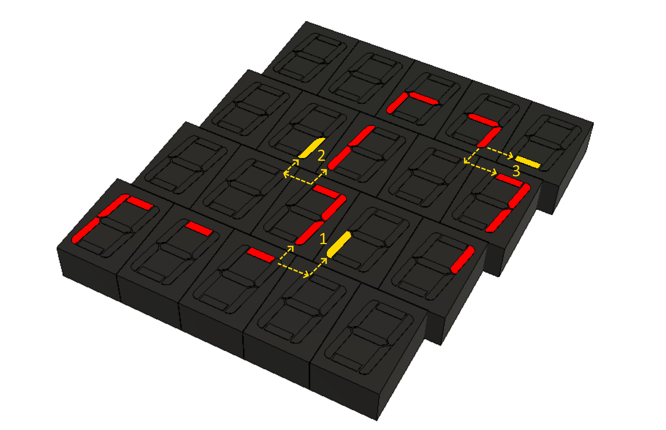
Will the decimal points be used for the Fruit?

  Are you sure? yes | no

Mike Szczys wrote 07/16/2019 at 21:26 point

Neat project! The mockup looks much better than I had exptects and I'm excited to see the first prototype. The slant of the segments is an interesting design challenge... offsetting the modules should make the overall appearance a bit more interesting.

  Are you sure? yes | no

Similar Projects

Does this project spark your interest?

Become a member to follow this project and never miss any updates