DISCLAIMER: First things first - I am not a professional electrician. Anybody who decides to modify his/her TIG welder the way I did (or in a similar manner) does so at his/her own risk.
There surely is a risk of electrical shock and (possibly fatal) injury when working on a high powered welder, even when it's switched off and disconnected (because of the rather big capacitors inside), and maybe you can even burn your house down if you do something wrong. You will at least lose your warranty if you do this.
I bought a hobby grade TIG welder from a German DIY and Workshop supplier about half a year ago.
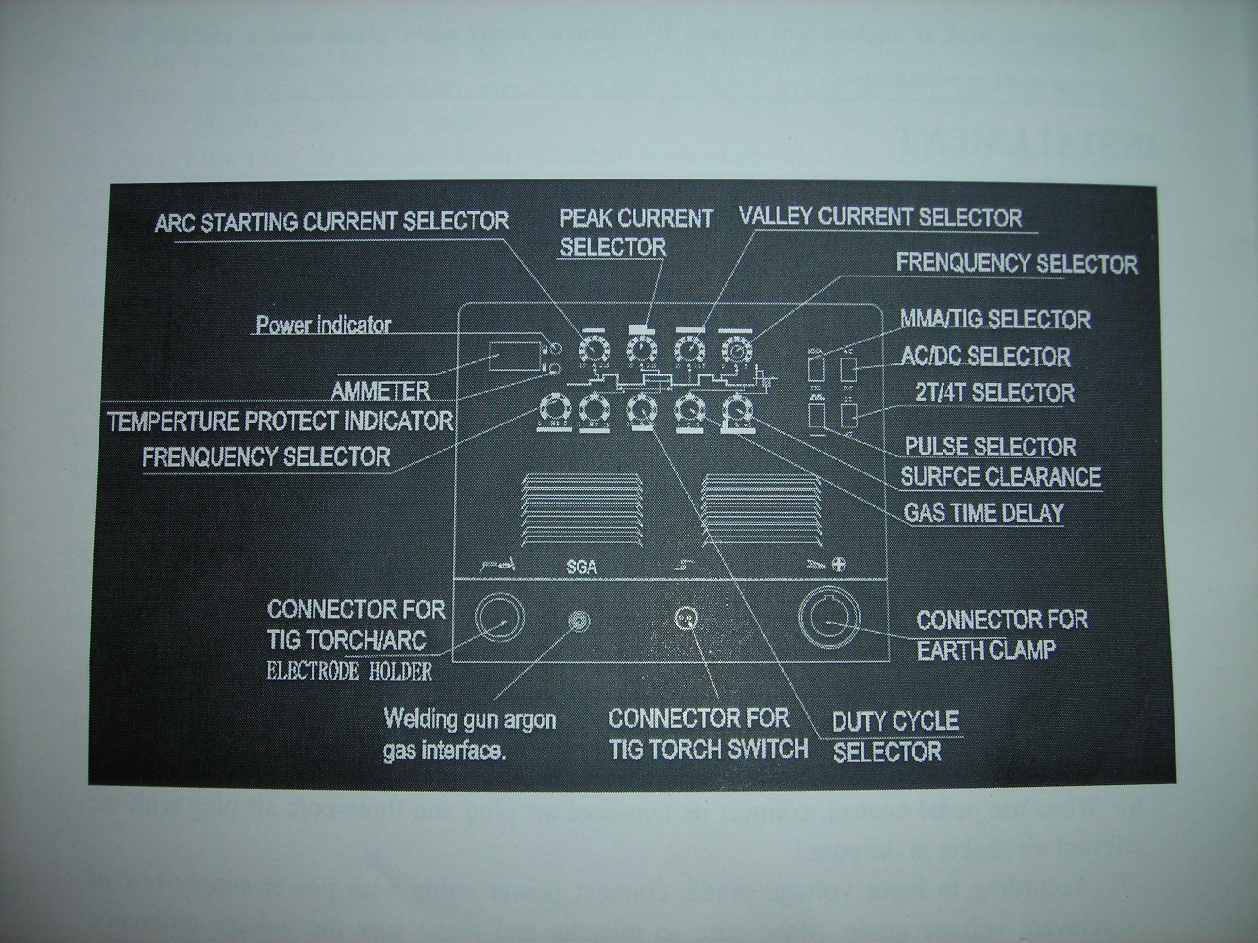
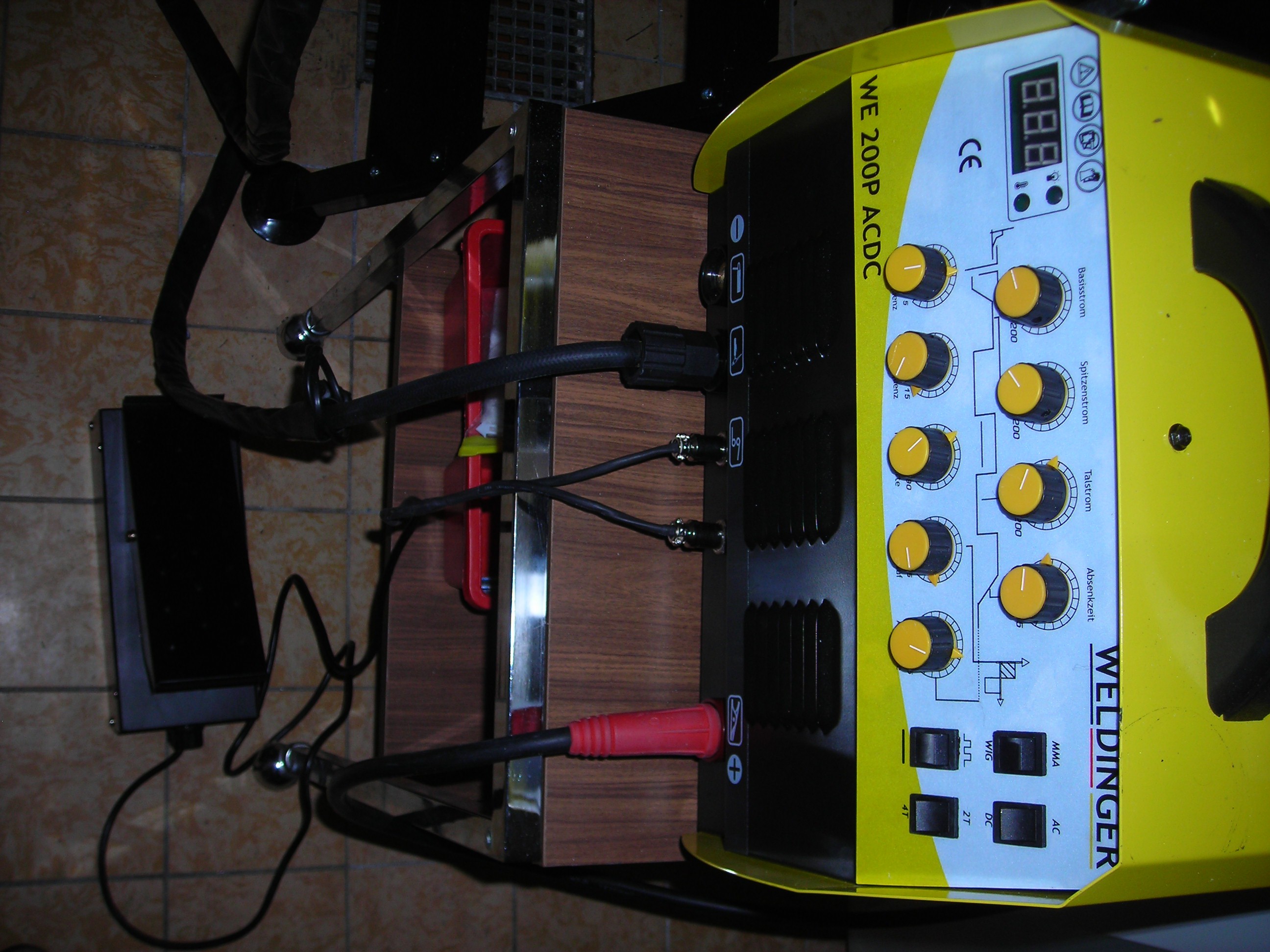
After watching a lot of Youtube videos / tutorials and reading reviews on different welders, I settled for a "semi-analog" machine with DC and AC functionality and most of the control options you see on far more expensive welders. I call it "semi-analog" since the options are controlled via 9 potentiometers and 4 switches on the front panel, so you can not store any settings or profiles (which does not matter for me as a hobbyist). The reviews on Amazon and some german DIY-Forums were also decent, especially concerning reliability and durability in a hobby environment. The german supplier even sells some spare parts. The device also comes with all relevant documentation in german.
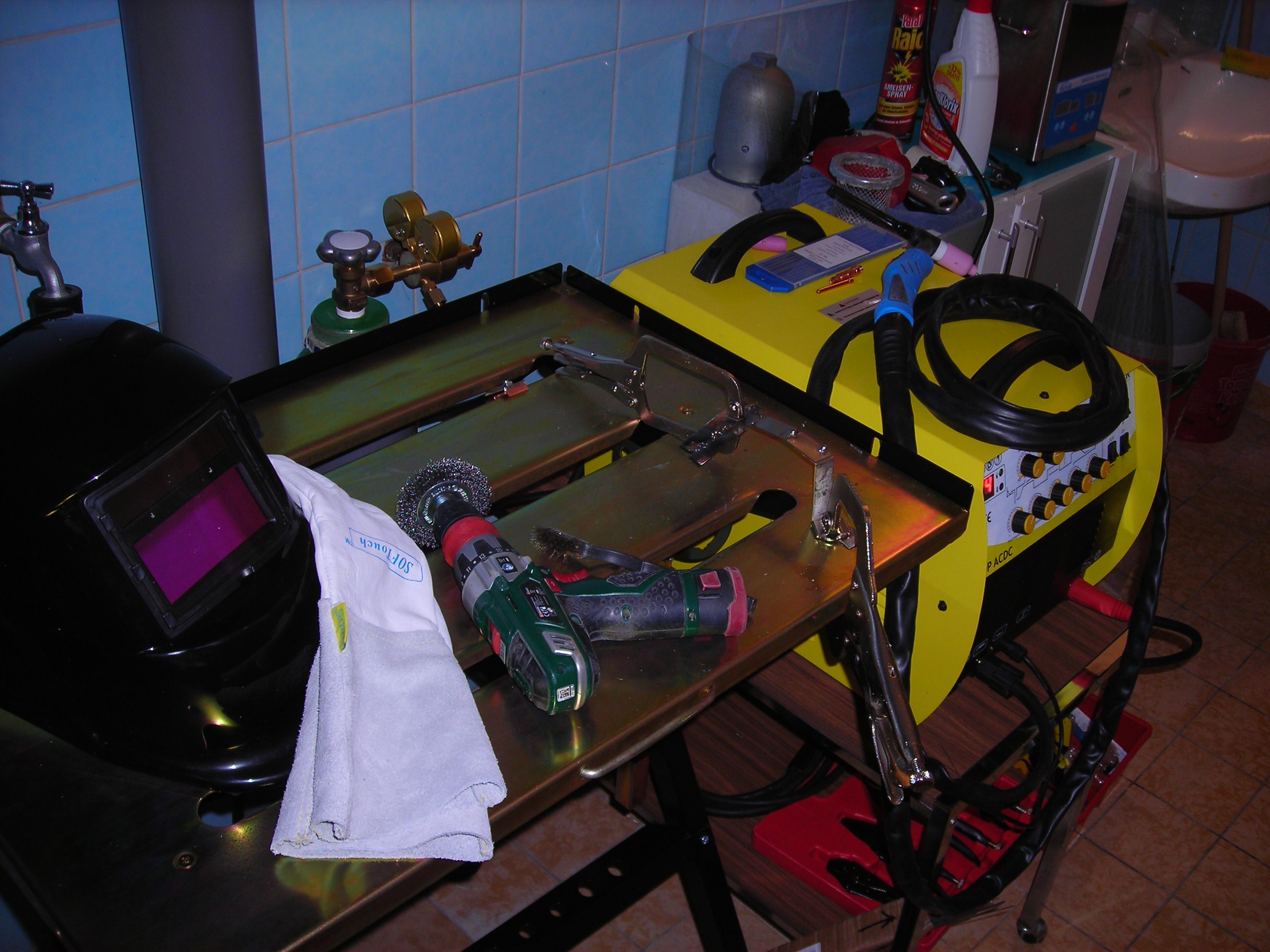
The welder itself cost me about 450€ (End of 2018). It was about 10% cheaper than listed on Amazon when ordered directly from the supplier's webshop. As far as I recall, they claimed that the welder was their own design and was manufactured to their specifications in China.
The machine came with a TIG torch with "button start/stop" option and all necessary cabling + gas hose (except for the welding gas regulator). A foot pedal was not included, but the seller even today lists a pedal especially for this welder in his Webshop. I ordered one right away. The pedal was on back order from China, so I couldn't test it when the welder arrived.
After assembling the welder and doing some test welds in TIG mode, I found the start/stop button functionality a bit problematic, because (especially as a beginner) I never got the welding current / amperage preselection quite right on the first try. There is no way to fiddle with the controls on the front panel when you have to watch your welding area. So I had to stop my test weld, put the torch away, change settings and start over again very often.
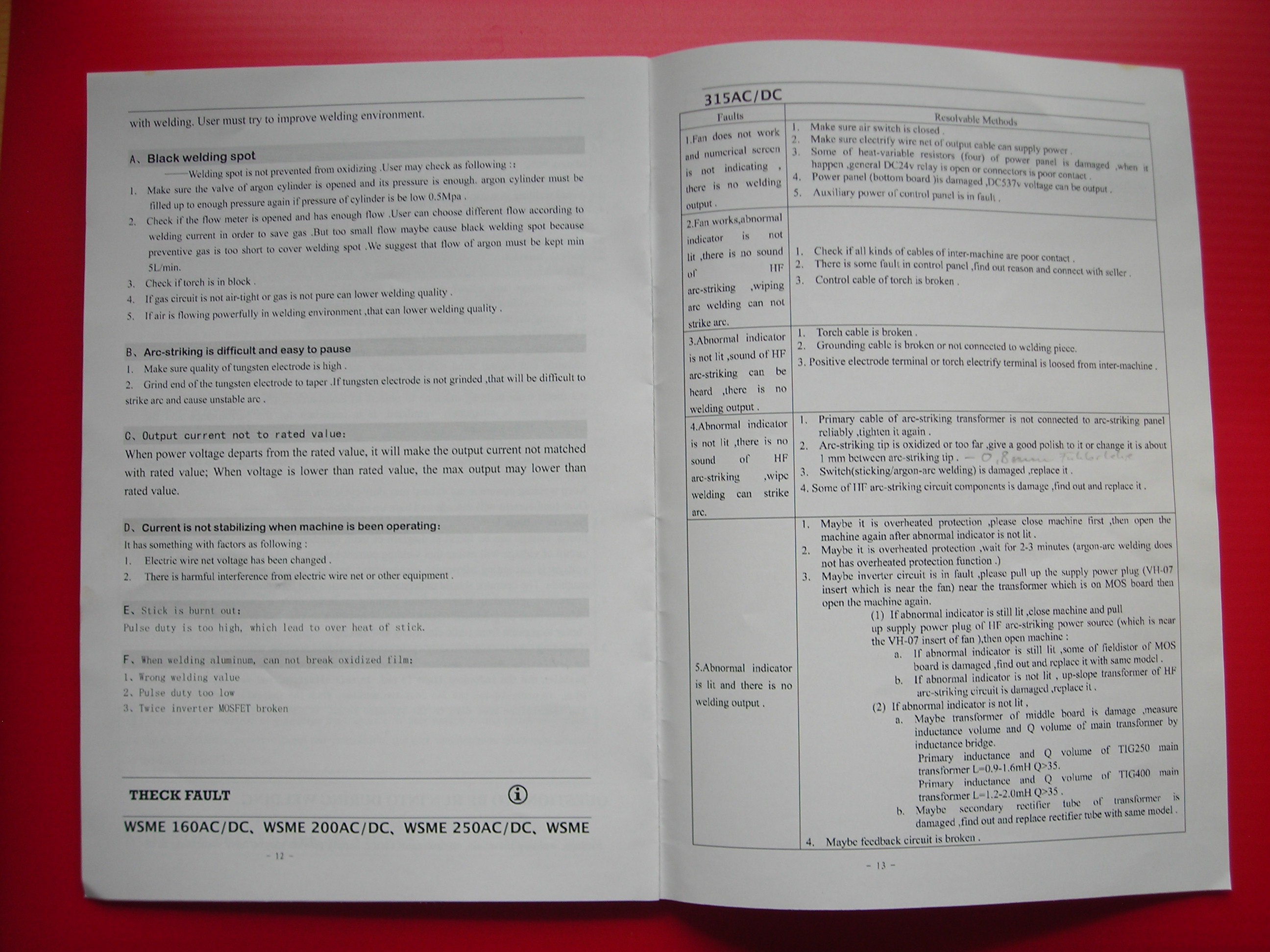
The high frequency arc-start circuit also was not working reliably out of the box (which i know now, after fixing it - at that time I thought I was too stupid to use the welder).
It would sometimes work for 4-5 seconds and then go into "error mode" and not work again until the welder was power cycled. Also, you had to put the tungsten electrode very near to the welding material to get an arc to start (2-3mm) even under best conditions (totally clean material, reliable grounding, high starting current selected).
This resulted in multiple times of "dipping" the tungsten in the weld and having to regrind it. I blamed that mostly on my inexperience and thought the rather frequent electrode contamination was the reason for the "error" states of the welder.
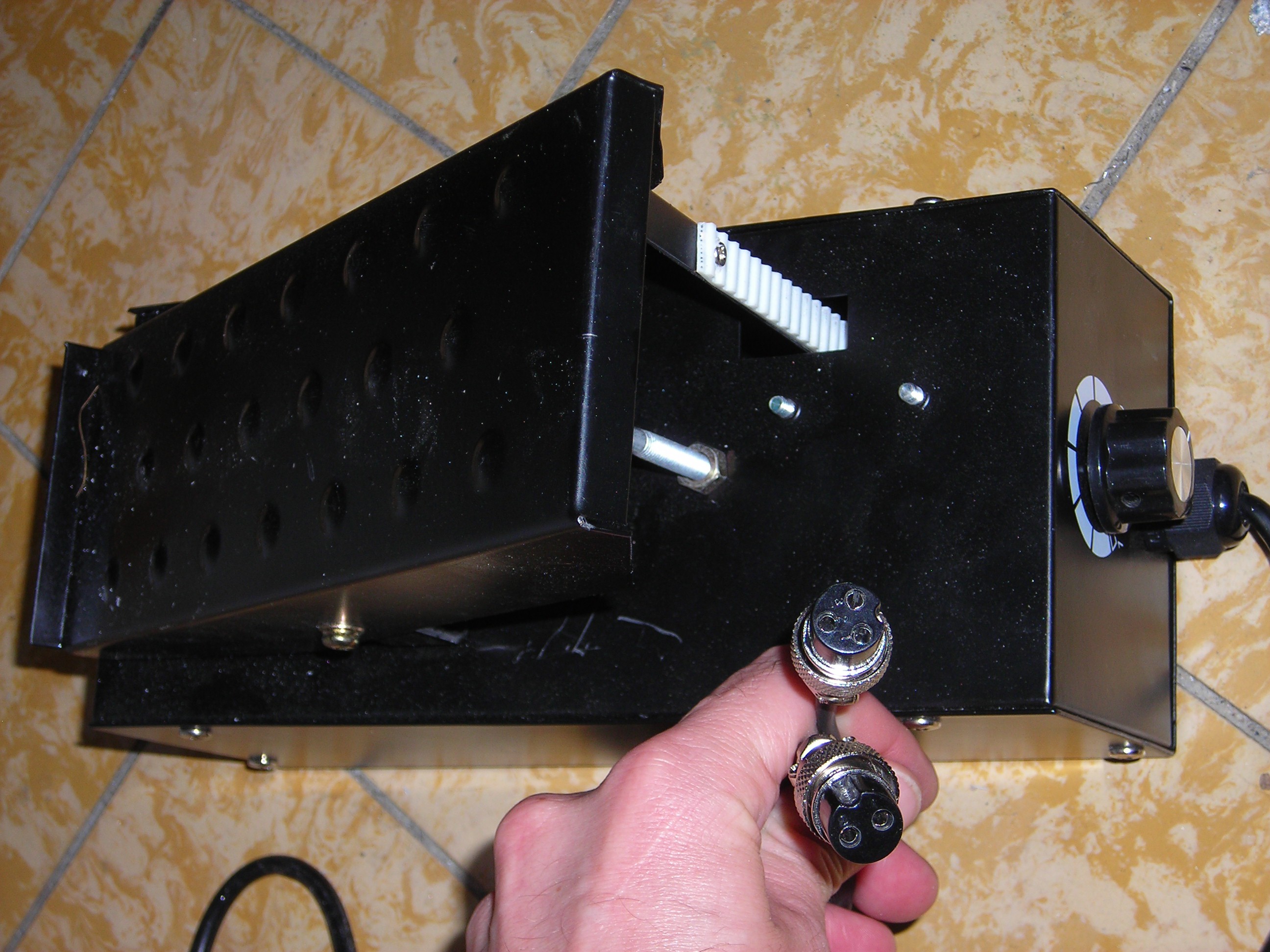
When the foot pedal for the welder finally arrived, I noticed that it had two GX16 connectors, one with 2 and one with 3 pins. My welder only has one 2-pin GX16 on the front panel, this is also used by the button control on the TIG torch. After measuring the connections on the pedal side, I discovered that the 2-pin connector is only for start/stop and the output of the Amperage / Current control via potentiometer is on the separate 3-pin connector.
After checking again with the seller, they told me that the welder only supports start/stop functionality and that there is no provision for amperage control via the pedal (which in my opinion defeats the purpose of selling an additional pedal in the first place). They offer a "better" model with pedal control for >30% more money and even then you have to shell out another 100€ for the pedal itself.
At this point I already owned the welder for more than 2 weeks, so there was no way to send it back for a refund or upgrade because of the missing functionality (Pedal control is to this day falsely advertised as an "option" in the product description and they continue to sell the same pedal for it).
I continued to try out different amperage settings, gas flows, tungsten electrodes, welding wires and test pieces of mild and stainless steel, but with rather unsatisfactory results, even after watching all those Youtube tutorials ;).
"Practice metal" is not cheap to come by where I live (I have no access to a decent junkyard or scrap dealer), so I pretty much stopped my welding exercises when spring came and I had other things to do. (I also didn't start to assemble the welding cart DIY kit I ordered with the welder, because I didn't feel like ruining it right away with my bad welding technique).
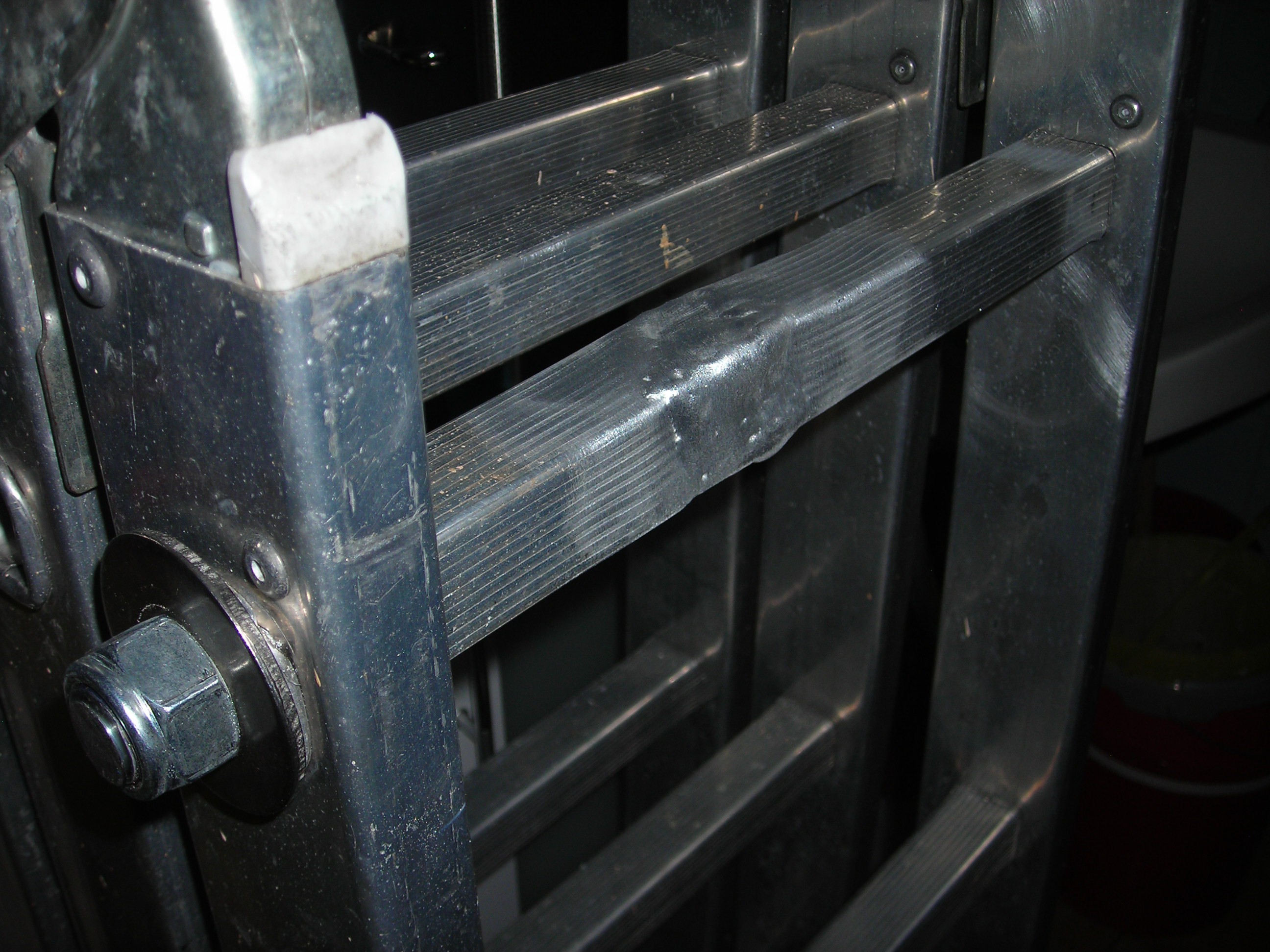
In June 2019 I bent and cracked a step on a rather useful and valuable (to me) aluminium ladder when a tree I was cutting down hit it. The mechanical fix was easily completed by bending the step back into shape and reinforcing it by inserting an M18 threaded rod fixed with appropriate lock nuts and washers, but I decided to see if my welder would be ANY good in AC mode to "reflow" the cracks in the aluminium, even if it was only for cosmetic purposes.
So I switched the welder on again for the first time after 4-5 months. This time it didn't even pretend to work, the arc start function put the welder reliably into error mode after 4-5 seconds of attempted welding every time, even when a stable arc had already formed. This was frustrating. After rummaging through the original packaging while getting ready to send it back for a warranty repair I found an additional user's manual from the "real" chinese manufacturer. It doesn't contain schematics, but at least some halfway usable trouble shooting advices.
Sadly, it also doesn't show any means to connect a foot pedal to the welder.
I decided to open the housing and hopefully fix the defective arc-start myself. This seemed easy enough since there is no warranty sticker and even the german manual recommends to open up and blow out the inside of the welder with an airgun every 4-6 weeks.
Armed with the very accurate troubleshooting advice number 4 from the chinese documentation:
"Abnormal indicator is not lit, there is no sound of HF arc-striking, wipe welding can strike arc" -> "Arc striking tip is oxidized or too far, give a good polish to it or change it is about 1mm between arc-striking tip"
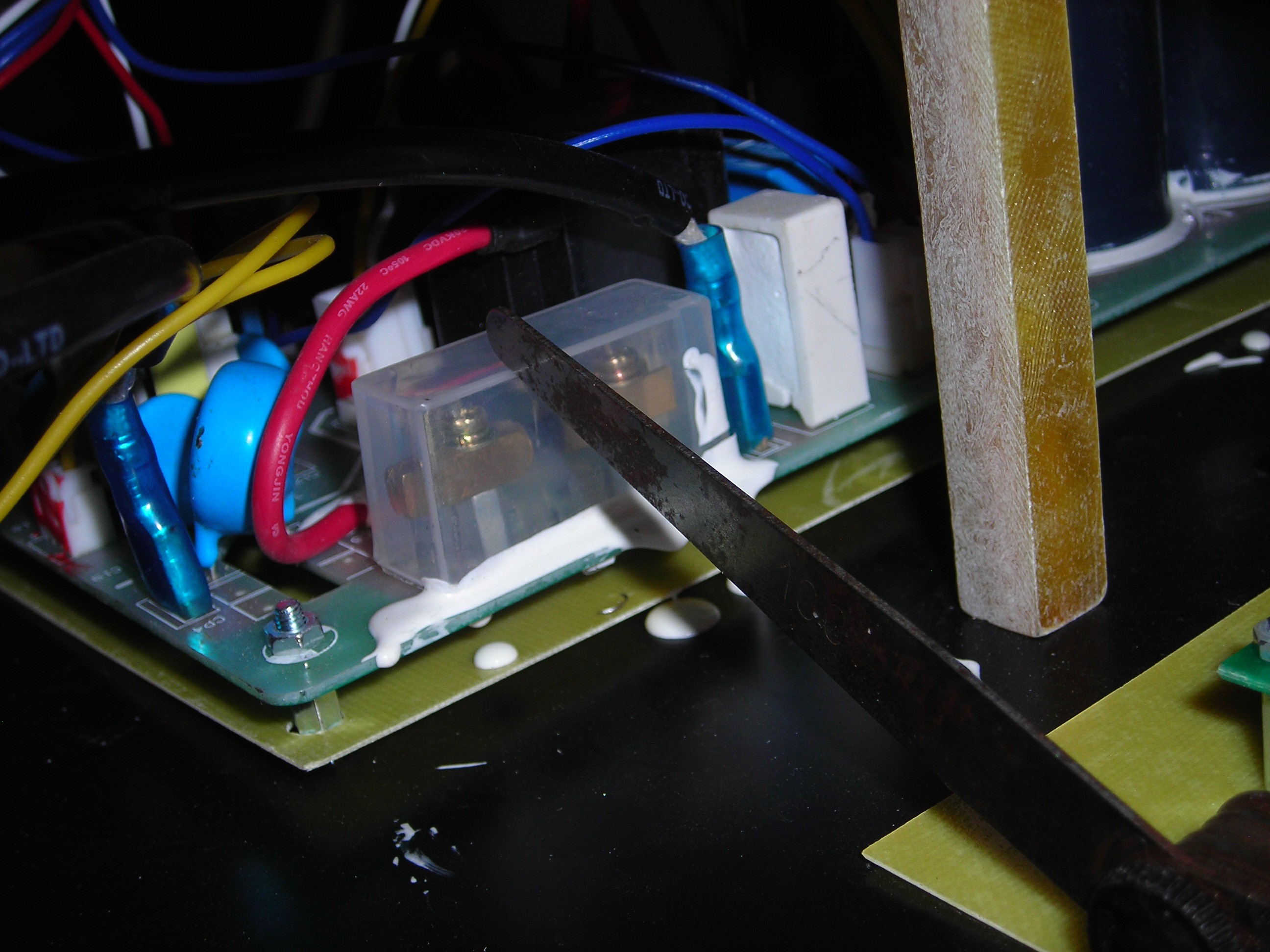
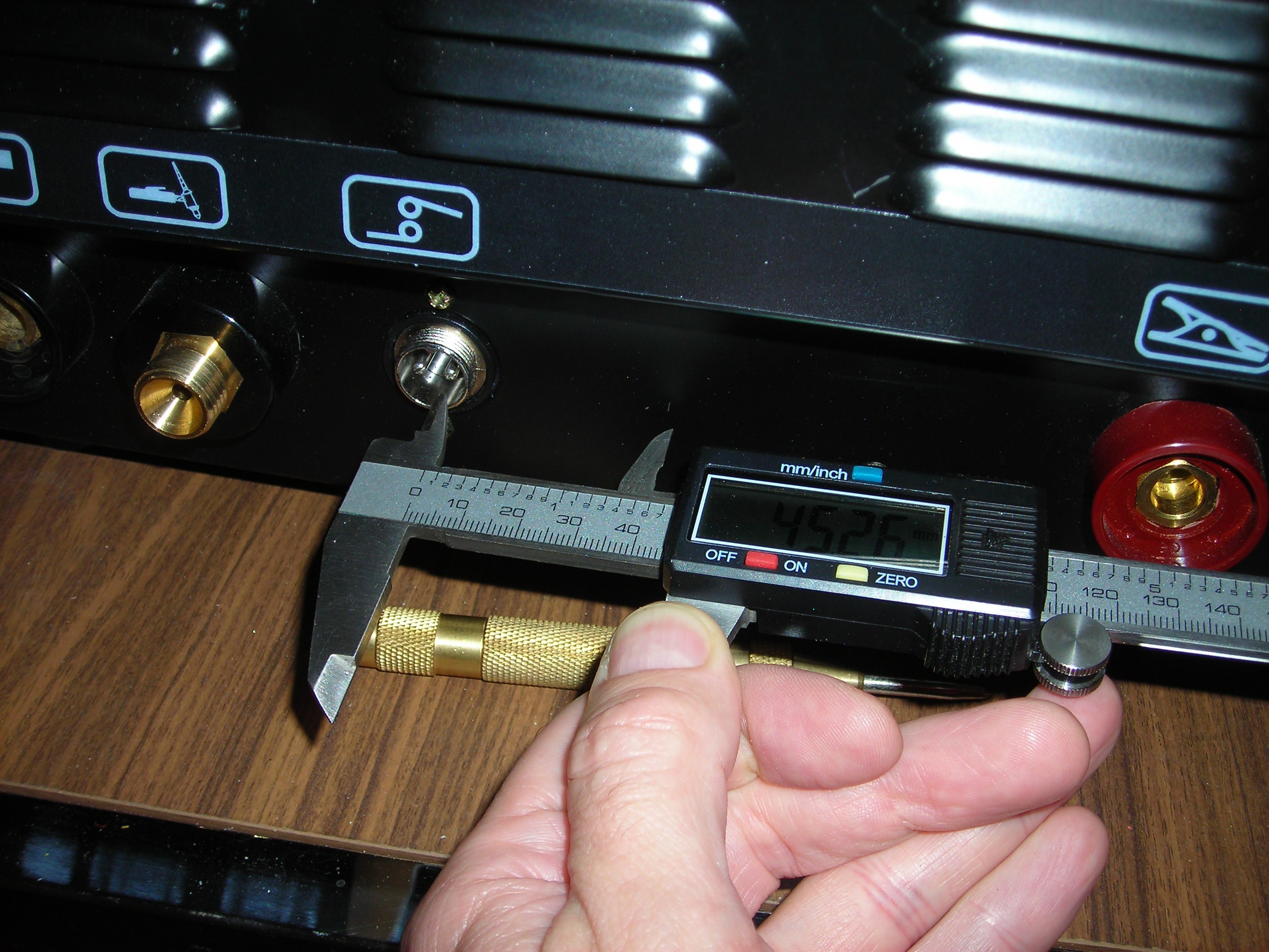
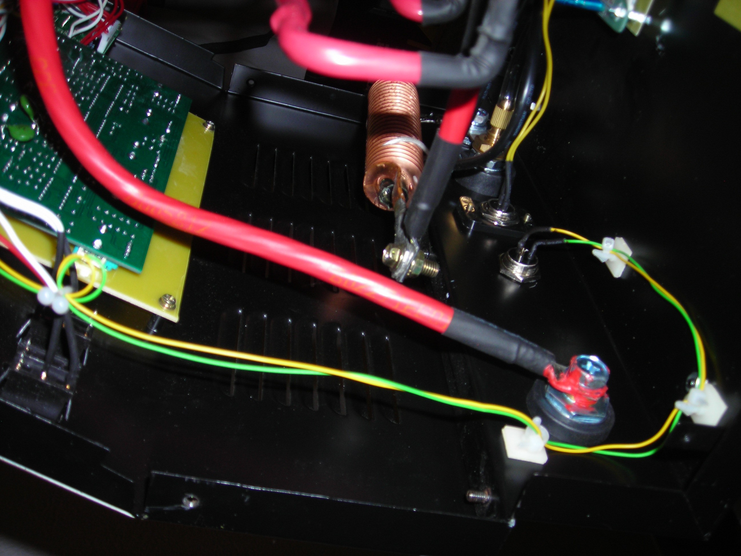
I found a spark gap assembly with a plastic hood on a daughterboard with some inductors and capacitors mounted to the baseplate of the housing. The start/stop connector was also wired to this board, so I assumed that this spark gap was the right one. Both of the electrodes are screwed onto a M3 spacer nut with one philips-screw and no provision against loosening or misalignment / turning of the whole assembly.

The electrodes were noticeably askew - I assume the screws were already loosened while the welder was shipped. Presumably everything had moved a little more in the months since I last used the welder and this now caused the already malfunctioning arc-strike circuit to cut out completely.
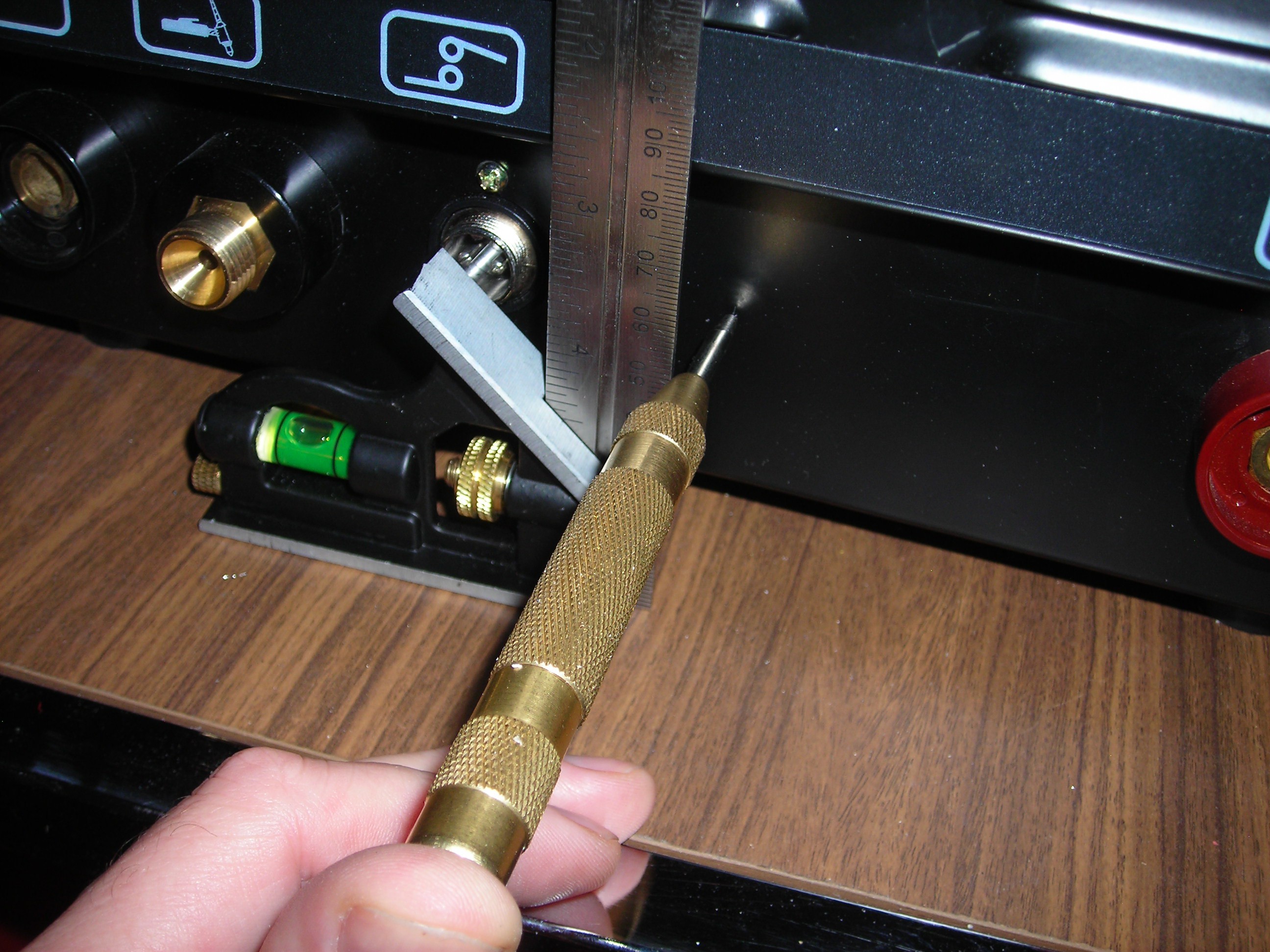
So I took a feeler gauge and an extra long philips screwdriver (because of the rather awkward place the board is mounted) and set the spark gap to the recommended 1 mm.
This showed at least some effect: The spark gap nearly stopped firing altogether when triggered, it only fired maybe once a second (the "buzzing" before was in the range of at least some 200-500 Hz, if not more). But: the welder did not end up in "error mode" after a few seconds again.
After a very short episode of trial and error I came to the conclusion that 0,8 mm seems to be the correct distance for the electrode tips. Since this adjustment the arc-start function runs reliable and I have not encountered any errors since then.
(I only tried the 0,9 and 0,8 mm feeler gauges and refrained from further testing when the function was obviously restored).
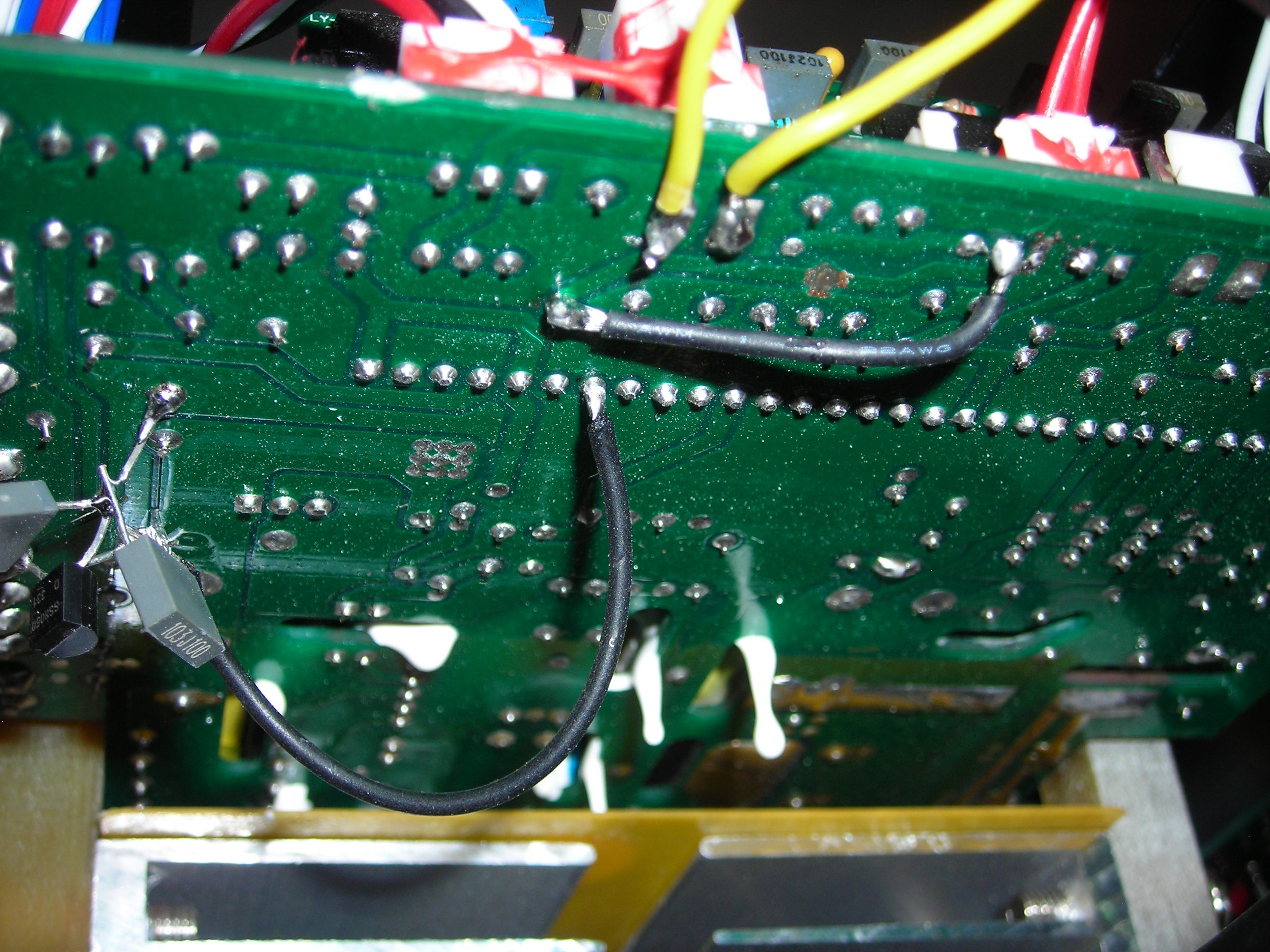
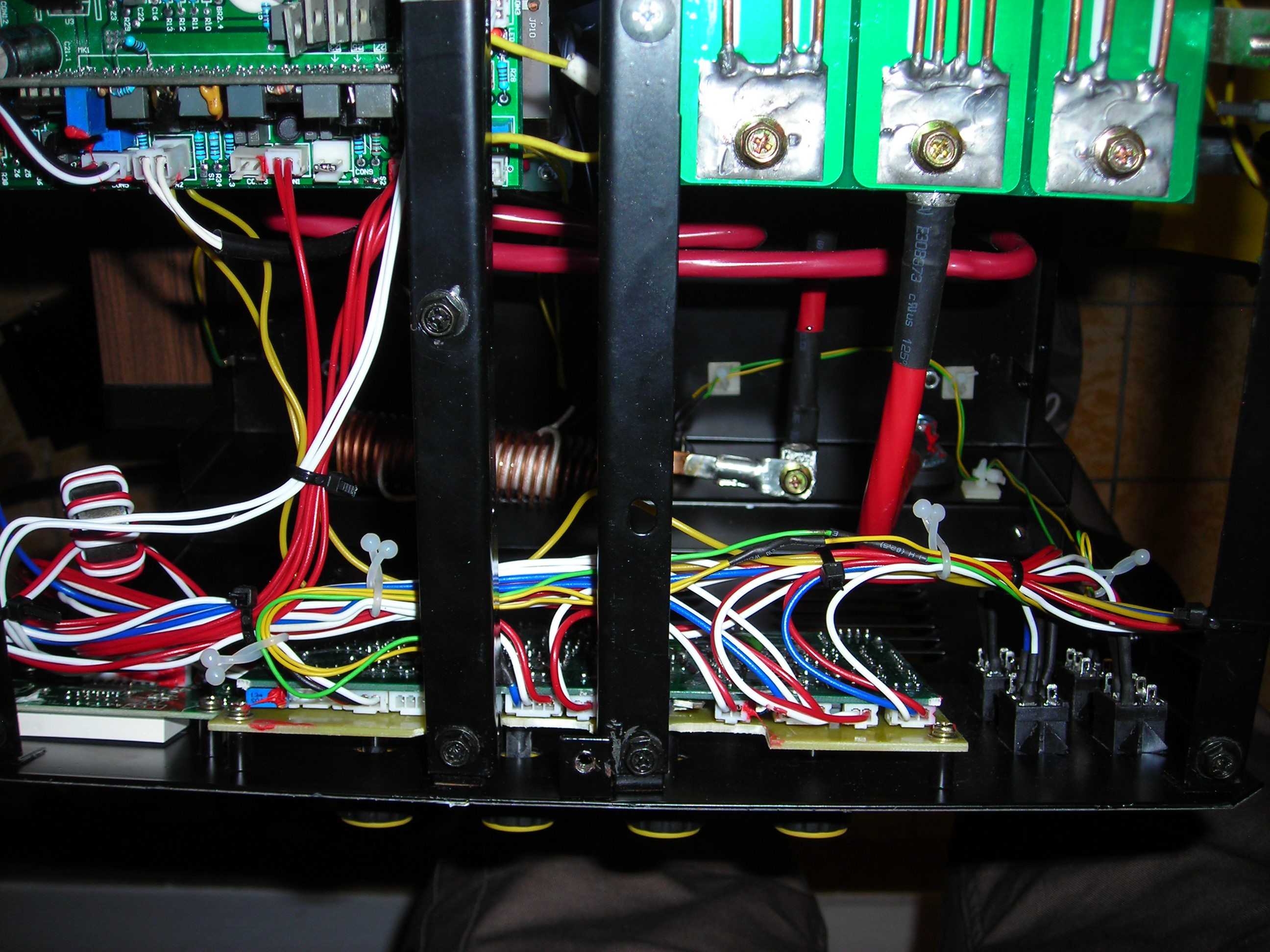
When looking around in the innards of the welder I found some bodge-jobs with at least one deadbugged transistor on the underside of one of the inverter boards, some wires bridging defective traces and some filtering capacitors added to the front panel as an afterthought. So much for a "german designed" welder.
On the front panel board I also found a solder bridge between two traces going to the main amperage (Peak Current) selecting potentiometer near the upper edge of the board.
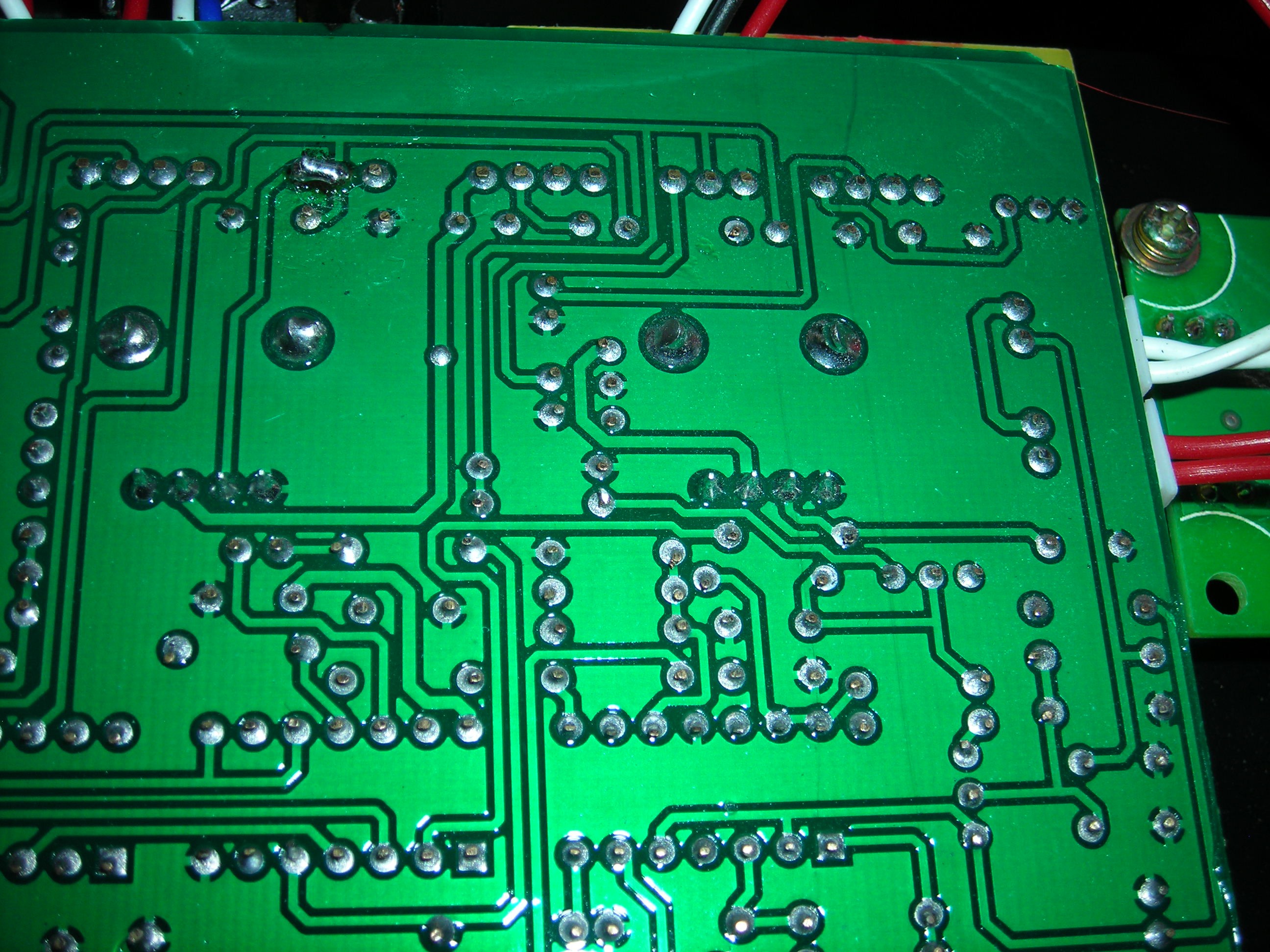
The solder bridge was between the pins of an unused 3-pin Molex socket on the upper edge of the board. This connector (and another unused 4-pin socket directly to the left) were labeled "REM".
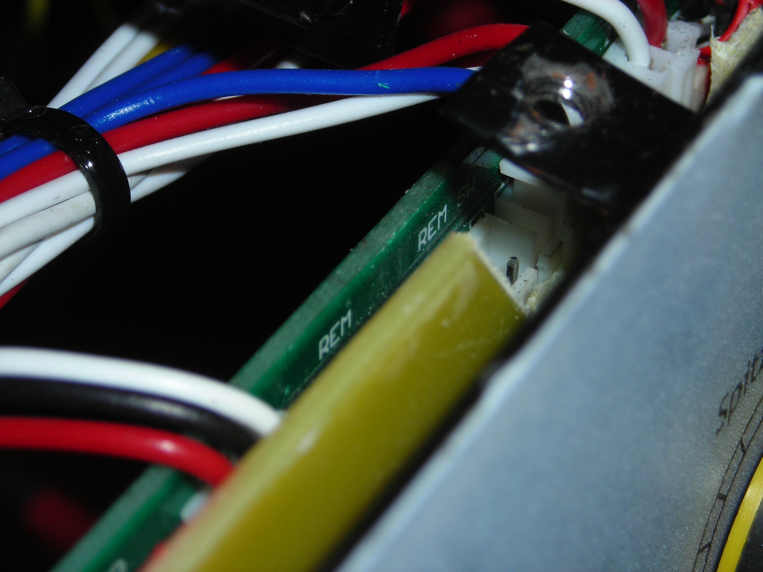
Obviously, there was at least a possibility (perhaps with another daughterboard) to connect a remote / foot pedal to this kind of front panel.
I wondered if the solder bridge was intentional, so I removed it. Without the solder bridge, the "Peak Current" potentiometer did not work any more and the value was stuck at minimum (20A).
I measured the value of the front panel potentiometers "in situ" and at least the ones I could easily get to seemed to have a value of about 15k. They are connected like standard "volume control"-potentiometers: the higher the selected value, the lower the resistance.
The foot pedal (which has 2 potentiometers in serial connection) measured approximately the same resistance. If the multimeter is connected between pins 2 + 3 of the GX16-connector the resistance goes up when depressing the pedal, between pins 1 + 2 the resistance goes down, which is the desired signal.
The 2 formerly bridged pins of the 3-pin "REM" socket (pins 2 and 3, counting from left to right) on the front panel seemed to connect in series to the Peak Current potentiometer, the other one (pin 1) seems to connect to the ground plane of the board.
I wondered if I could simply put the pedal in series to the Peak Current potentiometer and wired up a corresponding 3-pin Molex connector, plugged it in and connected it to the pins 2 + 3 of the pedal connector. This worked insofar as that pressing down on the pedal now did change the amperage, but only a very little amount (5-10% of the preselected amperage).
This was not the effect I was looking for. To have a significant influence on the selected Amperage the potentiometers in the pedal would have to be connected in parallel to the "Peak Current" potentiometer.
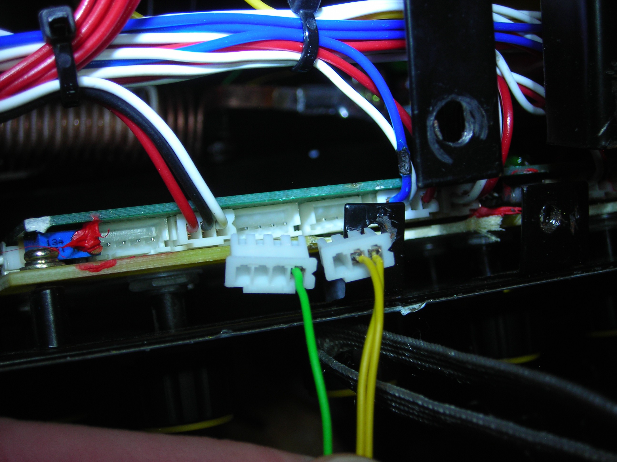
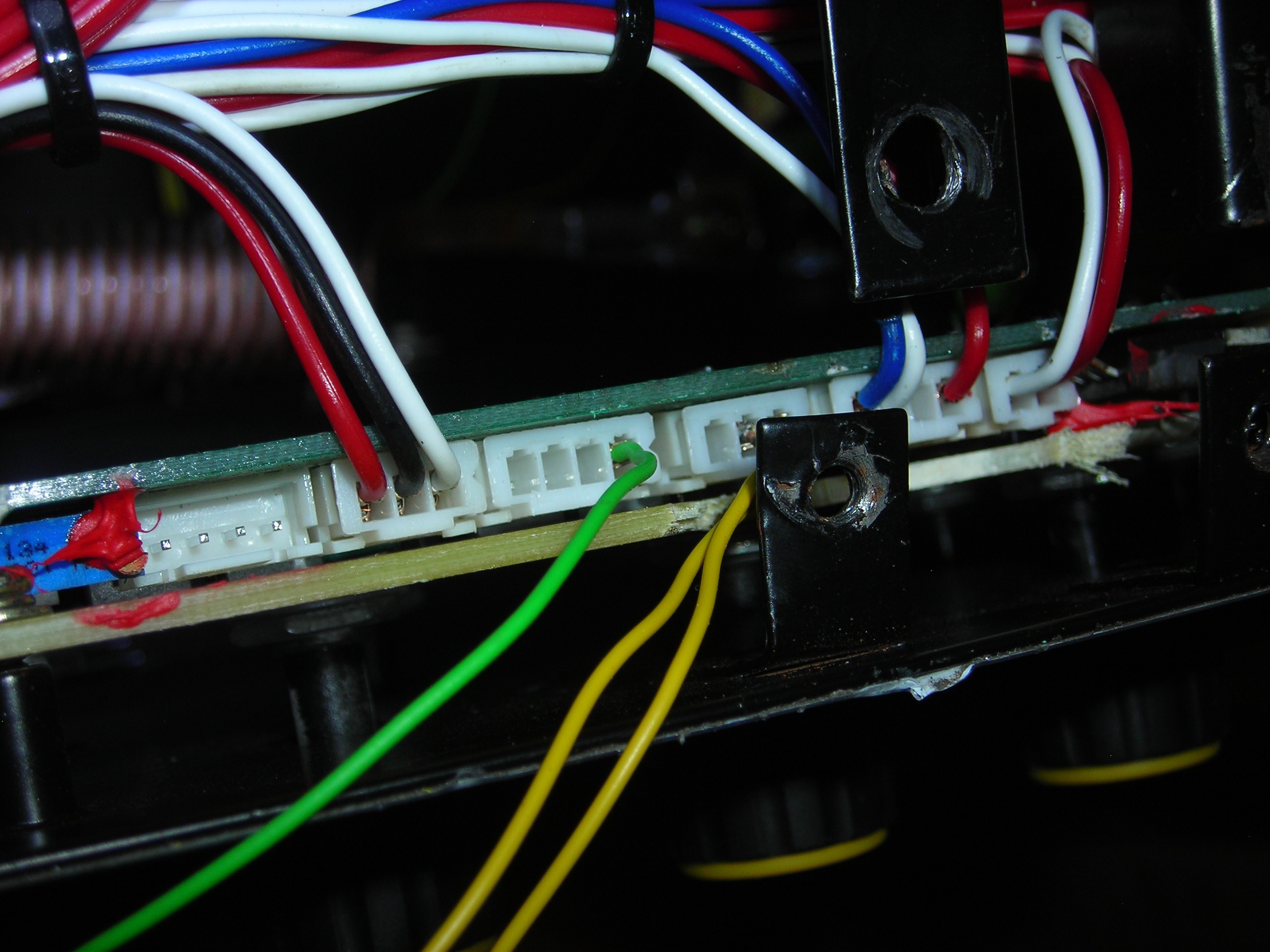
So I took a look at the 4-pin Molex socket also labeled "REM" to the left of the first one. On this one, the two pins to the right (pin 3+4) looked promising (as far as the traces on the bottom of the board were visible), so I went ahead and prepared another 4-pin Molex connector with pin 3+4 wired up.
It turned out that only the rightmost pin/cable (pin 4) on this socket is of interest, because it provides the desired parallel connection to the "Peak Current" potentiometer. The traces on the board already hinted at this, and I verified it by measuring the variable resistance of the "Peak Current" potentiometer between this pin and the originally bridged pins (pins 2 and 3) of the neighboring 3-pin Molex.
So I finally put the solder bridge between pin 2+3 of the 3-pin Molex back (to be sure everything works later on even if the additional connectors should at some point be removed) and connected pin 1 and 2 of the pedal's 3-pin GX16-Plug between pin 4 of the 4-pin "REM" Molex and pin 2/3 of the 3-pin "REM" Molex (it doesn't matter to which one as long as the solder bridge is in place - I left both of the cables in the connector because it is hard to get to and easier to pull out when the force is distributed on 2 wires instead of a single one).

Wiring instructions
GX16 Pin 1 (yellow) -> 3 pin-Molex "REM" pin 2+3
GX16 Pin 2 (green) -> 4 pin-Molex "REM" pin 4
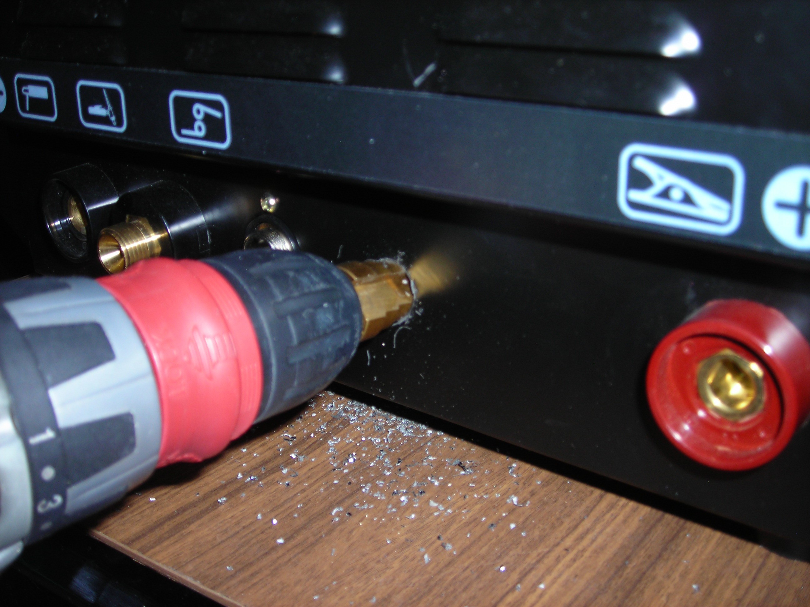
After verifying that everything works I ordered a GX16-Socket and installed it roughly in the position it should be on the front panel (judging from the position of the other cnnectors). I routed the wires on the right side of the front panel to avoid the HF starter coil in case of interference (there was none, even when everything was connected with alligator clipped test leads dangling about the housing).
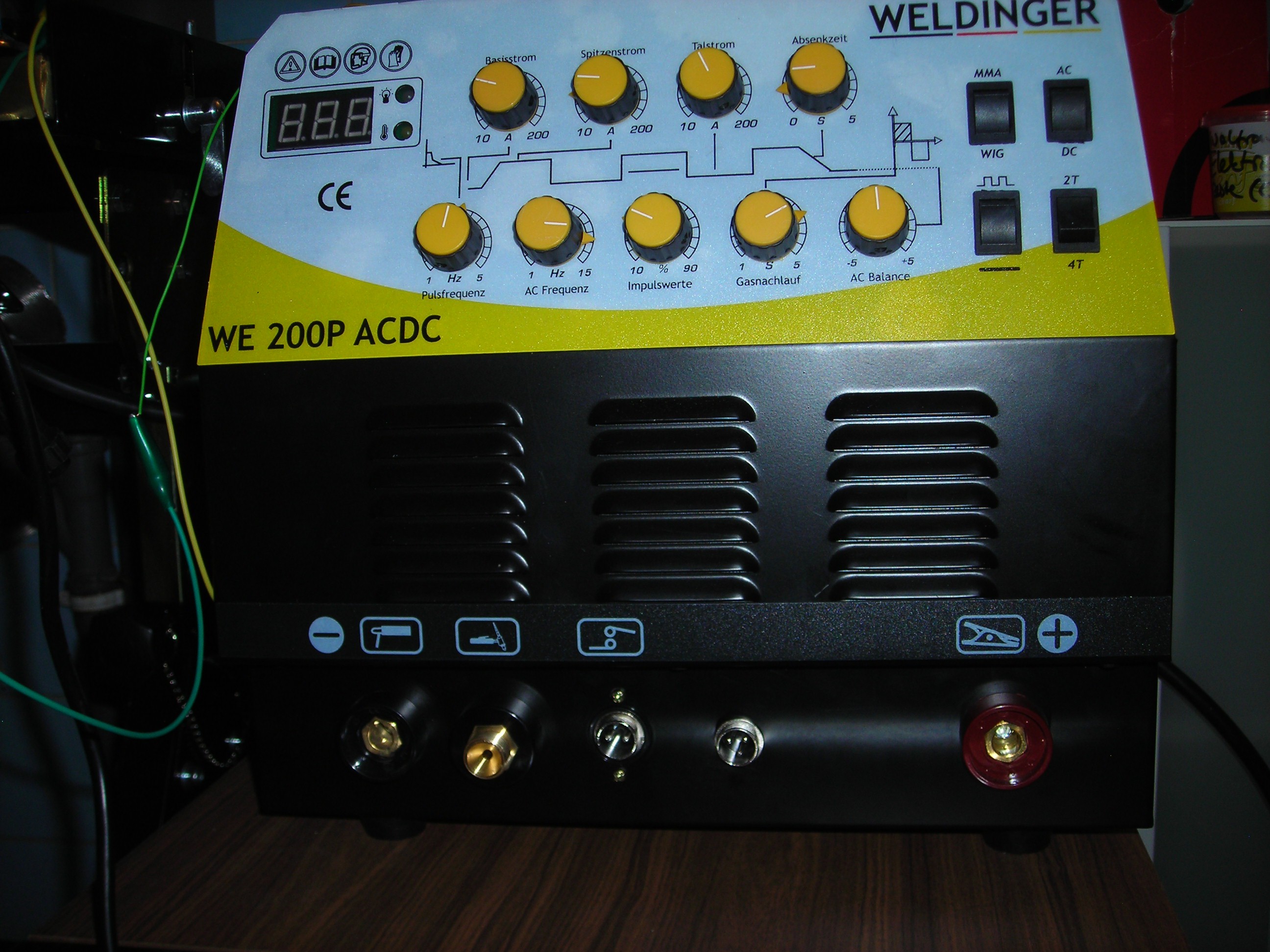
So now I have a working TIG foot pedal and a reliable arc-start function, which improved my nearly non-existent "welding skills" considerably, because it is now finally possible to vary the amperage/current transferred to the welding material while welding. Also, I tend to contaminate the tungsten much less often because the arc now starts reliably on manageable distances.
I even was able to weld up the cracked step of my aluminium ladder. Doesn't look pretty, but the cracks are gone ;).
P.S. I don't know if it is really the correct way to have the potentiometer(s) in the pedal in parallel to the "Peak Current" preselection potentiometer on the welder front panel or if you would normally employ some kind of switching between internal and external potentiometers (which could / would perhaps be done with a daughterboard and the extra pins on both of the "REM" connectors).
As my pedal is wired now, I sometimes have to change both the "Peak Current" preselector on the welder and the potentiometer on the front of the pedal to reach certain Current ranges.
But - the nice (for me) thing is this: because the resistors / potentiometers are wired in parallel I also can change the sensitivity or "range" of the pedal.
When I leave the potentiometer on the pedal (marked with a generic scale between "1" and "10") below "5" I can add between 10 and 40% more amperage when using the full travel of the pedal.
If I turn it up between "6" and "10", the range of the pedal gets much wider and I can apply full amperage (200A) with a "kickdown" even when I only had some 40A on preselection before.
I find this especially useful when trying to weld bigger parts or joining two parts with a lot more heatsinking capacity than initially expected.
P.P.S. If you do a Google Picture search for the original chinese product ("WSME 200 TIG") you find the same welder with totally different housing designs from a lot of resellers worldwide. The front panel elements (9 potentiometers, 4 switches) are the same on all these welders, so it's relatively safe to assume the innards are the same, too.
Most of the "new" pictures (as of July 2019) seem to obviously include the 3-pin GX16-socket for the pedal nowadays, so you can buy this welder with pedal control out of the box (you just have to look).
The "Weldinger" version is still sold without the connector for the pedal. I assume the only thing "made to german specifications" is the somewhat different sheet metal housing and the german inscripted front plate....
Discussions
Become a Hackaday.io Member
Create an account to leave a comment. Already have an account? Log In.
you have no idea how much you helped me man. Thank you very much :)
Are you sure? yes | no
What a masterclass of DIY dude! Congratulations and thank you so much for share your knowledge.
Are you sure? yes | no
Thanks so much for posting this! I have just bought this welder and was considering buying the foot pedal. But I guess I will just mod it the way you have, and build my own pedal instead. Lots of really good info in your post - thanks again.
Are you sure? yes | no