 Brandon Reinhart
Last night I built and tested registers A & B. This is an easy place to start as these registers are only two chips each.
One of my goals for this project is to avoid using Ben Eater's schematics. When I built my first computer, I followed his videos and made sure I understood each step - but knowledge can fade without regular use. By forcing myself to make my own schematics and do my own planning, I can find the places where my understanding is weak. I'll make more mistakes and that will force me to improve.
The brain of each register is a 74hc574. The 574 is the mil-spec version of the 374 octal d-type flip-flop; positive edge-trigger; 3-state. I ordered the 574's from Digikey on accident. The 374 would have been just fine.
Since this is a 3-state IC, it can provide outputs as high, low, or high-impedance. I think of that third state as invisible. When it's in that state, it's like those output pins aren't there. This would let me tie the inputs and outputs of the 574 directly to the bus, but I can't in this case because I also need these registers to be tied to the ALU. The ALU wants the A and B registers to always be on, but the bus only wants to see them when the correct control flags are set.
To solve this, I'm using a 74hc245 octal bus transceiver; 3-state. This chip gives us a directional control to determine if we're reading data from the bus or writing data to the bus. It also gives us a high-impedance setting so we can effectively disconnect the register from the bus when it's not active.
The d-flip-flop's output will always be on and it will drive the 245 and the ALU. The control logic for the register will set the appropriate state on the 245.
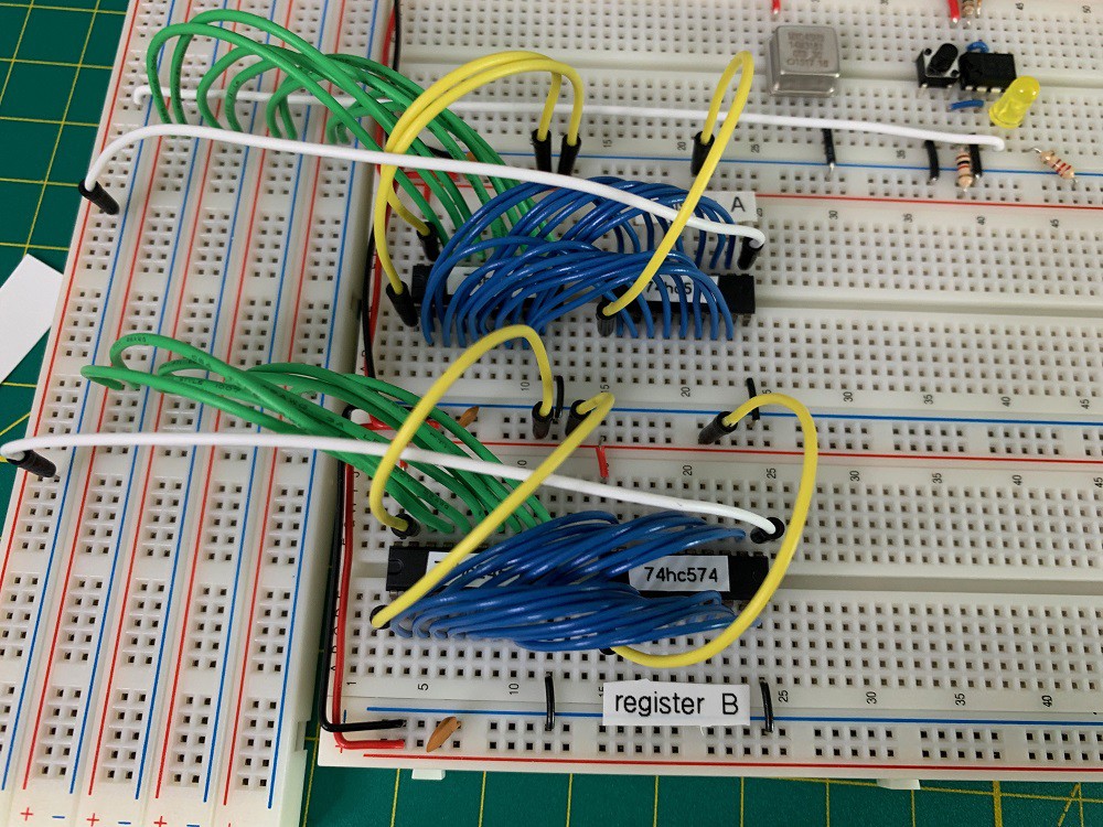
We can wire both the output and input of the d-flip-flop to one side of the transceiver (blue wires). The other side of the transceiver connects to the bus (green wires).
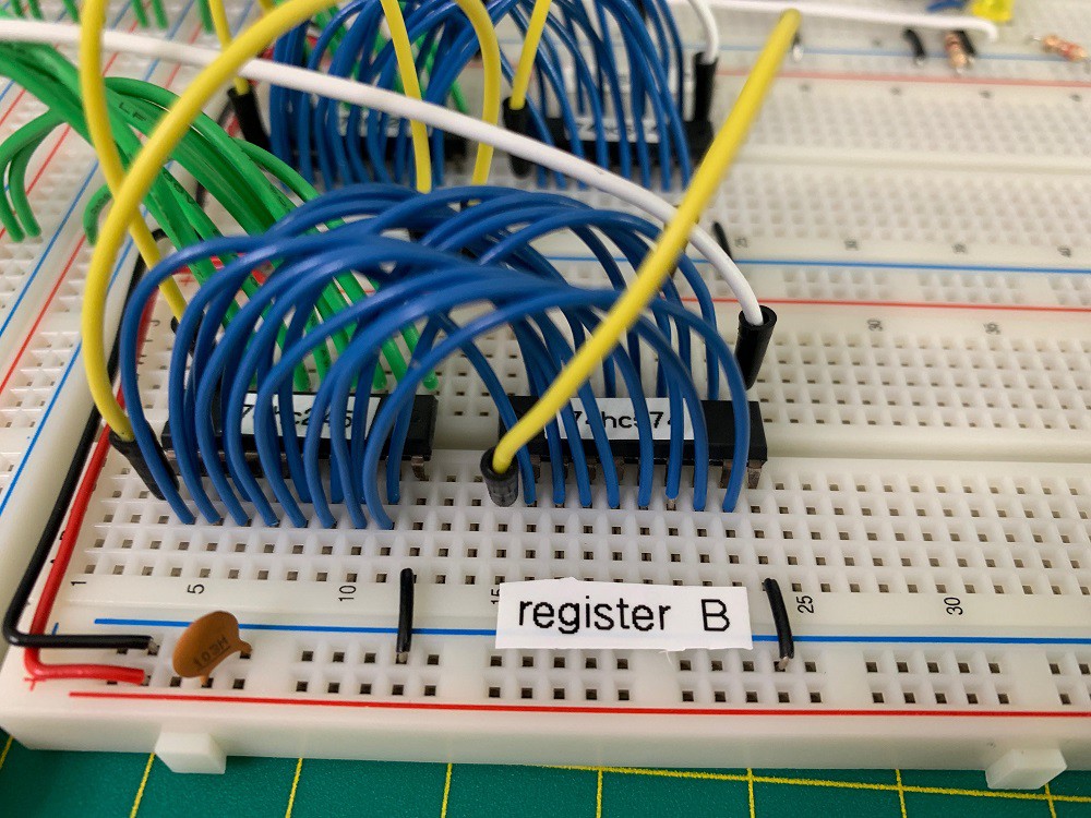
The yellow wires are control bits. From left to right: transceiver direction, transceiver enable, and register enable. The white wire is the clock. The yellow and white jumpers are temporary. Those lines will be connected to the control bus later.
When I built my first breadboard computer I duplicated Ben Eater's wiring style and layout. All of the lines were cut short and flat to the board. This time I'm favoring lines that arc above the board in more direct paths. My hope is this ends up cleaner, with connections that are easier to trace and fewer kinks because of less need to crimp right angles. I got this idea looking at the Vulcan-74 (https://www.atomiczombie.com/vulcan-74/). We'll see if this scales.
I ended the night by wiring the registers to a temporary bus (green wires) and testing the read and write functions.
Discussions
Become a Hackaday.io Member
Create an account to leave a comment. Already have an account? Log In.