 Brandon Reinhart
Tonight I built the program counter (PC) register for the computer. I also blinded myself with some FREAKISHLY bright green LEDs that I hooked up for debugging. Holy crap, I can still see the after images even now. Yeah, so, I'll be putting bigger resistors on those suckers tomorrow.
The program counter is composed of two banks of 4-bits, giving it an 8-bit capacity. My previous breadboard computer could only count to F, this one can count to FF... progress!
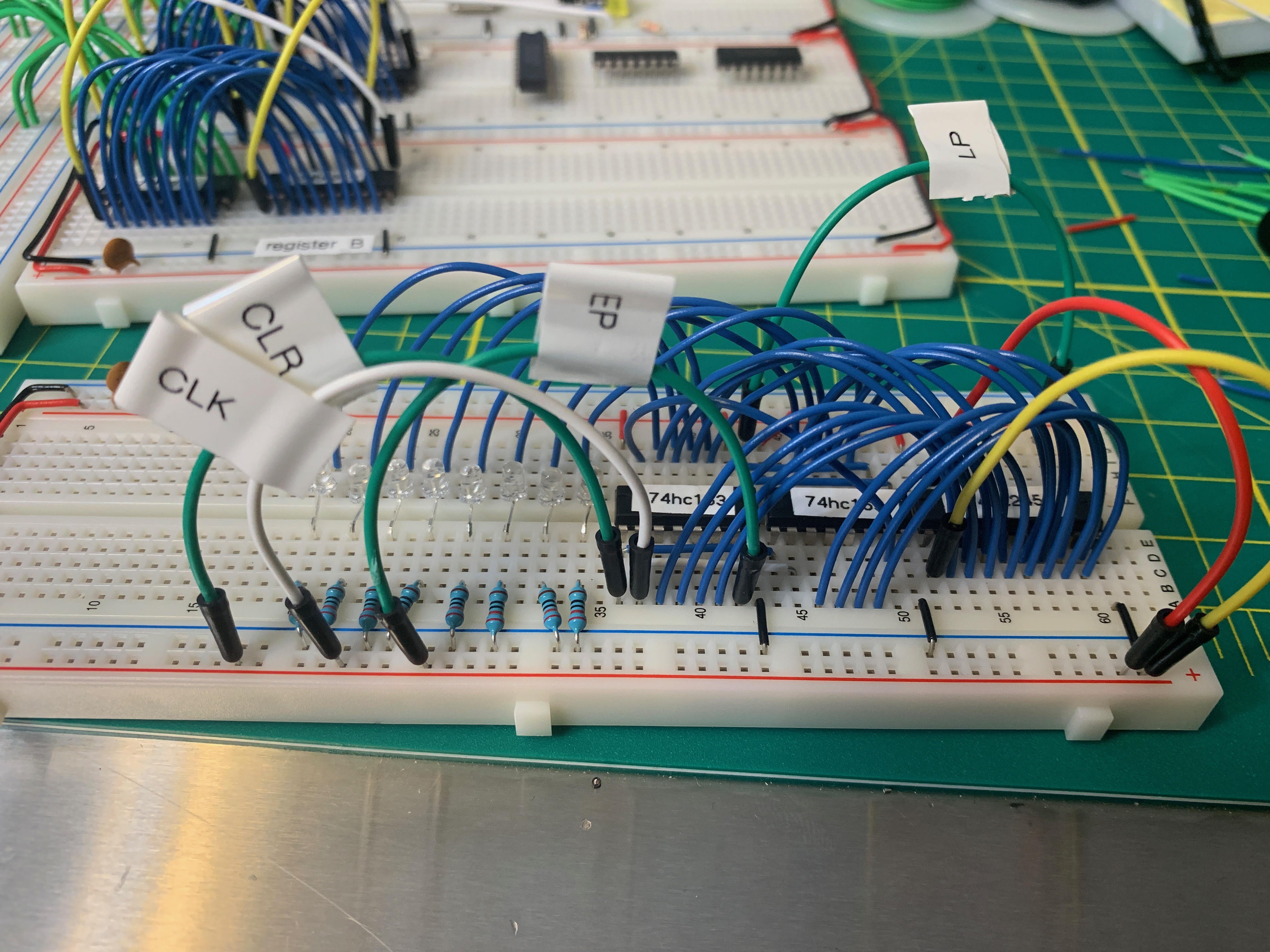
There are three ICs that compose this module, configured similarly to the registers A and B. There are two 74hc163 presettable synchronous 4-bit binary counters; synchronous reset and one of the 74hc245 octal bus transceiver; 3-state. Since the binary counters don't have 3-state output, we can't wire them directly to the bus. The input and output pins of the counters are wired to the A side of the transceiver. The B side will be connected to the bus. The transceiver can be set to inload from or exload to the bus or be in the high impedance (invisible) state which effectively disconnects the module from the bus.
The wiring of the counters is straightforward. I've labeled the various control leads so I don't forget what does what. It's easy to read a datasheet, get everything working, and then five minutes later have no idea which pin does what operation. I've labeled these using the terms that Malvino uses in his discussion of the SAP-2.
- LP - Load program counter. Active low. Halts counting and loads a word from the bus into the counter.
- EP - Enable program counter. Active high. When active, the counter will count.
- CLR - Clear. Active low. When active, the counters will zero out on the next clock.
- CLK - Clock. The counter counts, loads, or resets on the rising edge of the clock.
The 74hc163 has a carry out bit called the "terminal count output" which is wired to the enable of the second set of 4 bits. This will cause the high order bits to count when the low bits have a carry. In the implementation below, the left chip handles the low 4 bits and the right chip is the high 4 bits.
BLINDED BY SCIENCE
I don't really want to have blinkenlights all over this computer. I got over that with my first breadboard computer and my hope is that this one operates at a high enough speed that the lights wouldn't offer any useful information or entertainment. I did wire up an array of tiny LEDs to the counter to test it out.
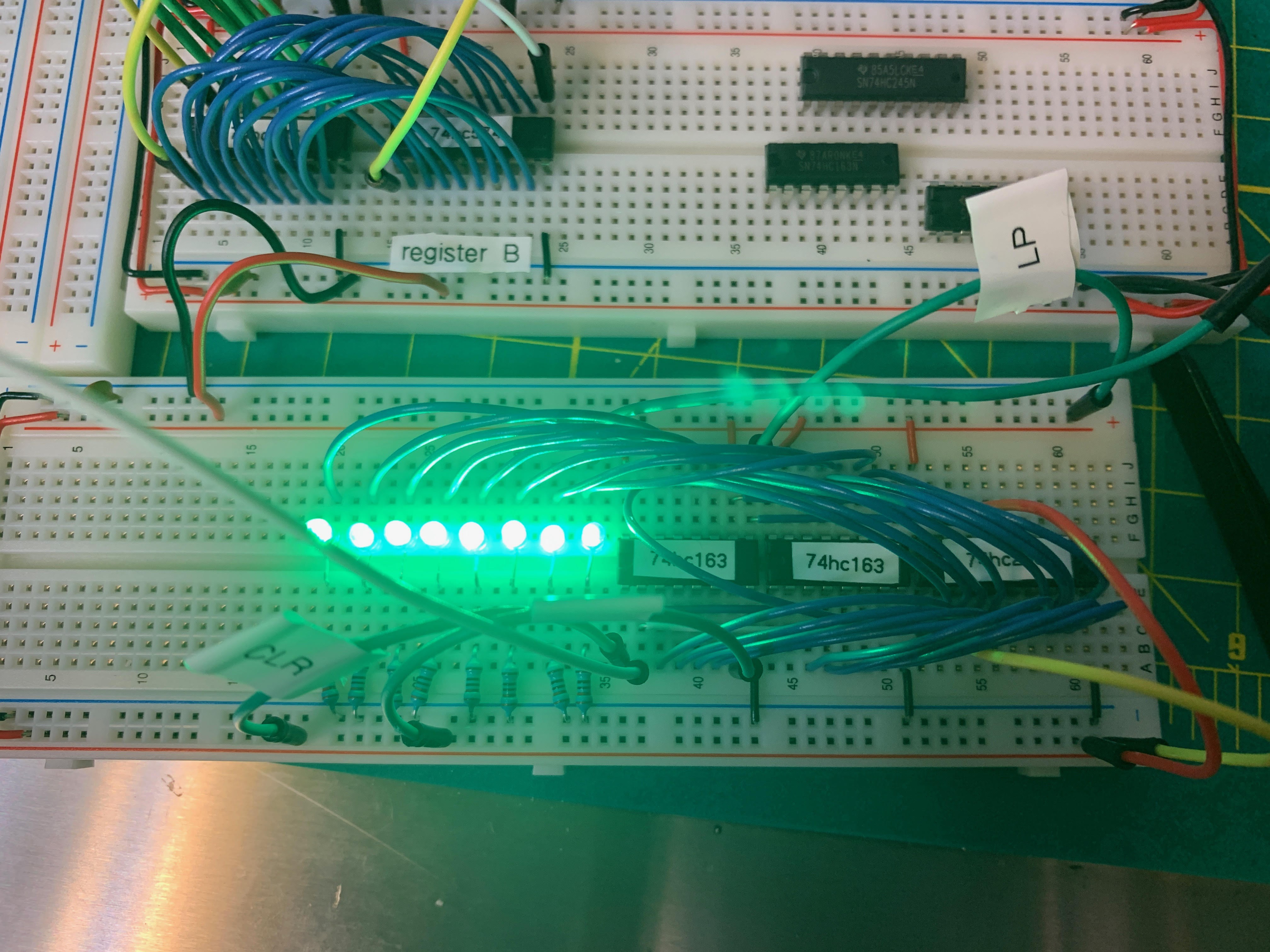
This isn't very smart on my part because i have light sensitive eyes and a nasty case of visual snow. Acute retinal damage aside, when I hooked up the CLK signal to a mono-stable switch I was able to click through all 256 states. The LEDs are wired up backwards, but they work.
After that test, I plugged a 14.31818 Mhz clock crystal into the CLK signal and let her rip. That's why all the lights are on in the picture above. It's blinking really, really fast.
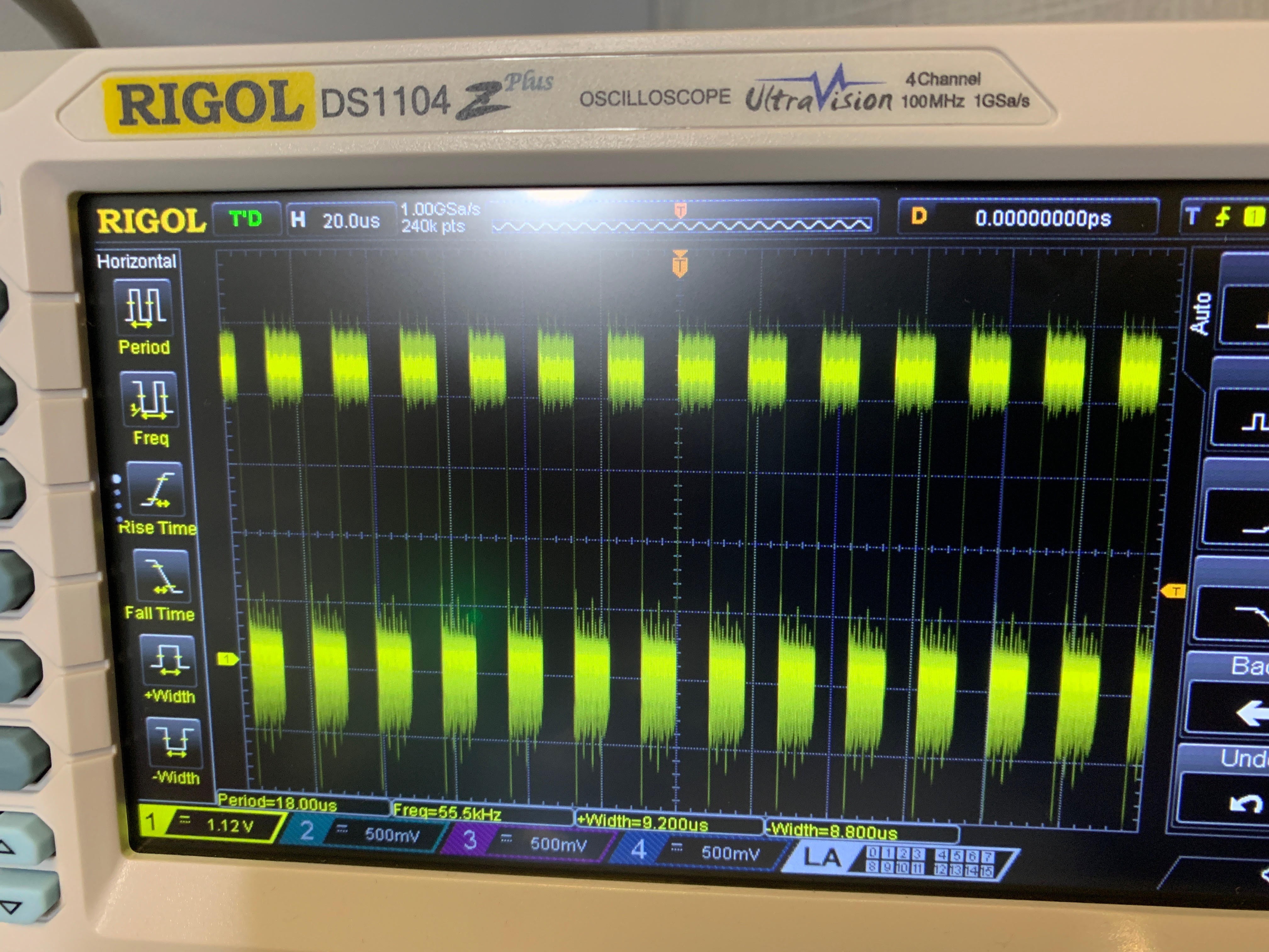
The most significant bit is ticking away at a cool 55.5 kHz, which I captured on the oscilloscope.
DIGIKEY DAY!
Is there anything better than getting a package from Digikey? Tomorrow I should receive a bunch of basic 74HC gates (NAND, AND, OR, XOR) which I'll use when working on the ALU. So, it's tempting to shift right away over onto that part of the project.
However, I also need to build a second 8-bit counter to act as the subroutine counter register and it will have the same design as the module above. That'll just be busy work, since I know the program counter works, but it needs to get done.
Another work item for the near term is to go ahead and produce a few other utility registers, like the index register, that the machine will use and which don't involve much complexity. I figure the more of the simple modules I have finished and on hand, the more I have to work with when I begin to piece together the control and memory logic.
I also need to figure out what I want to call this computer project.
Discussions
Become a Hackaday.io Member
Create an account to leave a comment. Already have an account? Log In.