 adria.junyent-ferre
The Joystick board is pretty simple, it contains 4 LEDs, 3 push buttons and a 2 axis joystick that we got from a Parallax board (https://uk.rs-online.com/web/p/products/7813064/)

The board has two connectors where two (repurposed) ethernet cables are wired. In a future design I would rather remove the LEDs and reduce the number of switches to use a single ethernet cable or perhaps a simple three wire cable but at the moment I didn't want to do any major redesign of the circuits.
The PCB was designed to be 2-layer and milled using our Bantam Tools Desktop CNC. This has some implications: I avoid connecting to through-hole legs from both sides of the board and make bias be far from components to simplify soldering. Still, these circuits are pretty simple and the board was very easy to route.
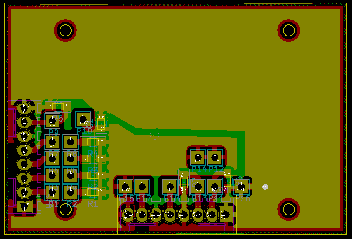
The motor controller board takes a DC voltage straight from the battery to feed an Arduino board that reads the inputs from the joystick board and sends a PWM signal plus a direction signal to two DC motor drivers. The board also has a socket where we connect an Adafruit nrf8001 BLE module (https://www.adafruit.com/product/1697). This module is optional and I'm very skeptical about the interest to enable bluetooth control in a real wheelchair because of the safety implications but it was good fun to be able to radio-control the wheelchair for testing purposes.
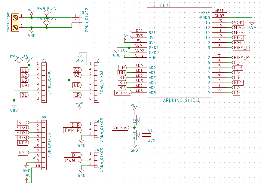
The motor controller board can also measure the voltage of the battery. At present there's no BMS for the battery and no software in place to cut off the power when the battery runs low but this is available for future use.
Once again, the PCB was designed for milling:
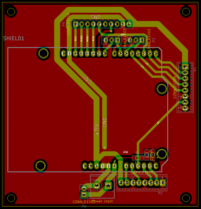
I'm not expert designing PCB layouts but I did my best to keep loops to a minimum and use decent trace widths. None of this is really high frequency, therefore I hope the board does the trick fairly well. I also relied on the decoupling capacitors of the Arduino and the bluetooth board but there's plenty of room to add other stuff in future iterations of this design.
A few other pictures:
As you can see, I had chosen a small case for the joystick and in the end I struggled to fit everything inside. I also had to remove a connector to be able to close the box. Ugly as it looks, in fact things weren't under heavy compression and it is perfectly ok to open and close the box any time:

The controller board sits on top of the battery in the back. It is relatively lightweight and I couldn't find a better way to hold it. This prototype is only for indoor use, the motors, the battery and all enclosures have relatively low IP rating. It is good enough to withstand dust and light vibration from normal use indoors but I wouldn't expose it to rain or any outdoors conditions.

A neat thing about the design is that if we remove the bluetooth board, we leave a big socket in place with access to the SPI pins of the microcontroller that can be used to connect other hardware for future expansion as well.
Discussions
Become a Hackaday.io Member
Create an account to leave a comment. Already have an account? Log In.