Close
0%
0%

Beat707

A MIDI sequencer

Similar projects worth following
This project uses the Arduino environment for implementing a MIDI sequencer, with additional external FRAM to store the data.

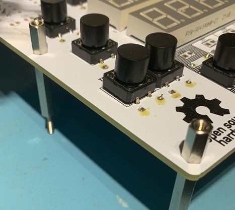
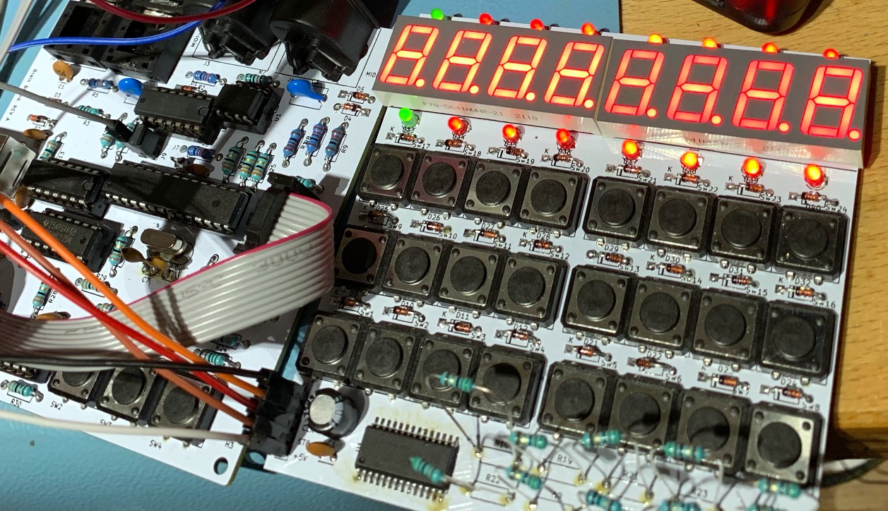
In 2017 William Kalfelz started with some cheap 7-segment / button boards from eBay and an ATMega to implement a MIDI sequencer. See this video:

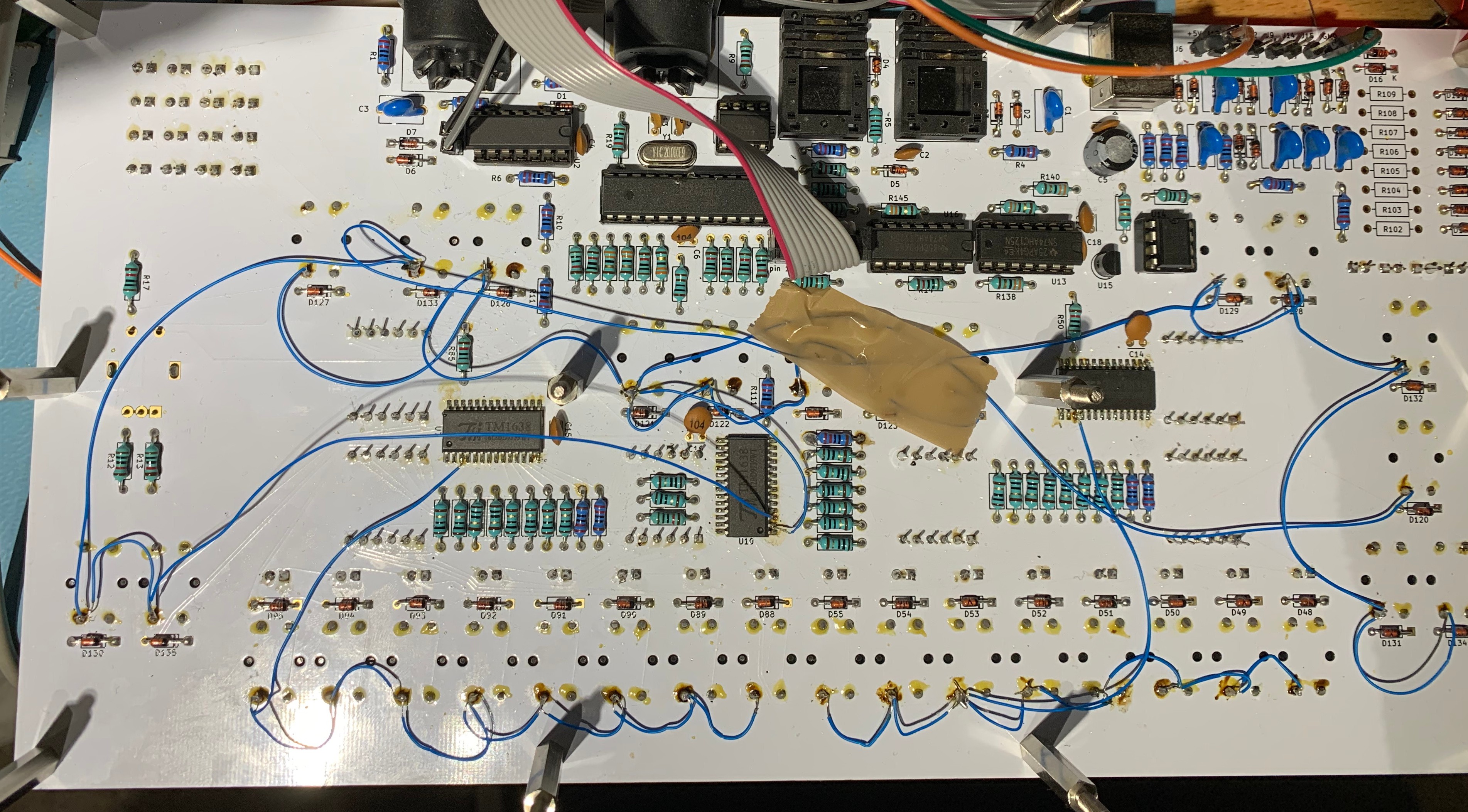
Later Gert Borovčak built a version as well and helped improving the firmware with William. He even manually desoldered the 7-segment elements and buttons of the eBay board and soldered a custom version on perf board, see this video of a short demo performance:

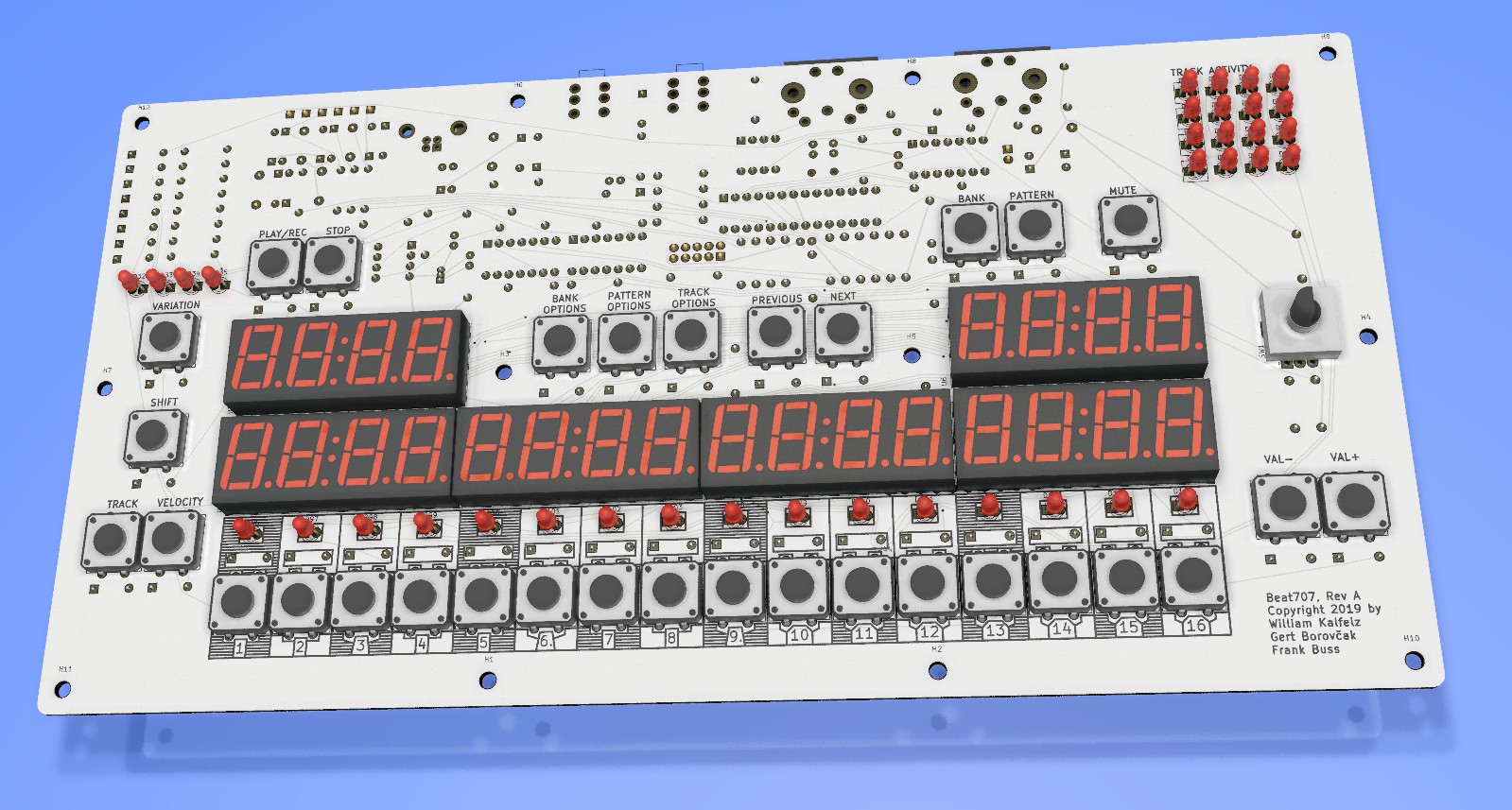
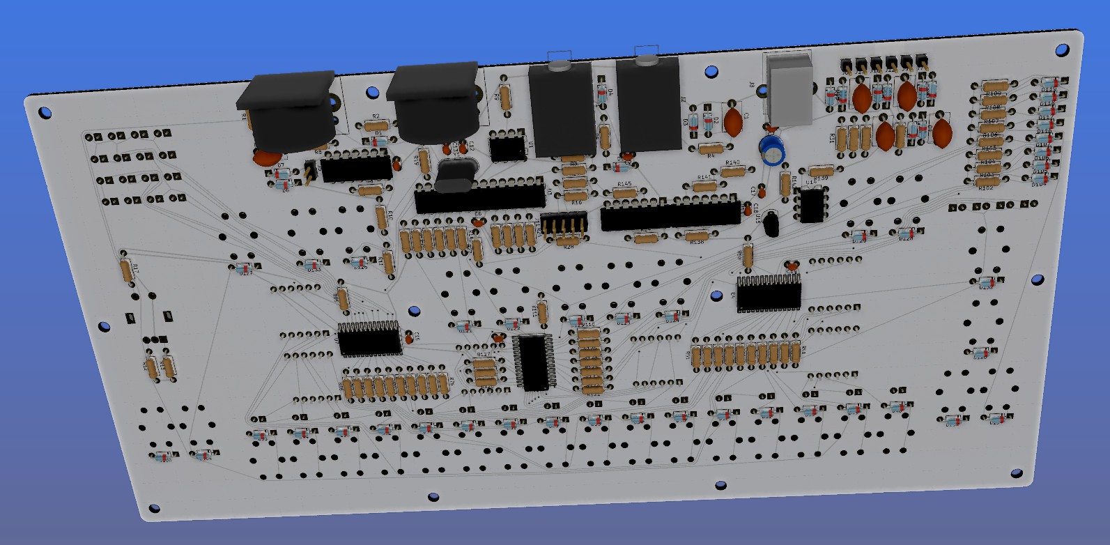
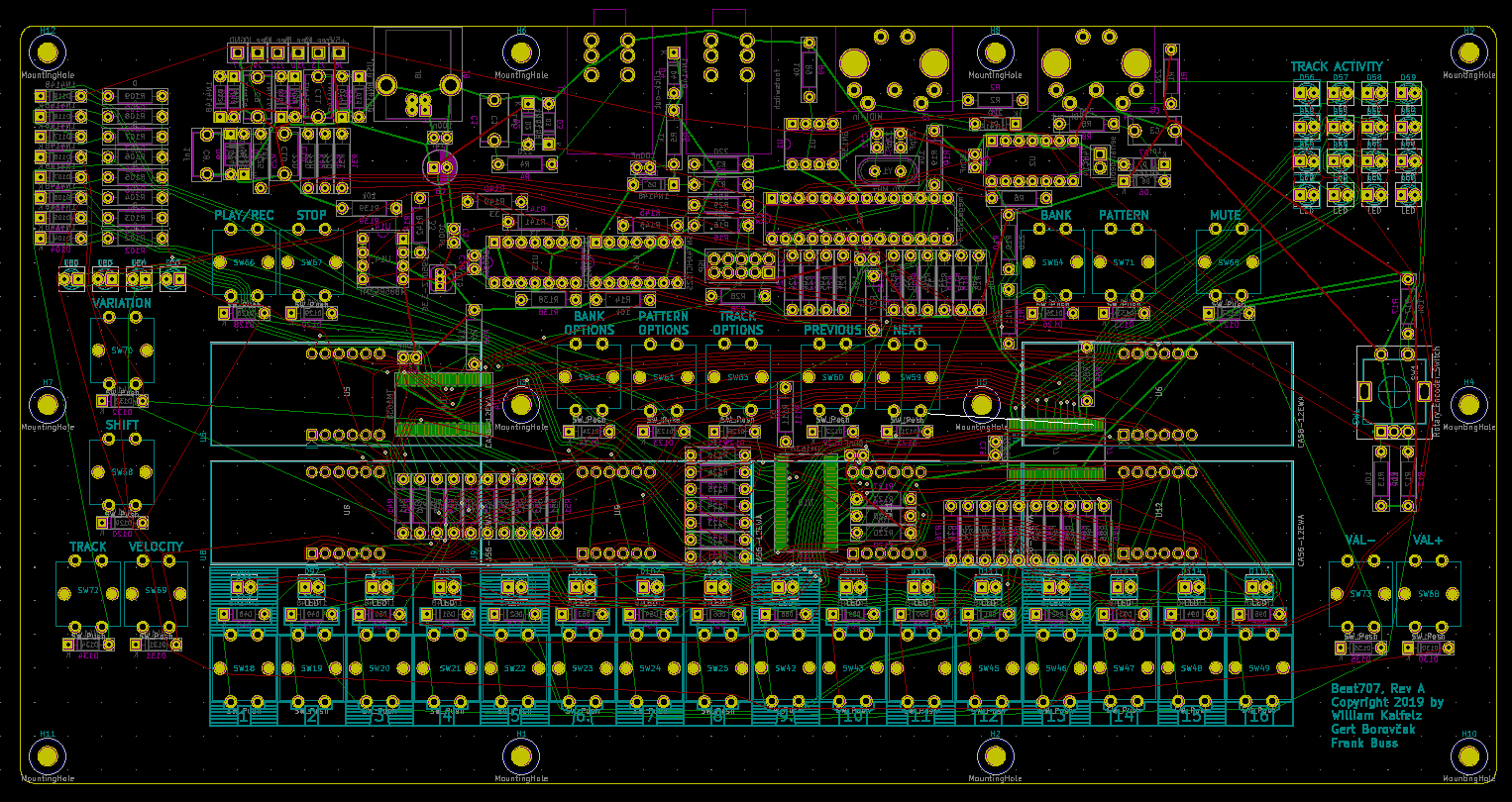
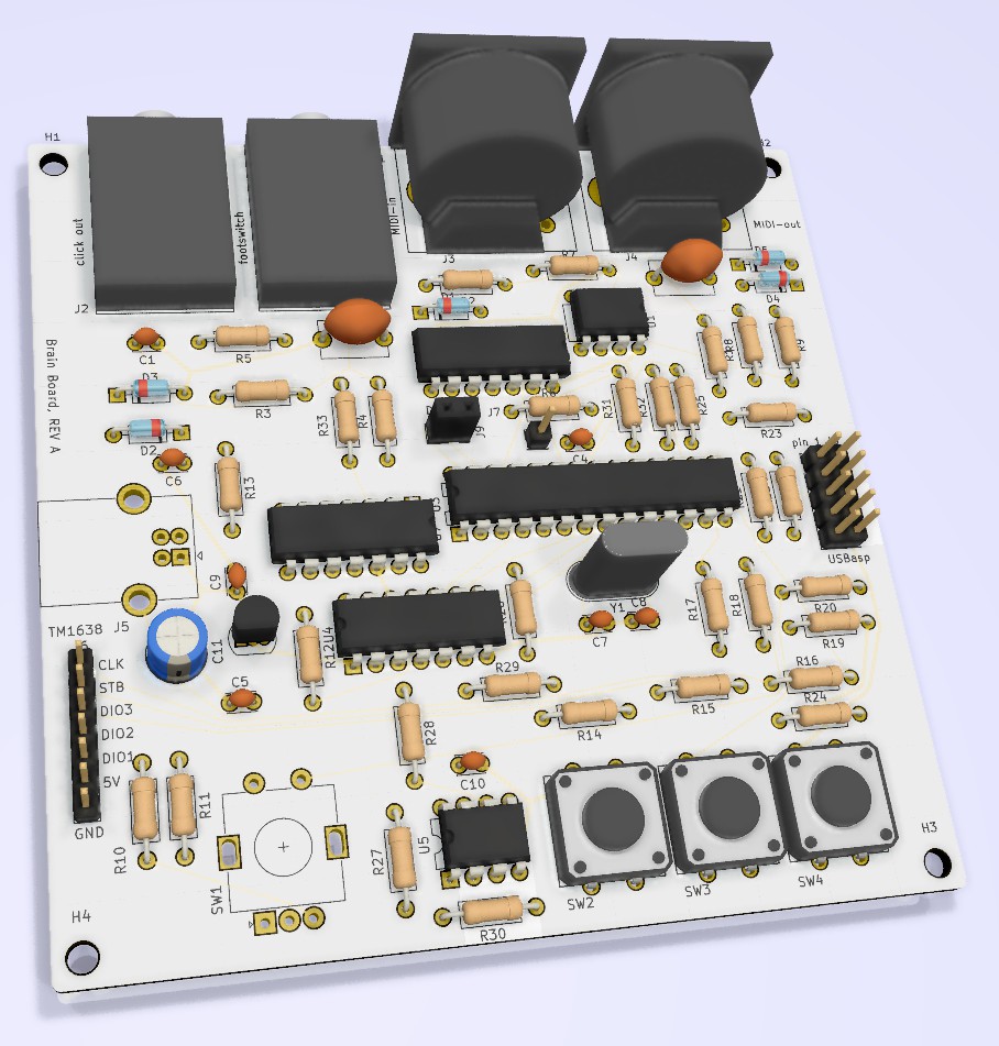
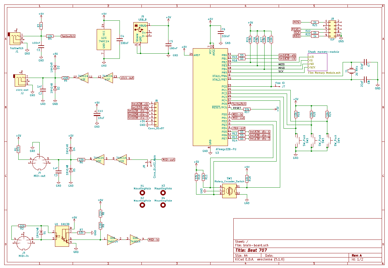
Then Gert asked Frank Buss to develop a professional PCB for it, maybe even to sell it later commercially. But everything will remain open source and open source hardware.

  • first hardware test

    Frank Buss02/28/2021 at 05:39 0 comments

    Everything is soldered and I'm testing now the hardware before porting William's code to the new FRAM etc. There was a problem with KiCad, I didn't do a DRC, and so all keys were connected only to one pin. But I could fix it with some blue wires:

    It works now. Here is a test with demonstrating the 8 possible brightness levels of the TM1638, which so far is not used in the current firmware:

  • new panel

    Frank Buss02/27/2021 at 18:11 0 comments

    Gert created a new design for the panel and I bought it from snijlab (cheaper than Ponoko, because shipping is within Europe)

    The line engravings (for example around the 1-16 keys and LEDs) and area engravings (most of the text) are difficult to see. Maybe better to print it, for example with the panel service from Beta Layout.

  • The big board arrived and panel test

    Frank Buss08/26/2019 at 17:51 0 comments

    The big board arrived. Frank soldered all components on the back side and placed all components on the front side:

    The buttons are original Omron B3F buttons. They cost more than the cheap no-name clones, but quality is better. They last longer and the contacts are not dirty, as they are sometimes with the clones. For this model you can buy different caps. With this cap, it looks like this:

    There are spacers to mount it on a base board in the enclosure, and to mount a panel on top:

    For the labeling Frank tried to engrave the red front panel and then sprayed acrylic color to it, wiping off the rest with isopropyl alcohol (you need this to avoid etching the acrylic red panel). Could be better, but good for a start:

    After some struggling with FreeCAD to export a file for the Nomad 883 CNC machine (e.g. it outputs a command to use inches, but then outputs millimeter coordinates), milling a small part the panel for testing was successful. Frank tried different spacer heights, and the 8 mm version, in combination with sanding off the 4 edges of the 7-segment display, was perfect:

    There are some minor details to improve, e.g. for the screws there needs to be milled some countersinks for a flat surface, and the engraving for the text needs to be smaller (all milled with the same 1.6 mm drill bit, should be changed to 0.8 mm for the engraving). But now the LEDs can be soldered, because the right lead offset is known, and then the board can be tested.

    Meanwhile Gert started to write a user manual. Shouldn't take long now to finish the first fully working prototype.

  • Planning an enclosure for it

    Frank Buss08/07/2019 at 18:04 0 comments

    Frank designed a first concept of an enclosure for the synth with FreeCAD:

    The red transparent front is planned to be an acrylic panel, which allows to see the red 7 segment display, but dims the rest, which should give it a professional look. The PCB is mounted directly under the panel in the second slot, mounted with standoffs. Below the PCB is enough room for all the connectors.

    The sides and bottom will be wood. Frank bought a walnut board from eBay:

    It is 25 mm thick. This would be very massive for the sides, so with a band saw it was cut in half:

    The result looks promising:

    Leveling it (the band saw is a cheap model and not very accurate) and cutting it to exact measurements will be done later with a CNC machine.

  • test boards arrived

    Frank Buss08/05/2019 at 15:01 3 comments

    The test boards arrived and Frank soldered it. Besides a small bug with a missing trace for the USB power supply (GND was not connected to the circuit GND) it worked. Test setup:

    Flashing the ATMega was a bit tricky as well. Maybe because of the 1k series resistors to use the programming pins for the programmer and for the SPI FRAM in parallel without jumpers, it didn't work at the default speed. But by editing the file /home/username/bin/arduino-1.8.9/hardware/arduino/avr/programmers.txt and adding the "-B 10" command line option to the usbasp programming line, the programming speed was reduced and it worked. And another trick: if it is a fresh ATMega, you have to program the fuses the right way. This can be done with avrdude, the details are on the Github page.

    For testing, there is a debug output jumper. If closed, it controls the MIDI output, but if open, it can be connected to a serial port receiver and you can see debug messages in the Arduino serial port monitor.

    The planned LEDs were a bit dim as well, but was fine with brighter ones and the 7-segment LEDs and LED brightness could be matched with the right resistors. A full test of all hardware components is in the Github repository. Now the big board is in production.

  • designing the big board

    Frank Buss08/01/2019 at 23:01 0 comments

    While waiting for the test boards, Frank created the big board and Gert placed the components and added some silk screen labels. Collaboration was easy with github and Slack. KiCad rendering of the top side:

    The idea is to use standoffs and mount the MIDI connectors etc. on the back side of the PCB. Then on the top side an acrylic panel could be mounted. This is how the bottom side looks like:

    The only SMD parts are the 3 TM1638 chips. If we sell it as a DIY kit, this would be pre-soldered, because many hobbyists still think SMD parts are difficult to solder.

    The routing was done with TopoR as well:

  • brain board and TM1638 test board

    Frank Buss07/30/2019 at 10:44 0 comments

    When building such a big board it is better to build simple, and possibly resuable, modules first, because small 10 cm x 10 cm boards are much cheaper than one big 30 cm x 15 cm board. And bugfixing and patching is easier as well.

    This is why Frank decided to build 2 modules: a brain board, which included the ATMega, the MIDI interface, and the FRAM storage IC. Here are the KiCad rendering of this board:

    This is the circuit diagram, also available in the github repository:

    A nice feature in KiCad is to create hierarchical sheets. You can see this at the top right in the circuit diagram for the memory module. Because the MB85RS2MT FRAM memory runs on 3.3 V and the rest of the circuit on 5 V, it needs some level translators and a 3.3 V voltage regulator. Instead of drawing this in the main circuit diagram, Frank created a sub-circuit diagram for it and included it with the hierarchical sheet feature. You can double clip on the symbol and the sub-circuit opens:

    One goal was to use all through hole parts if possible, so Frank did some tests to chose some good old ICs, which are fast enough for the SPI RAM, which can run up to the maximum ATMega SPI clock of 10 MHz. If you don't mind SMD parts, something like a 74LVC1T45 would be better, but according to the datasheet, and the measurements, the old TTL logic ICs work fine.

    For the user interface and the 7-segment display, Frank designed a TM1638 test board. This chip can sample more keys and control more LEDs, than the usual eBay TM1638 board has, so he created a board which was fully populated, to test the full functionality:

    Routing was done with TopoR, a very powerful router which minimized vias and trace length, and it can create old-school like curvy traces:

    An additional improvement over the eBay board are the low value series resistors, to balance the brightness of the LEDs and 7-segment display, This is the circuit diagram:

    There is an optional resistor for each key. This can be used to encode a version number in binary by populating or leaving out resistors.

    A nice feature of KiCad is if you use the # in front of the name, then the part will be excluded from the netlist. For the big main board, 3 instanced of this TM1638 board will be instantiated as sub-circuits. But in each sub-circuit you can individually name the components. This means there could be 2 instances all with keys, and the 3rd instance with 8 resistors to encode a PCB version. A firmware then could query the version, and work dynamically according to it, so that you need only one firmware version, even if you change the board later, but want to support existing users of old boards with new firmware features.

    You can also see the additional series resistors to adjust the brightness. Compare this to the eBay board, which has no resistors, which is also bad, because the max current can get higher than the max impulse current of the LED allows, and the TM1638 can get unnecessary hot.

View all 7 project logs

Enjoy this project?

Share

Discussions

Similar Projects

Does this project spark your interest?

Become a member to follow this project and never miss any updates