 Frank Buss
When building such a big board it is better to build simple, and possibly resuable, modules first, because small 10 cm x 10 cm boards are much cheaper than one big 30 cm x 15 cm board. And bugfixing and patching is easier as well.
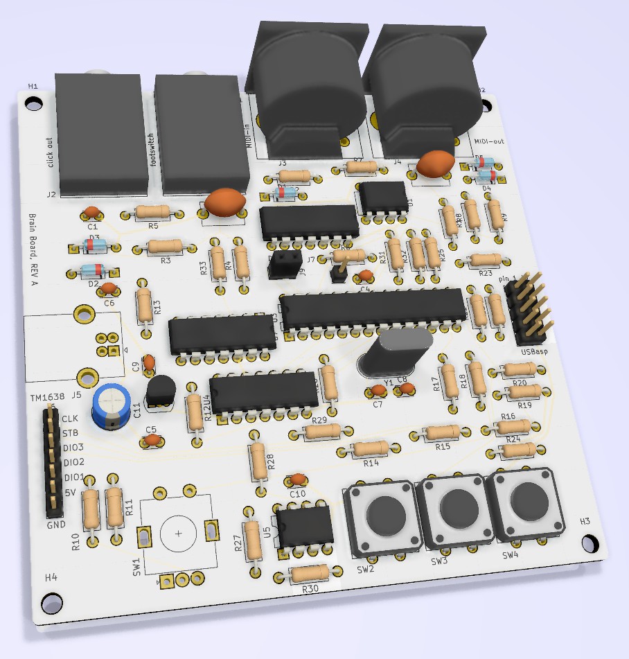
This is why Frank decided to build 2 modules: a brain board, which included the ATMega, the MIDI interface, and the FRAM storage IC. Here are the KiCad rendering of this board:
This is the circuit diagram, also available in the github repository:
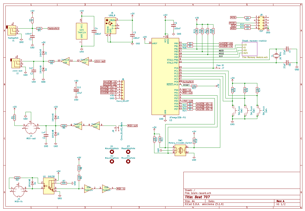
A nice feature in KiCad is to create hierarchical sheets. You can see this at the top right in the circuit diagram for the memory module. Because the MB85RS2MT FRAM memory runs on 3.3 V and the rest of the circuit on 5 V, it needs some level translators and a 3.3 V voltage regulator. Instead of drawing this in the main circuit diagram, Frank created a sub-circuit diagram for it and included it with the hierarchical sheet feature. You can double clip on the symbol and the sub-circuit opens:
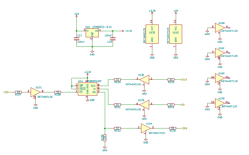
One goal was to use all through hole parts if possible, so Frank did some tests to chose some good old ICs, which are fast enough for the SPI RAM, which can run up to the maximum ATMega SPI clock of 10 MHz. If you don't mind SMD parts, something like a 74LVC1T45 would be better, but according to the datasheet, and the measurements, the old TTL logic ICs work fine.
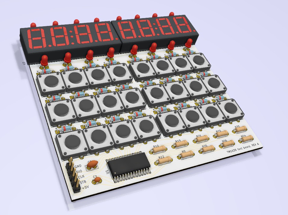
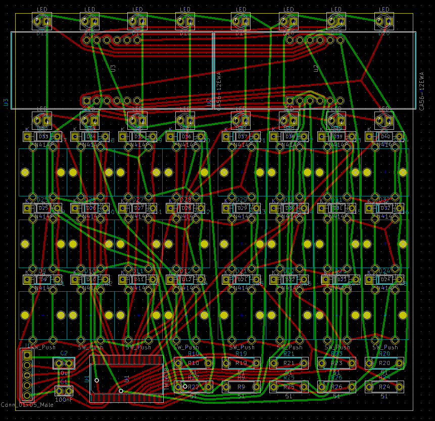
For the user interface and the 7-segment display, Frank designed a TM1638 test board. This chip can sample more keys and control more LEDs, than the usual eBay TM1638 board has, so he created a board which was fully populated, to test the full functionality:
Routing was done with TopoR, a very powerful router which minimized vias and trace length, and it can create old-school like curvy traces:
An additional improvement over the eBay board are the low value series resistors, to balance the brightness of the LEDs and 7-segment display, This is the circuit diagram:
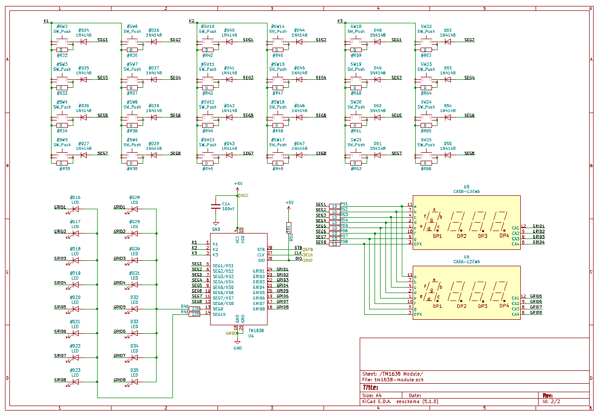
There is an optional resistor for each key. This can be used to encode a version number in binary by populating or leaving out resistors.
A nice feature of KiCad is if you use the # in front of the name, then the part will be excluded from the netlist. For the big main board, 3 instanced of this TM1638 board will be instantiated as sub-circuits. But in each sub-circuit you can individually name the components. This means there could be 2 instances all with keys, and the 3rd instance with 8 resistors to encode a PCB version. A firmware then could query the version, and work dynamically according to it, so that you need only one firmware version, even if you change the board later, but want to support existing users of old boards with new firmware features.
You can also see the additional series resistors to adjust the brightness. Compare this to the eBay board, which has no resistors, which is also bad, because the max current can get higher than the max impulse current of the LED allows, and the TM1638 can get unnecessary hot.
Discussions
Become a Hackaday.io Member
Create an account to leave a comment. Already have an account? Log In.